A Fast Stochastic Contact Model for Planar Pushing and Grasping: Theory and Experimental Validation
Abstract
Based on the convex force-motion polynomial model for quasi-static sliding, we derive the kinematic contact model to determine the contact modes and instantaneous object motion on a supporting surface given a position controlled manipulator. The inherently stochastic object-to-surface friction distribution is modelled by sampling physically consistent parameters from appropriate distributions, with only one parameter to control the amount of noise. Thanks to the high fidelity and smoothness of convex polynomial models, the mechanics of patch contact is captured while being computationally efficient without mode selection at support points. The motion equations for both single and multiple frictional contacts are given. Simulation based on the model is validated with robotic pushing and grasping experiments. 111Our open-source simulation software and data are available at: https://github.com/robinzhoucmu/Pushing
I Introduction
Uncertainty from robot perception and motion inaccuracy is ubiquitous. Planning and control without explicit reasoning about uncertainty can lead to undesirable results. For example, grasp planning [17, 5] is often prone to uncertainy: the object moves while the fingers close and ends up in a final relative pose that differs from planned. Consider the process of closing a parallel jaw gripper shown in Fig. 1, the object will slide when the first finger engages contact and pushes the object before the other one touches the object. If the object does not end up slipping out, it can be jammed at an undesired position or grasped at an unexpected position. A high fidelity and easily identifiable model with minimum adjustable parameters capturing all these possible outcomes would enable synthesis of robust manipulation strategy.
Although we can reduce uncertainty by carefully controlling the robot’s environment, as in most factory automation scenarios, such approach is both expensive and inflexible. Effective robotic manipulation requires an understanding of the underlying physical processes. Mason [15] explored using pushing as a sensorless mechanical funnel to reduce uncertainty. Whitney [23] analyzed the mechanics of wedging and jamming during peg-in-hole insertion and designed the Remote Center Compliance device that significantly increases the success of the operation under motion uncertainty. With a well defined generalized damper model, Lozano-Perez et al. [9] and Erdmann [4] developed strategies to chain a sequence of operations, each with a certain funnel, to guarantee operation success despite uncertainty. These successes stem from robustness analysis using simple physics models.
A large class of manipulation problems involve finite planar sliding motion. In this paper, we propose a quasi-static kinematic contact model for such a class. We model the inherent stochasticity in frictional sliding by sampling the physics parameters from proper distributions. We validate the model by comparing simulation with large scale experimental data on robotic pushing and grasping tasks. The model serves as good basis for both open loop planning and feedback control.
The proposed contact model is a direct extension of [27], which presents a dual mapping between an applied wrench and a resultant object twist. In this paper, we map a given position controlled input (which is common in most standard industrial manipulators) to the resultant twist including the no-motion case for jamming and grasping. The applied wrench is solved as an intermediate output without needing to control it. The rest of the paper is organized as follows:
-
•
Section II describes the previous work.
- •
- •
-
•
Section V develops sampling strategies of physically consistent model parameters that captures the inherent frictional stochasticity.
-
•
Section VI demonstrates experimental evaluation of both pushing and grasping simulation using the proposed contact model.
We assume quasi-static rigid body planar mechanics [14] where inertia forces and out-of-plane moments are negligible.
II Related Work
The mechanics of pushing and grasping involving finite object motion with frictional support was first studied in [15]. A notable result is the voting theorem which dictates the sense of rotation given a push action and the center of pressure regardless of the uncertain pressure distribution. Brost [1] used this result to construct the operational space for planning squeezing and push-grasping actions under uncertainty. However, many unrealistic assumptions are made in order to reduce the state space and create finite discrete transitions, including infinitely long fingers approaching the object from infinitely far away. Additionally, how far to push the object in the push-grasp action is not addressed. Peshkin and Sanderson [19] provided an analysis on the slowest speed of rotation given a single point push. They [20] used this result to design fences for parts feeding. Lynch and Mason [11] derived conditions for stable edge pushing such that the object will remain attached to the pusher without slipping or breaking contact. All of these results do not assume knowledge of the pressure distribution except the location of center of pressure. They can be classified as worse case guarantees without looking into the details of sliding motion. Despite being agnostic to pressure distribution, these methods tend to be overly conservative.
Another line of research is to identify the necessary physical parameters. Common approaches [10, 25] discretize the contact patch into grids and optimize for approximate criteria of force balancing. These methods naturally suffer from the downside of coarse discrete approximation of distributions or curse of dimensionality if fine discretization is adopted. Additionally, the instantaneous center of rotation of the object can coincide with one of the support points, rendering the kinematic solution computationally hard due to combinatorial sliding/sticking mode assignment for each support point.
Goyal et al. [7] noted that all the possible static and sliding frictional wrenches, regardless of the pressure distribution, form a convex set whose boundary is called as limit surface. The limit surface can be constructed from Minkowsky sum of frictional limit curves at individual support points without a convenient explicit form. Howe and Cutkosky [8] presented an experimental method to identify an ellipsoidal approximation given known pressure. Dogar and Srinivasa [3] used the ellipsoidal approximation and integrated with motion planners to plan push-grasp actions for dexterous hands. Closely related to our work, Lynch et al. [12] derived the kinematics of single point pushing with centered and axis aligned ellipsoid approximation. Zhou et al. [27] proposed a framework of representing planar sliding force-motion models using homogeneous even-degree sos-convex polynomials, which can be identified by solving a semi-definite programming. The set of applied friction wrenches is the 1-sublevel set of a convex polynomial whose gradient directions correspond to incurred sliding body twist. In this paper, we extend the convex polynomial model to associate a commanded rigid position-controlled end effector motion to the instantaneous resultant object motion. We show that single contact with convex quadratic limit surface model has a unique analytical linear solution which extends [12]. The case for a high order convex polynomial model is reduced to solving a sequence of such subproblems. For multiple contacts (e.g., pushing with multiple points or grasping) we need to add linear complementarity constraints [22] at the pusher points, and the entire problem is a standard linear complementarity problem (LCP).
III Notations and Background
We first introduce the following notations:
-
•
: the object center of mass used as the origin of the body frame. We assume vector quantities are with respect to body frame unless specially noted.
-
•
: the region between the object and the supporting surface.
-
•
: the friction force distribution function that maps a point in the contact area to its friction force the object applies on the supporting surface. For isotropic point Coulomb friction law, when the velocity at is nonzero, is in the same direction of the velocity. Its magnitude equals the pressure force multiplied by the coefficient of friction between the object and the supporting surface. When the object is static, is indeterminate and dependent on the externally applied force by the manipulator.
-
•
: the body twist (generalized velocity).
-
•
: the applied body wrench by the manipulator that quasi-statically balances the friction wrench from the surface.
-
•
: each contact point between the manipulator end effector and object in the body frame.
-
•
: applied velocities by the manipulator end effector at each contact point in the body frame.
-
•
: the inward normal at contact point on the object.
-
•
: coefficient of friction between the object and the manipulator end effector.
III-A Force-Motion Model
In this section we review the basics of force-motion models for planar sliding and the mechanics of pushing. We refer the readers to [6, 15, 27] for more details. Given a body twist , the components of the friction wrench are given by integrations over :
| (1) |
We can compute for each and form the set of all possible friction wrenches. Goyal et al. [6] defined the set boundary as limit surface. It is shown that the friction wrench set is convex and points on the limit surface correspond to friction wrenches when the object slides. Additionally, the normal for a point (wrench) on the limit surface is parallel to the corresponding twist. Zhou et al [27] showed that level sets of homogeneous even degree convex polynomials can approximate the limit surface geometry sufficiently well. Denote by the convex polynomial function, the twist for a given friction wrench is parallel to the gradient :
| (2) |
Additionally the inverse mapping can be efficiently computed. Given the twist , optimizing a least-squares objective with the Gauss-Newton algorithm gives the unique solution that corresponds to the wrench .
With a position-controlled manipulator, we are given contact points with inward normals , pushing velocities and coefficient of friction between the pusher and the object. The task is to resolve the incurred body twist and consistent contact modes (sticking, slipping, breaking contact) to maintain wrench balance.
IV Contact Modelling
IV-A Single point pusher
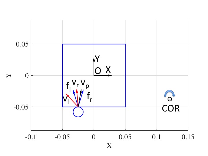
Let the COM be the point of origin of the local body frame a level set representation of limit surface . We introduce the concept of motion cone first proposed in [15]. Let , and denote by and the left and right edges of the applied wrench cone with corresponding resultant twist directions and respectively. The left edge of the motion cone is and the right edge of the motion cone is . If the contact point pushing velocity is inside the motion cone, i.e., , the contact sticks. When is outside the motion cone, sliding occurs. If is to the left of , then the pusher slides left with respect to the object. Otherwise if is to the right of , then the pusher slides right as shown in Fig. 2(a).
The following constraints hold assuming sticking contact:
| (3) | ||||
| (4) | ||||
| (5) | ||||
| (6) |
In the case of ellipsoidal (convex quadratic) representation, i.e., where is a positive definite matrix, the problem is a full rank linear system with a unique solution. Lynch et al. [12] gives an analytical solution when is diagonal. We show that a unique analytical solution exists for any positive definite symmetric matrix . Let , and , equations 3-6 can then be combined as one linear equation:
| (7) |
Theorem 1
Pushing with single sticking contact and the convex quadratic representation of limit surface (abbreviated as ) has a unique solution from a linear system.
Proof:
It is obvious that we only need to prove is invertible. 1) The row vectors of are linearly independent and span a plane. 2) implies is orthogonal to the spanned plane. 3) If is not full rank, then must lie in the spanned plane and is therefore orthogonal to . This contradicts with the fact that for positive definite matrix and nonzero vector . ∎
Corollary 1
Pushing with single sticking contact and the general convex polynomial limit surface representation is reducible to solving a sequence of sub-problems .
For general convex polynomial representation , the following optimization is equivalent to equation 3-6:
| (8) | ||||
| subject to | (9) |
When is of convex quadratic (ellipsoidal) form, the analytical minimizer is . In the case of high order convex homogeneous polynomials, we can resort to an iterative solution where we use the Hessian matrix as a local ellipsoidal approximation, i.e., set and compute until convergence.
When is outside of the motion cone, assuming right sliding occurs without loss of generality, the wrench applied by the finger equals . The resultant object twist follows the same direction as with proper magnitude such that the contact is maintained:
| (10) | |||
| (11) |
IV-B Multi-contacts
Mode enumeration is tedious for multiple contacts. The linear complementarity formulation for frictional contacts ([22]) provides a convenient representation. Denote by the total number of contacts, the quasi-static force-motion equation is given by:
| (12) |
where the total applied wrench is the sum of normal and frictional wrenches over all applied contacts:
| (13) |
is the normal force magnitude along the normal , and is the vector of tangential friction force magnitudes along the column vector basis of . The velocity at contact point on the object is given by . The first order complementarity constraints on the normal force magnitude and the relative velocity are given by:
| (14) |
The complementarity constraints for Coulomb friction are given by:
| (15) | ||||
| (16) |
where is the coefficient of friction at and . In the case of ellipsoid (convex quadratic) representation, i.e., where is a positive definite matrix, equations 12 to 16 can be written in matrix form:
| (17) | ||||
where the binary matrix equals , , the stacking matrix equals , the stacking matrix equals , the stacking vector equals and vector equals .
Note that the positive scalar will not affect the solution value of since and will scale accordingly. Hence, we can drop the scalar and further substitute into equation 17 and reach the standard linear complementarity form as follows:
| (18) | ||||
Similarly, for the case of high order convex homogeneous polynomials, we can iterate between taking the linear Hessian approximation and solving the LCP problem in equation 18 until convergence.
Lemma 1
The object is quasi-statically jammed or grasped if the LCP problem (equation 18) yields no solution.
Fig. 3 provides a graphical proof. When equation 18 yields no solution, either there is no feasible kinematic motion of the object without penetration or all the friction loads associated with the feasible instantaneous twists cannot balance against any element from the set of possible applied wrenches. In this case, the object is quasi-statically jammed or grasped between the fingers. Neither the object nor the end effector can move.
V Stochasticity
Uncertainty is inherent in frictional interaction. Two major sources contribute to the uncertainty in planar motion: 1) indeterminancy of the supporting friction distribution due to changing pressure distribution and coefficients of friction between the object and support surface; 2) the coefficient of friction between the object and the robot end effector. We sample uniformly from a given range. To model the effect of changing support friction distribution, for a even degree- strictly convex polynomial (except at the point of origin) with monomial terms [27], we sample the polynomial coefficient parameters in from a distribution that satisfies:
-
1.
Samples from the distribution should result in a even degree homogeneous convex polynomial to represent the limit surface.
-
2.
The mean can be set as a prior estimate and the amount of variance controlled by one parameter.
The Wishart distribution [24] with mean and variance is defined over symmetric positive semidefinite random matrices as a generalization of the chi-squared distribution to multi-dimensions. For ellipsoidal (convex quadratic) , we can directly sample from with mean and variance where is some estimated value from data or fitted for a particular pressure distribution. Sampling from general convex polynomials is hard. Fortunately, we find that sampling from the sos-convex [18, 13] polynomials subset is not. The key is the coefficient vector of a sos-convex polynomial has a unique one-to-one mapping to a positive definite matrix so that we can first sample from 222We have noted that adding a small constant on the diagonal elements of improves numerical stability. and then map back to . Given a sos-convex polynomial representation of , the Hessian matrix at is positive definite, i.e., for any non-zero vector , there exists a positive-definite matrix such that
| (19) |
In the case of fourth order polynomial we have . and are related through a set of linear equalities: equation (19) can be written as a set of sparse linear constraints on and .
| (20) |
where and are the constant sparse element indicator matrix and vector that only depend on the polynomial degree . Hence we can map each sampled back to . The degree of freedom parameter determines the sampling variance. The smaller is, the noisier the system will be.
VI Experimental Evaluation
VI-A Evaluation of Deterministic Pushing Model
We evaluate our deterministic model on the large scale MIT pushing dataset [26] and a smaller dataset [27] that has discrete pressure distributions. For the MIT pushing dataset, we use 10mm/s velocity data logs for 10 objects333Despite having the same experimental set up and similar geometry and friction property to the other two triangular shapes, the results for object Tr2 is about 1.5 -2 times worse. Due to time constraint, we have not ruled out the possibility that the data for object Tr2 is corrupted. on 3 hard surfaces including delrin, abs and plywood. The force torque signal is first filtered with a low pass filter and 5 wrench-twist pairs evenly spaced in time are extracted from each push action json log file. 10 random train-test splits (20 percent of the logs for training, 10 percent for validation and the rest for testing) are conducted for each object-surface scenario. On average, around 600 wrench-twist pairs are used for identification.
Given two poses and , we define the deviation metric which combines both the displacement and angular offset as , where is the characteristic length of the object (e.g., radius of gyration or radius of minimum circumscribed circle). A one dimensional coarse grid search over the coefficient of friction between the pusher and object is chosen to minimize average deviation of the predicted final pose and ground truth final pose on training data. Table I shows the average metric with a 95% percent confidence interval. Interestingly, we find that using more training data does not improve the performance much. This is likely due to the inherent stochasticity (variance) and changing surface conditions as reported in [26].
The objects in the MIT pushing dataset are closer to uniform pressure. We also evaluate on a smaller dataset [27] that has discrete pressure distributions, and in particular three points support whose pressure can be derived exactly as ground truth. We use 400 wrench twists sampled from the ideal limit surface for training. The coefficient of friction between the object and pusher is determined by a grid search over 40 percent of the logs to determine. We use the remaining 60 percent to evaluate simulation accuracy. Note that in both evaluations, the accuracy of deterministic models are upper bounded by the system variance.
| rect1 | rect2 | rect3 | tri1 | tri3 | ellip1 | ellip2 | ellip3 | hex | butter | |
| poly4-delrin | 8.280.29 | 5.370.23 | 6.100.21 | 9.710.33 | 7.540.23 | 7.680.51 | 8.901.40 | 7.350.38 | 6.380.28 | 4.830.27 |
| quad-delrin | 8.600.35 | 5.920.14 | 8.200.16 | 9.900.41 | 8.180.15 | 6.850.25 | 6.290.24 | 8.080.51 | 6.420.12 | 5.970.23 |
| delrin | 35.48 | 40.53 | 35.98 | 36.91 | 34.66 | 32.18 | 38.05 | 33.37 | 33.55 | 34.09 |
| poly4-abs | 5.860.11 | 7.480.80 | 3.590.12 | 7.130.26 | 5.170.38 | 8.451.13 | 9.181.26 | 5.930.19 | 7.560.39 | 3.940.11 |
| quad-abs | 6.070.16 | 6.740.27 | 6.190.18 | 8.000.37 | 7.170.37 | 6.660.28 | 7.690.27 | 5.780.21 | 8.190.21 | 5.390.15 |
| abs | 34.14 | 39.74 | 33.98 | 35.43 | 32.37 | 32.68 | 33.53 | 32.45 | 33.23 | 33.53 |
| poly4-plywood | 6.860.71 | 6.860.13 | 5.930.33 | 4.610.13 | 7.210.47 | 4.390.16 | 4.990.31 | 5.720.31 | 8.410.24 | 4.720.17 |
| quad-plywood | 6.200.20 | 7.220.18 | 6.880.18 | 5.960.19 | 9.430.56 | 4.420.12 | 5.840.20 | 6.460.26 | 8.85 0.17 | 6.050.22 |
| plywood | 31.86 | 33.22 | 32.94 | 32.81 | 33.78 | 27.24 | 28.23 | 33.29 | 32.77 | 34.10 |
| 3pts1 | 3pts2 | 3pts3 | 3pts4 | |
| poly4-hardboard | 3.520.21 | 2.750.25 | 2.920.27 | 2.800.23 |
| quad-hardboard | 3.820.24 | 3.630.27 | 3.350.23 | 3.960.28 |
| hardboard | 16.63 | 13.86 | 14.83 | 15.15 |
| poly4-plywood | 3.780.11 | 2.800.15 | 2.840.16 | 3.260.11 |
| quad-plywood | 4.240.15 | 3.560.17 | 3.280.08 | 4.120.13 |
| plywood | 16.56 | 13.81 | 15.27 | 14.20 |
VI-B Pushing with stochasticity
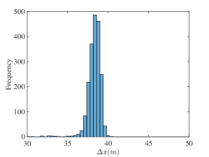
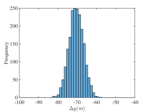
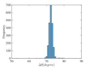
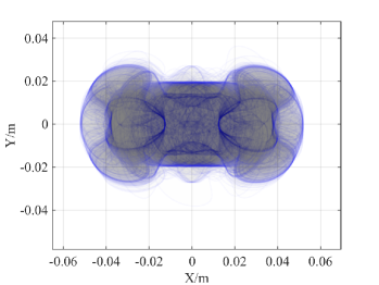
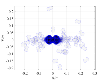
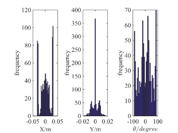
The experiment in [26] demonstrates that the same 2000 pushes in a highly controlled setting result in a distribution of final poses. We perform simulations using the same object and pusher geometry and push distance. The 2000 resultant trajectories and histogram plot of pose changes are shown in Fig. 4 and 5 respectively. We note that although the mean and variance pose changes are similar to the experiments with abs material in [26], the distribution resemble a single Gaussian distribution which differs from the multiple modes distribution in Figure 10 of [26]. We conjecture this is due to a time varying stochastic process where coefficients of friction between surfaces drift due to wear.
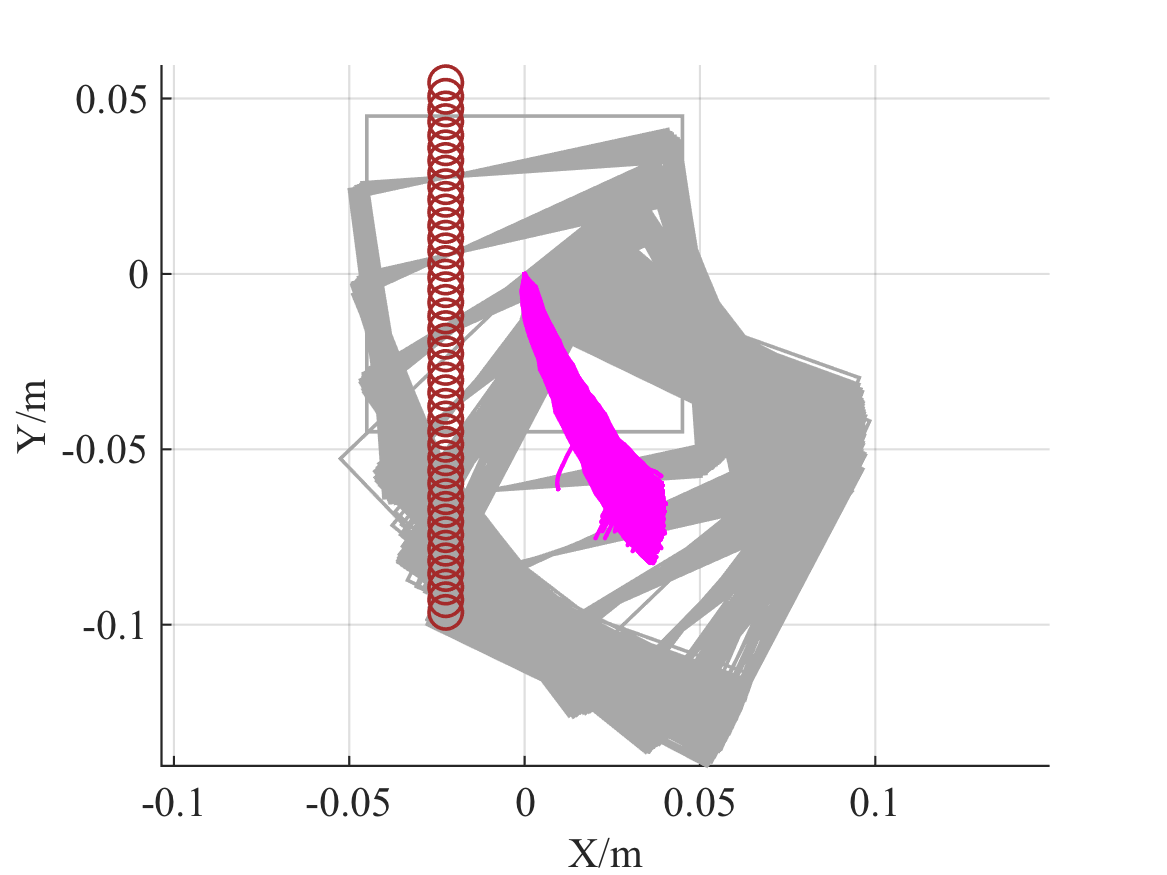
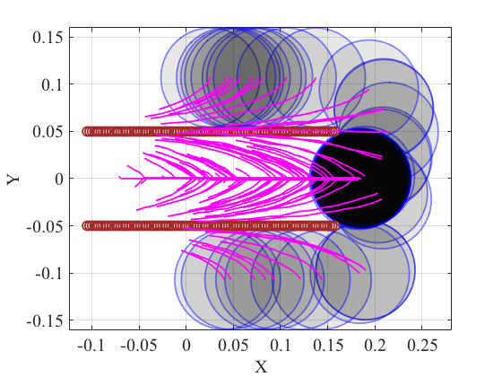
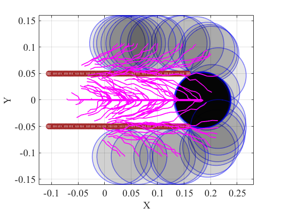
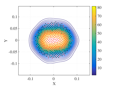
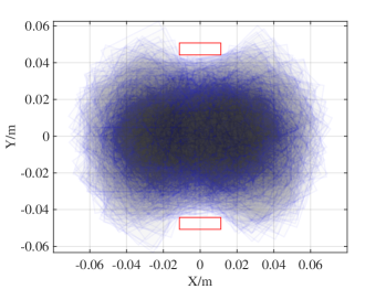
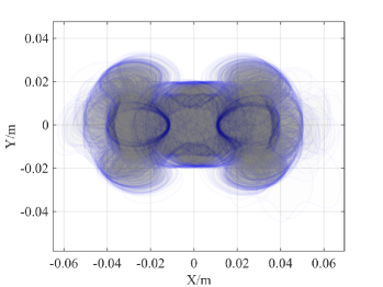
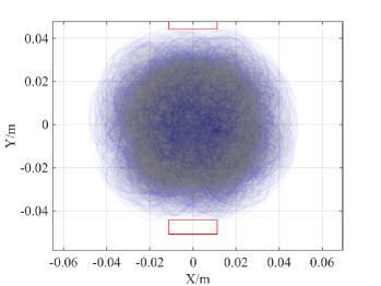
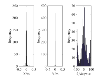
We also evaluate the effects of uncertainty reduction with 2 point fingers under the stochastic contact model. The circular object has radius of 5.25cm. The two fingers separated by 10cm perform a straight line push of 26.25cm. The desired goal is to have the object centered with respect to the two fingers. Fig. 6(a) and 6(b) compare the resultant trajectories under different amount of system noise. We find that despite larger noise in the resultant trajectories, the convergent region of the stable goal pose differs by less than 5% and the difference is mostly around the uncertainty boundary. A kernel density plot of the convergence region is shown in in Fig. 6(c) for . We conclude that multiple active constraints induce a large region of attraction.
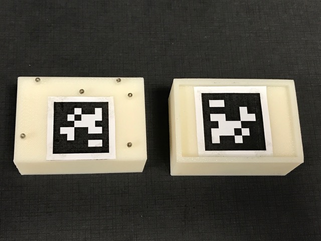
VI-C Grasping under uncertainty
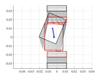
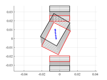
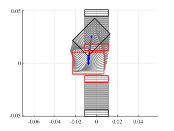
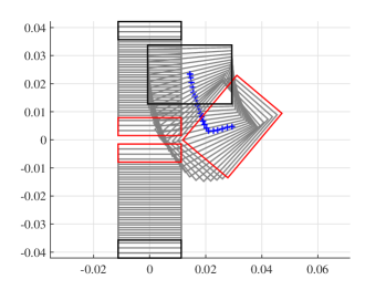
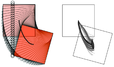
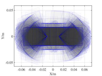
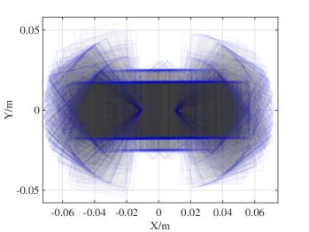
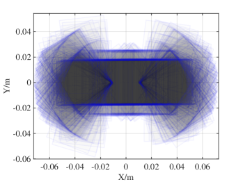
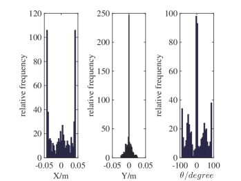
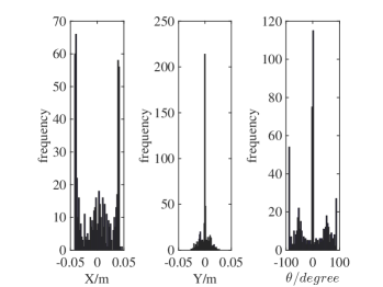
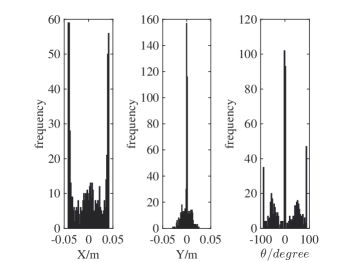
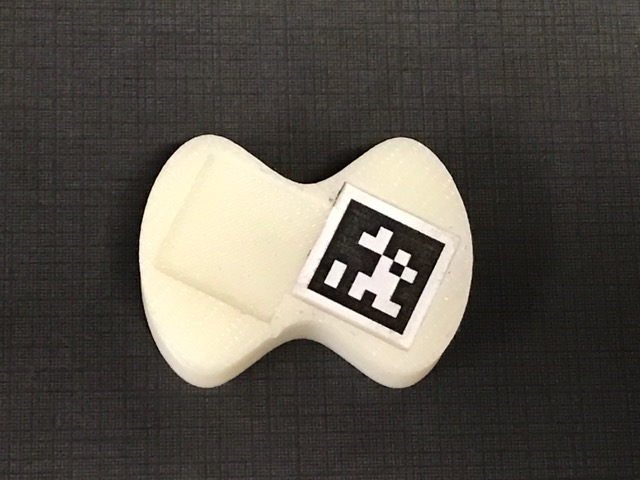
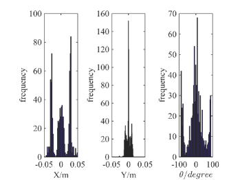
We conduct robotic experiments to evaluate our contact model for grasping. Fig. 7(a) shows two rectangular objects with the same geometry but different pressure distributions. Another experiment is conducted for a butterfly shaped object shown in Fig. 8(a). We use the Robotiq hand [21] and represent it as a planar parallel-jaw gripper with rectanglular fingers as shown in Fig. 7(b) and Fig. 8(b). Convex quadratic limit surface parameterizations are trained from wrench-twist pairs from a uniform friction distribution along the object boundary. The sampling degree of freedom equals 250 with contact friction coefficient sampled uniformly from [0.015, 0.02]. The simulated results with the stochastic contact model match well with the rectangles for both pressure distribution. However, the model fails to capture the stability of grasps and the deformation of objects. In the case of a butterfly-shaped object, many unstable grasps and jamming equilbria exist, but as the fingers increase the gripping force the object will “fly” away as the stored elastic energy turns into large accelerations which violates the quasistatic assumptions of our model, as revealed in the scattered post-grasp distribution in Fig. 8(e). We also compare the cases where dynamics do not play a major role: Fig. 8(g) shows the zoomed in plots to compare with simulation results in Fig. 8(c). We can see that the model simulation deviates more compared with the case for rectangular geometry. Comparing the histogram plot in Fig. 8(d) and Fig. 8(h), we can see that the simulation returns more jamming and grasping final states as illustrated by the spikes in .
VII Conclusions and Future Work
We extend the convex polynomial force-motion model in [27] which gives the dual mapping between friction wrench and twist to the kinematic level where the applied controls are velocity input (single and multiple) contacts. Additionally, we derive methods that enable sampling from the family of sos-convex polynomials to model the inherent uncertainty in frictional mechanics. The stochastic contact models are validated with large scale robotic pushing and grasping experiments. We also see the limitation of a first order quasistatic model in the butterfly shaped object grasping experiment. Much work remains to be done. On the simulator end: 1) how to increase the accuracy without losing convergence speed for high order polynomial based representation of and 2) how to handle penetration properly when the integration step is large. On the application side: 1) how to quickly identify both the mean and variance of the sampling distribution to match with experimental data and 2) how to plan a robust sequence of grasp and push actions for uncertainty reduction using the stochastic contact model.
Acknowledgments
The authors would like to thank Alberto Rodriguez and Kuan-Ting Yu for discussions and providing details of the MIT pushing dataset. This work was conducted in part through collaborative participation in the Robotics Consortium sponsored by the U.S Army Research Laboratory under the Collaborative Technology Alliance Program, Cooperative Agreement W911NF-10-2-0016 and National Science Foundation IIS-1409003. The views and conclusions contained in this document are those of the authors and should not be interpreted as representing the official policies, either expressed or implied, of the Army Research Laboratory of the U.S. Government. The U.S. Government is authorized to reproduce and distribute reprints for Government purposes notwithstanding any copyright notation herein.
References
- Brost [1988] Randy C Brost. Automatic grasp planning in the presence of uncertainty. The International Journal of Robotics Research, 7(1):3–17, 1988.
- Brost and Mason [1991] Randy C Brost and Matthew T Mason. Graphical analysis of planar rigid-body dynamics with multiple frictional contacts. In The fifth international symposium on Robotics research, pages 293–300. MIT Press, 1991.
- Dogar and Srinivasa [2010] Mehmet Dogar and Siddhartha Srinivasa. Push-grasping with dexterous hands: Mechanics and a method. In IROS, 2010.
- Erdmann [1986] M. Erdmann. Using backprojections for fine motion planning with uncertainty. The International Journal of Robotics Research, 5(1):19, 1986.
- Ferrari and Canny [1992] Carlo Ferrari and John Canny. Planning optimal grasps. In Robotics and Automation, 1992. Proceedings., 1992 IEEE International Conference on, pages 2290–2295. IEEE, 1992.
- Goyal [1989] Suresh Goyal. Planar Sliding of a Rigid Body With Dry Friction: Limit Surfaces and Dynamics of Motion. PhD thesis, Cornell University, Dept. of Mechanical Engineering, 1989.
- Goyal et al. [1991] Suresh Goyal, Andy Ruina, and Jim Papadopoulos. Planar sliding with dry friction. Part 1. Limit surface and moment function. Wear, 143:307–330, 1991.
- Howe and Cutkosky [1996] Robert D Howe and Mark R Cutkosky. Practical force-motion models for sliding manipulation. IJRR, 15(6):557–572, 1996.
- Lozano-Perez et al. [1984] Tomas Lozano-Perez, Matthew T. Mason, and Russell H. Taylor. Automatic synthesis of fine-motion strategies for robots. International Journal of Robotics Research, 3(1), 1984.
- Lynch [1993] Kevin M. Lynch. Estimating the friction parameters of pushed objects. In IROS, 1993.
- Lynch and Mason [1996] Kevin M. Lynch and Matthew T. Mason. Stable pushing: Mechanics, controllability, and planning. IJRR, 15(6):533–556, December 1996.
- Lynch et al. [1992] Kevin M Lynch, Hitoshi Maekawa, and Kazuo Tanie. Manipulation and active sensing by pushing using tactile feedback. In IROS, pages 416–421, 1992.
- Magnani et al. [2005] Alessandro Magnani, Sanjay Lall, and Stephen Boyd. Tractable fitting with convex polynomials via sum-of-squares. In CDC-ECC, 2005.
- Mason [1986a] Matthew T. Mason. On the scope of quasi-static pushing. In ISRR. Cambridge, Mass: MIT Press, 1986a.
- Mason [1986b] Matthew T. Mason. Mechanics and planning of manipulator pushing operations. IJRR, 5(3):53–71, Fall 1986b.
- Mason [2001] Matthew T Mason. Mechanics of robotic manipulation. MIT press, 2001.
- Miller et al. [2003] Andrew T Miller, Steffen Knoop, Henrik I Christensen, and Peter K Allen. Automatic grasp planning using shape primitives. In Robotics and Automation, 2003. Proceedings. ICRA’03. IEEE International Conference on, volume 2, pages 1824–1829. IEEE, 2003.
- Parrilo [2000] Pablo A Parrilo. Structured Semidefinite Programs and Semialgebraic Geometry Methods in Robustness and Optimization. PhD thesis, California Institute of Technology, 2000.
- Peshkin et al. [1988] Michael Peshkin, Arthur C Sanderson, et al. The motion of a pushed, sliding workpiece. Robotics and Automation, IEEE Journal of, 4(6):569–598, 1988.
- Peshkin and Sanderson [1988] Michael A. Peshkin and Arthur C. Sanderson. Planning robotic manipulation strategies for workpieces that slide. 4(5):524–531, October 1988.
-
ROBOTIQ [2017]
ROBOTIQ.
Two-finger adaptive robot gripper.
http://robotiq.com/products/adaptive-robot-gripper/, 2017. [Online; accessed 15-Feb-2017]. - Stewart and Trinkle [1996] David E Stewart and Jeffrey C Trinkle. An implicit time-stepping scheme for rigid body dynamics with inelastic collisions and coulomb friction. International Journal for Numerical Methods in Engineering, 39(15):2673–2691, 1996.
- Whitney [1983] D. E. Whitney. Quasi-static assembly of compliantly supported rigid parts. ASME Journal of Dynamic Systems, Measurement, and Control, 104:65–77, March 1983.
- Wishart [1928] John Wishart. The generalised product moment distribution in samples from a normal multivariate population. Biometrika, pages 32–52, 1928.
- Yoshikawa and Kurisu [1991] Tsuneo Yoshikawa and Masamitsu Kurisu. Identification of the center of friction from pushing an object by a mobile robot. In IROS, 1991.
- Yu et al. [2016] Kuan-Ting Yu, Maria Bauza, Nima Fazeli, and Alberto Rodriguez. More than a million ways to be pushed. a high-fidelity experimental dataset of planar pushing. In Intelligent Robots and Systems (IROS), 2016 IEEE/RSJ International Conference on, pages 30–37. IEEE, 2016.
- Zhou et al. [2016] Jiaji Zhou, R. Paolini, J. A. Bagnell, and M. T. Mason. A convex polynomial force-motion model for planar sliding: identification and application. In 2016 IEEE International Conference on Robotics and Automation (ICRA), pages 372–377, May 2016.