A new cooperation mechanism of kinesin motors when extracting membrane tube
Abstract
Membrane tubes are important elements for living cells to organize many functions. Experiments have found that membrane tube can be extracted from giant lipid vesicles by a group of kinesin. How these motors cooperate in extracting the fluid-like membrane tube is still unclear. In this paper, we propose a new cooperation mechanism called two-track-dumbbell model, in which kinesin is regarded as a dumbbell with an end (tail domain) tightly bound onto the fluid-like membrane and the other end (head domain) stepping on or unbinding from the microtubule. Taking account of the elasticity of kinesin molecule and the exclude volume effect of both the head domain and the tail domain of kinesin, which are not considered in previous models, we simulate the growth process of the membrane tube pulled by kinesin motors. Our results indicate that motors along a single microtubule protofilament can generate enough force to extract membrane tubes from vesicles, and the average number of motors pulling the tube is about . These results are quite different from previous studies (Ref. camp.08 ), and further experimental tests are necessary to elucidate the cooperation mechanism.
pacs:
87.16.NnI Introduction
Membrane tubes widely exist in eukaryotic cells, such as in the endoplasmic reticulum and the Golgi apparatus etc.lee.88 , and play an important role in intracellular transportation as a long-range tubular transport intermediate which is essentially different from the conventional notion of small vesicle transportationsciaky.97 . Experiments have revealed that the membrane tube in living cells always co-occur with microtubules allan.94 , and recent experiments in vitro have shown that both the processive and the non-processive motors can extract membrane tubes from lipid giant unilamellar vesicles roux.02 ; koster.03 ; leduc.04 ; shaklee.08 ; shaklee.10 . Theories and experiments also showed, after the formation of a membrane tube from a vesicle, the force needed to keep the growth of the membrane tube is about pN leduc.04 ; juli.02 , which is far greater than the stall force of a single motor, about 67 pN carter.05 ; fisher.01 . So the extraction of membrane tube must be a result of cooperation of many motors.
Unlike the widely-studied rigid or elastic cargojuli.95 ; klumpp.05 ; wang.09 , membrane tube are actually fluid like. The lipids on the membrane tube, which the motors are adhered to, can flow on the surface of membrane tubes. So some models suggest that only the leading motor can apply force to the membrane tube camp.06 ; brug.09 . According to these models, however, it is obvious that the motors can not apply enough force to extract membrane tube from vesicles. Campàs et al. have considered various motor cooperation schemes (see Ref.camp.08 for details) and suggested that there are three protofilaments of the microtubule simultaneously involved in the pulling process. This proposal seems plausible, but no experiments support it directly. Especially, the structure and elasticity of motors are not considered in the former models, while these details can substantially affect the collective transport of motors wang.09 . So the cooperation mechanism should be further revised, and other mechanism could be possible.
In this paper, we focus on the extraction mechanism of membrane tube by processive motors (kinesin) and propose a two-track-dumbbell model (see Sec. II and Fig. 1 for details ), taking account of the elasticity of the motor molecule and the excluded volume effect of both the head domain and the tail domain of the motor molecule. By this model, we conclude that motors along a single microtubule protofilament can also generate enough force to extract membrane tubes from giant vesicles.
II Model
In the experiments of Ref. leduc.04 ; camp.08 , each kinesin binds to a rhodamin-labeled biotinylated lipid on the vesicle membrane through a streptavidin molecule. And the density of kinesin on the membrane can be directly controlled by fixing the biotinylated lipid concentration in the membrane. It has been found that if the density of kinesin on the vesicle exceeds a threshold about 100200 m-2, membrane tubes can always be formed; and if the density is smaller than 100 m-2, no tube extraction can be observed over a long time period. These experiments suggest that if the density is low, there are no enough motors gathering at the tip of membrane tube, and no enough force can be generated to maintain the tube growth. So a group of kinesin on the tip is essential for the formation of membrane tube. As mentioned in Sec. I, however, it seems that only the leading one of the motors can apply force to the membrane tube, but generate no enough force to resist the retreat of membrane. So there must exist some mechanisms, in which the non-leading motors at the tip region of membrane tube can also apply force to the membrane tube.
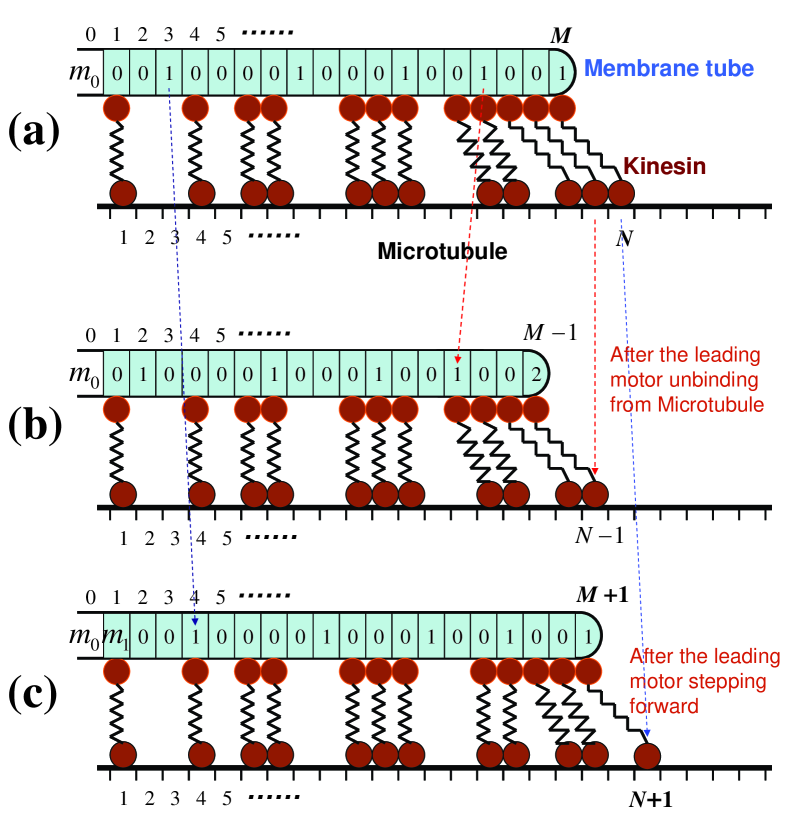
Noticing the finite volume of the complex of motor tail domain and streptavidin. The tail domain complexes of neighboring motors may exclude each other, and generate repulsive force in between. In this way, the non-leading motors can also apply force to the leading motor and thus to the membrane tube. On the other hand, the elasticity of the stalk of kinesin molecule has been found to play an interesting role in multi-motor transportation in our previous study wang.09 . In the present paper, the kinesin stalk is also considered as a spring, with an elastic constant . Combining the above two points, one can picture the kinesin molecule as a dumbbell with a spring-like stalk (Fig. 1). One end of the dumbbell (the tail domain) can slide on the surface of the membrane tube, and can not detach from membrane tubes because of strong connection between kinesin and lipid. The other end of the dumbbell (the head domain) can either bind to or unbind from the microtubule, and the bound motor can step forward with a rate or detach from the microtubule with a rate
| (1) |
where is the unbinding rate at vanishing load, and is the detachment force with the value of about 3.0 pN klumpp.05 . The backward stepping of motor is neglected here. The motors which attach to the membrane tube but not bind to the microtubule (i.e., free motors), can diffuse freely on the surface of membrane tube with a diffusion constant and bind randomly at a rate to non-occupied sites on the microtubule.
To carry out a simulation of the tube growth (Sec.III), we have adopted a discrete microscopic approach in which the membrane tube is discretized into sites (called membrane sites) numbered from 0 to (Fig. 1), and the lattice spacing equals to the periodicity of microtubule, 8nm. The boundary membrane site 0 is connected to the reservoir of motors (the lipid vesicle) which can supply motors continuously when membrane tube is growing, and the motor density at this site is , i.e. the motor density on the vesicle. So the number of motors on membrane site 0 is , where the radius of membrane tube is related to the retreating force and the bending modulus of the membrane by juli.02 . Since the whole perimeter of the tube exceeds 60 nm, each membrane site can contain many motors. In our simulations, however, we find that the number of free motors at a given membrane site seldom exceeds two, which means the free motor density is so low that their diffusion is almost uncorrelated. So the diffusion rate of a free motor along the membrane tube can be taken as camp.08 . A bound motor steps forward to the next un-occupied microtubule site with a rate , where is the force-velocity function for single motor transport which has been widely studied both experimentally and theoretically carter.05 ; fisher.01 . In this study, the function is adapted from theoretical results of two-state stochastic model of Fisher and Kolomeisky, with [ATP]=1.0 mM (see Ref. fisher.01 for details).
We now turn to the tip of membrane tube. Each bound motor behaves just like a spring connecting two beads. One bead (the head domain) binds to the microtubule, while the other (the tail domain) connects tightly to the membrane tube. If a motor bears force, the spring is stretched. In this model, the loading force is directly transmitted to the leading bound motor. The following motors can also share the load, by pushing the leading motor due to the exclusion of their tail domains (Fig. 1). In fact, most of the tip motors would bear the load. For instance, head domains of two neighboring motors may be separated by one or more empty microtubule sites, but their tail domains can still interact with each other since their stalks can be stretched (see Fig. 1(a), the five leading motors on the tip will share the load). Motors which bear the load are called pulling motors. The length of membrane tube is determined by the equilibration between retreating force and extracting force which depends on the distribution of bound motors on the microtubule.
If a motor unbinds from the microtubule, it can diffuse on the surface of the membrane tube (Fig. 1(b)). If a motor steps forward on the microtubule, its tail domain will be dragged forward (Fig. 1(c)). For an unpulling motor, the tail domain is usually dragged forward by one membrane site after a forward step, and it does not change the tube length and the state of other motors. But an unpulling motor can also become a pulling motor when it encounters another pulling motor after a forward step. Then the load should be redistributed among pulling motors.
III Simulation Algorithm
We adopt the Gillespie algorithm gil.76 to simulate the growth process of the membrane tube, based on the model introduced in Sec. II.
As mentioned, each bound motor can unbind from microtubule and step forward, and the free motors can diffuse and bind to microtubule. In the simulation, we define an array numbered in order , which represent all the transition rates of the system if the excluded volume effect between the motors is not considered.
| (2a) | |||||
| (2b) | |||||
| (2c) | |||||
| (2d) | |||||
| (2e) | |||||
| (2f) | |||||
where indicates the microtubule site occupied by the leading motor, is the total length of the membrane tube. Noting that are not fixed numbers but vary with the process of tube growth. is the number of bound motor at microtubule site , which is either 0 or 1. is the number of free motor at membrane site . is the number of motor at membrane site 0, and represents the diffusion rate of the motor from membrane site 0 (i.e., the reservior) to site 1.
corresponds to the unbinding rate of the motor from microtubule site , corresponds to the forward stepping rate of the motor at microtubule site . , correspond respectively to the backward and the forward diffusion rate of a free motor at membrane site . corresponds to the binding rate of a free motor at membrane site to the microtubule.
Considering the excluded volume effects, some of the above transitions are actually prohibited, so the corresponding transition rates must be 0, or else . Especially, because the free motors at membrane site can not diffuse forward.
We define the global transition rate as
| (3) |
In Gillespie algorithm, the time step is not fixed and is a stochastic variable distributed exponentially with a characteristic time scale . determines how long to wait to see a motor (no matter on which site) performing any one of the above mentioned transitions. To determine which transition will take place in the next time step, we generate a random number distributed uniformly in the range . The largest value of that fulfills the following inequality,
| (4) |
means that the -th transition numbered in Eq. 2 will occur in the next time step.
The simulation is performed as follows. The initial length of the membrane tube is set as with each site occupied by a bound motor, and the actual transition rates are calculated. Then the following steps are repeated.
(1) Calculate the global transition rate , and determine the stochastic time step .
(2) Determine which transition to take place. In this step, one of the following four possible cases may be encountered.
a) A bound motor unbinds from the microtubule. So the number of free motors at the corresponding site of the membrane tube will increase by one. If this unbinding motor is a pulling motor, the load will be redistributed by other motors according to the equilibration of force, and the length of the membrane tube will also be changed too.
b) A bound motor steps forward. Its tail domain will be dragged forward. If it is a pulling motor, the load will be redistributed among pulling motors, and the length of the membrane tube will be changed too. Sometimes an unpulling motor can become a pulling motor after a forward step, as mentioned in Sec. II.
c) A free motor diffuses from one membrane site to another.
d) A free motor at membrane site binds to the microtubule, then , .
(3) After one of the above four cases performed, the array is updated with the new configuration.
(4) The time is updated to and the process is repeated.
The repetition stops when it reaches the conditions that we set up, which will be explained in the following.
| Parameter | ||||||
|---|---|---|---|---|---|---|
| Value | 0.3 pN/nm | 3.0 pN | 1 m2s-1 | 4.7 s-1 | 0.42 s-1 | 10 |
| Ref. | cop.97 | klumpp.05 | leduc.04 ; camp.08 | leduc.04 ; camp.08 | camp.08 ; vale.96 | leduc.04 ; camp.08 |
At a constant motor density , there exist a threshold retreat force above which the motors cannot extract a membrane tube from the vesicle. The is determined as follows camp.08 . For a given value of the motor density , we initially set the retreating force a very large value and repeat this process 200 times. If the force is too large, the membrane tube may retreat completely. If membrane tube retreat can be observed in all the 200 cases, we lower the force and repeat the process again till a threshold value is reached, at which at least one among the 200 membrane tubes does not retreat. Typically, membrane tube retreat usually occurs when , and seldom occurs when . In our simulation, if the length of the membrane tube exceeds (i.e. m), the membrane tube can grow persistently and no retreat can be observed, so we set as the threshold value which means the forming of a membrane tube.
To calculate the growth velocity of membrane tube, we let the membrane tube grows to a long enough length, 6.4 m. Since the system is not in steady state at the beginning, we calculate the average growth velocity when the length of the membrane tube is in the range from 0.4 to 6.4 m.
IV Results and Discussion
IV.1 The growth of membrane tube
In Ref. leduc.04 ; camp.08 , experiments showed that there exists a threshold value of motor density below which the motors cannot extract membrane tubes from the vesicle at a given extraction force . It means that at a constant motor density , the motors cannot pull a membrane tube if the retreat force is larger than a threshold force . If - relation is known, we can predict the threshold density above which membrane tubes can be extracted from vesicles. In order to compare our results with Ref. camp.08 , we use the same parameters as Ref. camp.08 , which are listed in Table. 1. And we also adopt the same method to find the threshold force as Ref. camp.08 has done, as mentioned in Sec. III.
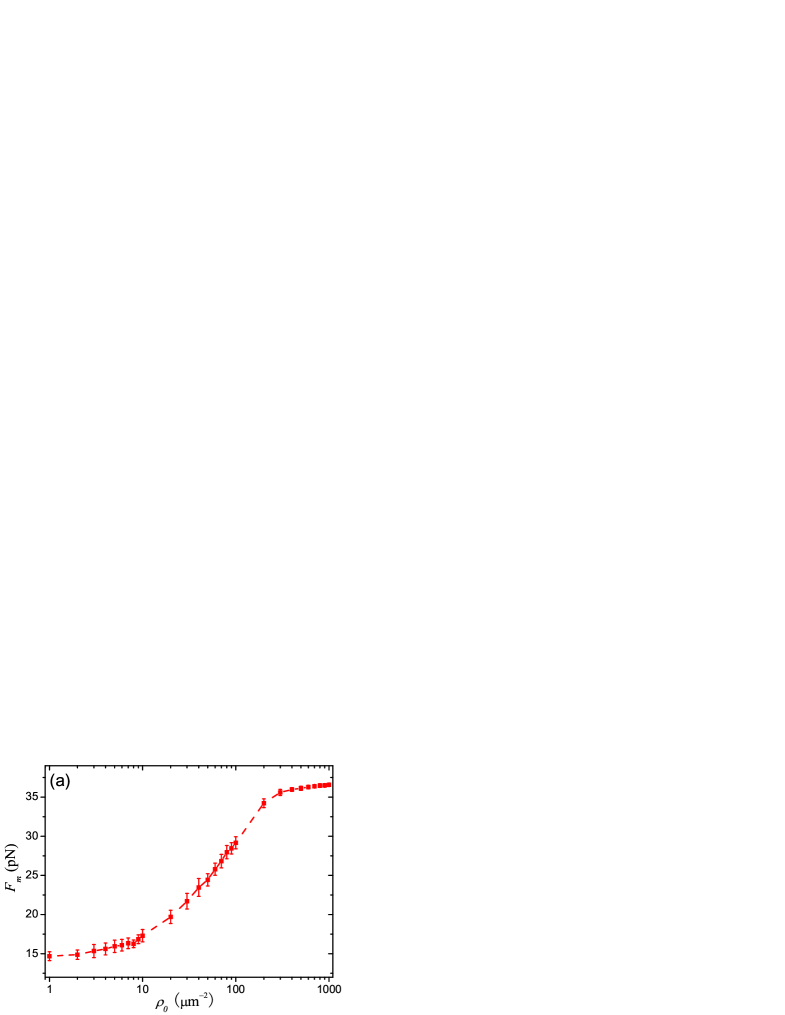
In Fig. 2(a), we plot the simulated - relation. The force increases with from 14 (corresponding to m-2) to 36 pN (corresponding to m-2). In the experiments, the actual extraction force for membrane tube is found about pN leduc.04 . From Fig. 2(a), we can know the corresponding threshold value of to extract membrane tubes from vesicles is about m-2, which agrees quite well with the experiment values about 100200 m-2 leduc.04 ; camp.08 .
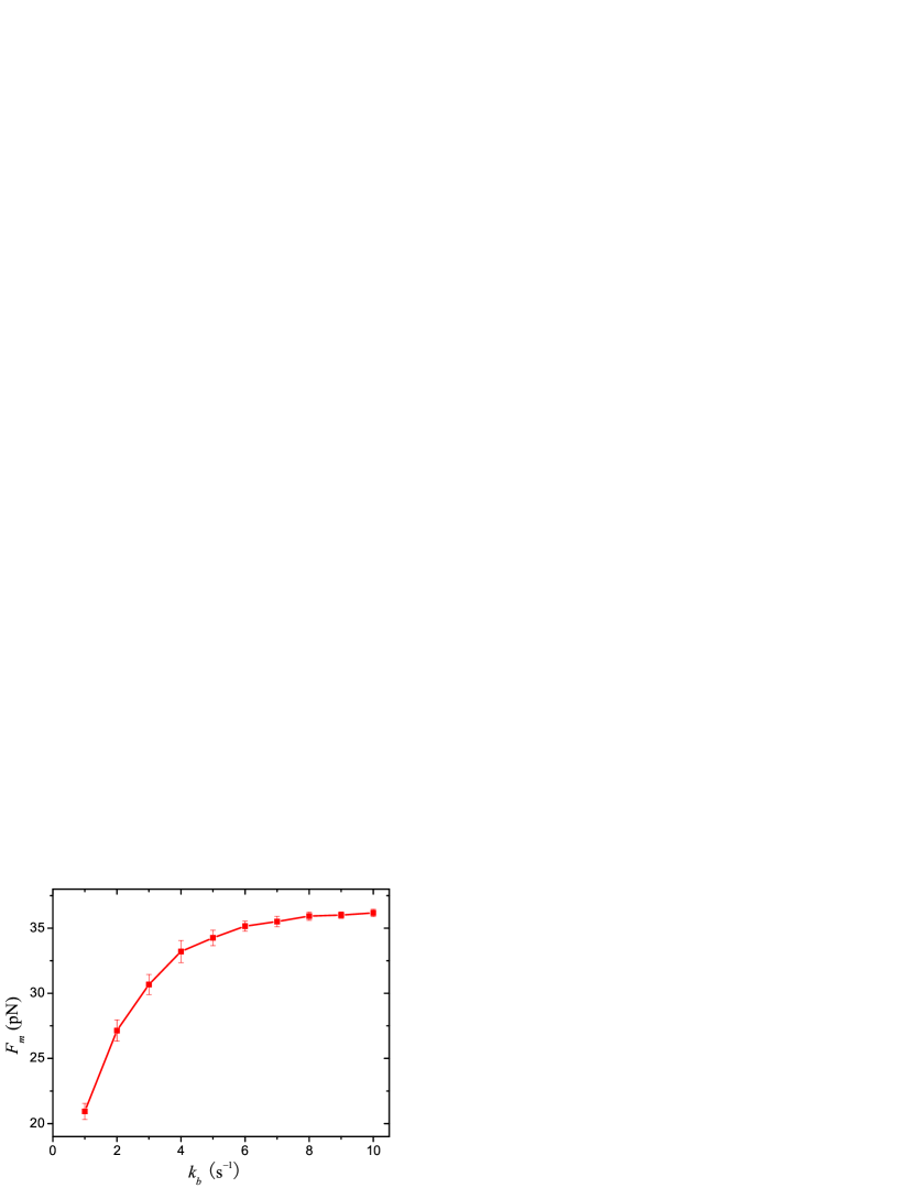
In Table. 1, all the parameters but the binding rate , are adapted from experiments. s-1 is a fitting value from Ref. leduc.04 , and its reliability would be questioned. In Fig.3, we plot the -dependence of at m-2. increases fast with when is smaller than 4.0 s-1, and then increase slowly to a saturated value about 36 pN. When s-1, will be larger than 27.5 pN, which is big enough to extract membrane tubes from a vesicle.
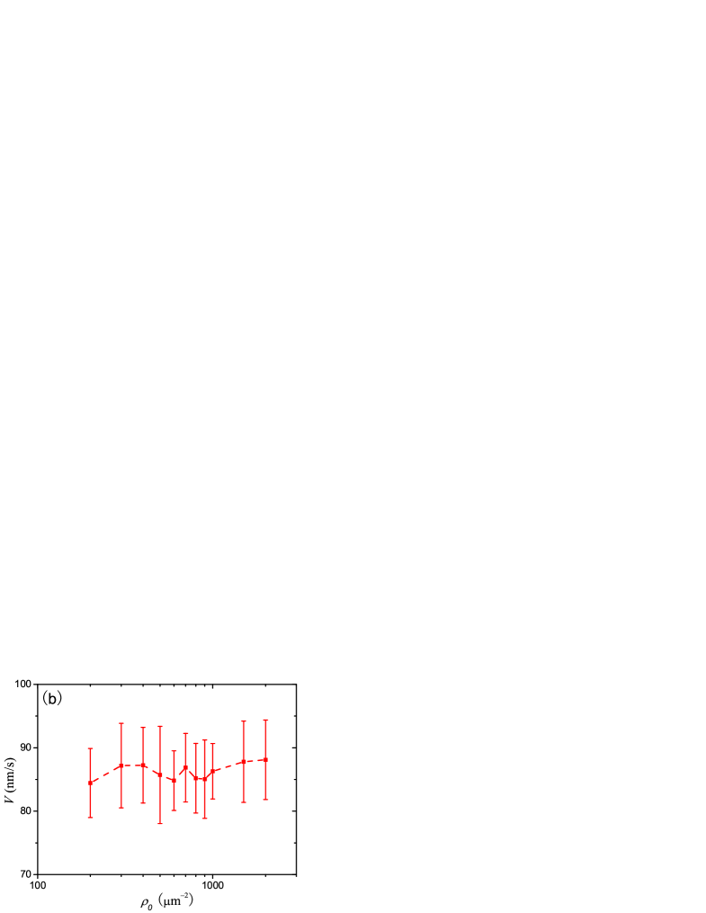
The growth velocity of membrane tubes as a function of , at the given load of 27.5 pN, is shown in Fig. 2(b). The mean velocity is about nm/s, consistent with the experiment value nm/s. The almost independence of the mean velocity on is a prediction which can be tested by further experiments.
IV.2 The distribution of motors
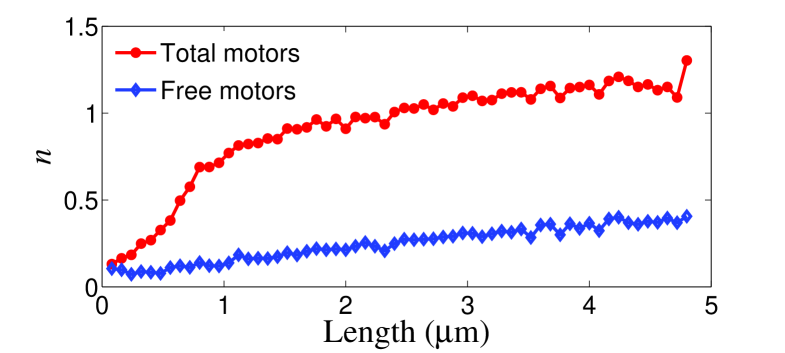
In Ref. leduc.04 , the motors are found not uniformly distributed along the membrane tube. At the tip region, the density is bigger than that of the rest of the membrane tube. Our simulation results are in agreement with this observation. Fig. 4 shows that the mean density of motors increases from the vesicles to the tip of membrane tube. Because the motors in the tip region bear the load, their velocities are smaller than the motors in the rest region, so the motors will accumulate in the tip region and generate enough force to extract the membrane tube. Especially at the very tip of the membrane tube, almost each microtubule site is occupied by a bound motor. Moreover, there are free motors on the membrane tube, so the motor density in this region exceeds 1 per site. Since the motors in the tip region unbind from microtubule more frequently than that of other region due to high load, the density of free motors in the tip region is also higher than that of other region as shown in Fig. 4. These free motors will diffuse and rebind to the microtubule, and then step toward the tip region again, forming a cycle of motor flow.
At the tip region of membrane tube, the number of pulling motors is also a stochastic variable which fluctuates during membrane tube growth. We now study the number of pulling motors and its probability distribution.
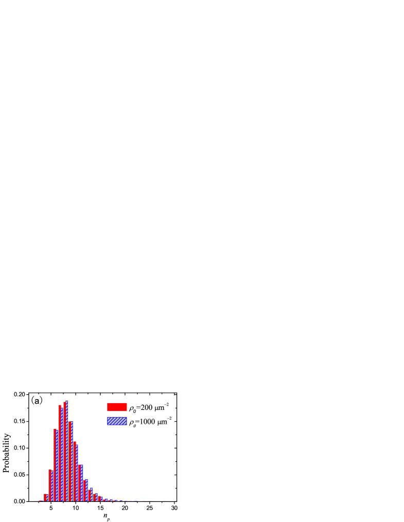
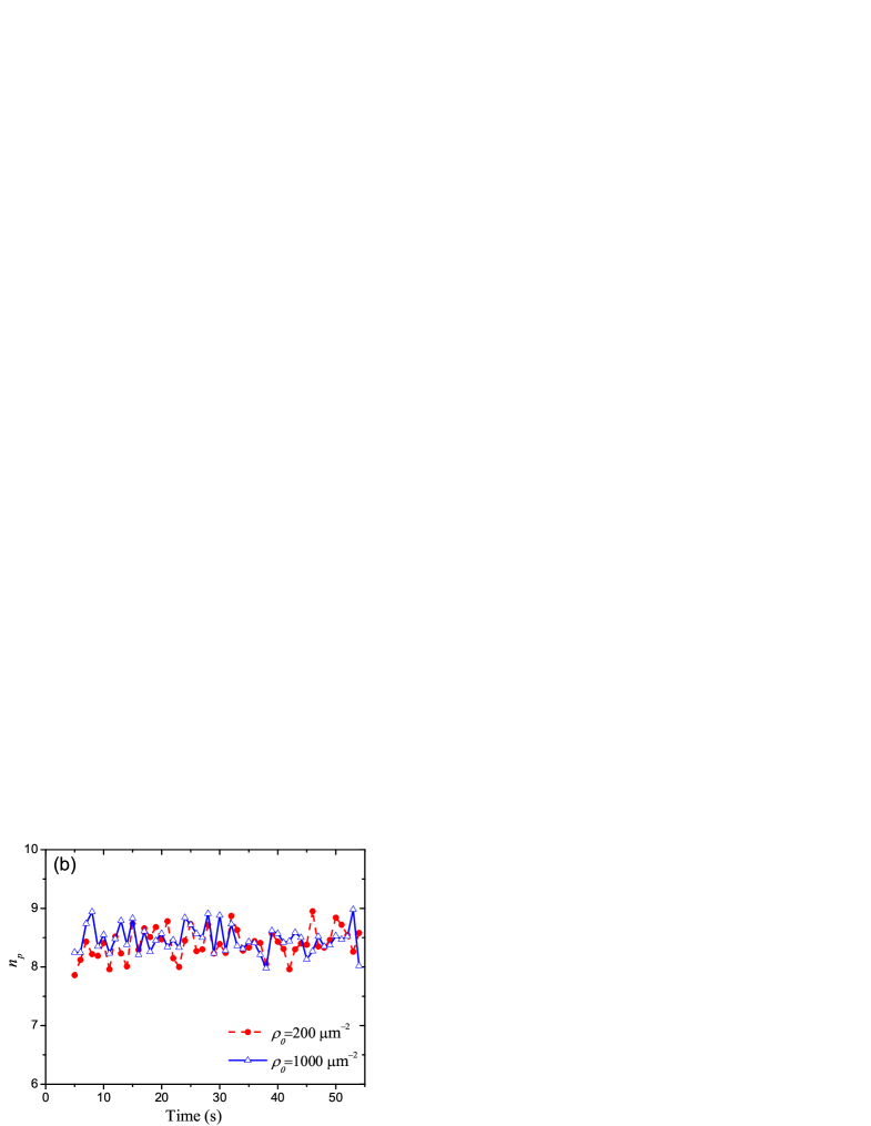
In Fig. 5(a) we plot the probability distributions of pulling motor number for two different motor densities, m-2 and m-2 respectively. The data are obtained from 100 independent simulated membrane tubes, and 100 samples are picked out from each membrane tube at 0.5-second intervals during its growth, so there are 10000 samples for either . Since successive samples are separated sufficiently long time, they can be regarded as independent samples, so we can plot the histogram Fig. 5(a). During membrane tube growth, the average number of pulling motors is 8.4 and 8.5 for m-2 and m-2 respectively. The average number of pulling motors can be regarded as a time-independent constant, as shown in Fig. 5(b). So the number of puling motors is almost independent of motor density and the length of membrane tube. On average, in the growth of membrane tube, each pulling motor bears pN, which smaller than the stall force of kinesin, about 7pN.
V Summary and conclusion
In this paper the mechanism of extracting membrane tubes by motors is studied. We propose a two-track-dumbbell model, by considering the excluded volume effect of both the head domain and tail domain of motors, as well as the elasticity of the motor stalk. We conclude that (1) the membrane tube can be extracted by a group of motors along a single microtubule protofilament; (2) the growth velocity of the membrane tube is almost independent of the motor densities on the vesicle ; (3) the density of motors in the tip region is much higher than that in the root region.
(2) is a prediction, (3) agree with experimental data leduc.04 , and (1) is in contrary to the result of Ref. camp.08 which suggested that motors use several protofilaments simultaneously to pull a single tube, without consideration of the structure and elasticity of the motor molecule. While these properties, especially the elasticity of motor stalks, can affect the multi-motor transport wang.09 , it’s also understandable they play a role in extracting membrane tubes by a collect of motors. Our simulation results show that the number of pulling motors (which apply force against the retraction of membrane tube) at the tip region of membrane tube is about and thus they can generate enough force to extract a membrane tube from a vesicle and maintain its growth, while Ref. camp.08 indicates the number of pulling motors is about 3 and thus three protofilaments are necessary to extract a membrane tube.
Another difference between our model and Ref. camp.08 , the choice of force-velocity (F-V) relation of a single motor, may influence the simulation results too. In Ref. camp.08 , the (F-V) relation of a single motor is simplified as linear, while we adopt the more reliable theoretical relation from Ref. fisher.01 . In our previous study, we have shown that the property of multi-motor transport strongly depends on the F-V relation of a single motor wang.09 . Hence, whether the membrane tube is pulled by one row or several rows of motors, and how the intrinsic properties of kinesin motors (the elasticity of kinesin stalk, the excluded volume effect, and the characteristic F-V relation of a single motor) are involved in the extracting process, should be investigated by future experiments.
ACKNOWLEDGMENTS
Z. Q. Wang thanks the support of NSFC under Grant No. 11047188, and Chinese Universities Scientific Fund under Grant No. QN2009046. M. Li thanks the support of NSFC under Grant No. 11075015.
References
- (1) C. Lee and L. B. Chen, Cell 54, 37 (1988).
- (2) N. Sciaky, J. Presley, C. Smith, K. J. M. Zaal, N. Cole, J. E. Moreira, M. Terasaki, E. Siggia, and J. Lippincott-Schwartz, J. Cell Biol. 139, 1137 (1997).
- (3) V. Allan and R. Vale, J. Cell Sci. 107, 1885 (1994).
- (4) A. Roux, G. Cappello, J. Cartaud, J. Prost, B. Goud, and P. Bassereau, Proc. Natl. Acad. Sci. U.S.A. 99, 5394 (2002).
- (5) G. Koster, M. VanDuijn, B. Hofs, and M. Dogterom, Proc. Natl. Acad. Sci. U.S.A. 100,15583 (2003).
- (6) C. Leduc, O. Campas, K. B. Zeldovich, A. Roux, P. Jolimaitre, L. Bourel-Bonnet, B. Goud, J. F. Joanny, P. Bassereau, and J. Prost, Proc. Natl. Acad. Sci. U.S.A. 101, 17096 (2004).
- (7) P. M. Shaklee, T. Idema, G. Koster, C. Storm, T. Schmidt, and M. Dogterom, Proc. Natl. Acad. Sci. U.S.A. 105, 7993 (2008).
- (8) P. M. Shaklee, L. Bourel-Bonnet, M. Dogterom, and T. Schmidt, Biophys. J. 98, 93 (2010).
- (9) I. Derényi, F. Jülicher, and J. Prost, Phys. Rev. Lett. 88, 238101 (2002).
- (10) N. J. Carter and R. A. Cross, Nature (London) 435, 308 (2005).
- (11) M. E. Fisher and A. B. Kolomeisky, Proc. Natl. Acad. Sci. U.S.A. 98, 7748 (2001).
- (12) F. Jülicher and J. Prost, Phys. Rev. Lett. 75, 2618 (1995).
- (13) S. Klumpp and R. Lipowsky, Proc. Natl. Acad. Sci. U.S.A. 102, 17284 (2005).
- (14) Z. Q. Wang and M. Li, Phys. Rev. E 80, 041923 (2009).
- (15) O. Campàs, Y. Kafri, K. B. Zeldovich, J. Casademunt, and J.-F. Joanny, Phys. Rev. Lett. 97, 038101 (2006).
- (16) J. Brugués and J. Casademunt, Phys. Rev. Lett. 102, 118104 (2009).
- (17) O. Campàs, C. Leduc, P. Bassereau, J. Casademunt, J.-F. Joanny, and J. Prost, Biophys. J. 94, 5009 (2008).
- (18) D. T. Gillespie, J. Comp. Phys. 22, 403 (1976).
- (19) C. M. Coppin, D. W. Pierce, L. Hsu, and R. D. Vale, Proc. Natl. Acad. Sci. U.S.A. 94, 8539 (1997).
- (20) R. D. Vale, T. Funatsu, D. W. Pierce, L. Romberg, Y. Harada, and T. Yanagida, Nature 380, 451 (1996).