A New Mirror Alignment System for the VERITAS Telescopes
Abstract
Imaging atmospheric Cherenkov telescopes (IACTs) used for ground-based gamma-ray astronomy at TeV energies use reflectors with areas on the order of 100m2 as their primary optic. These tessellated reflectors comprise hundreds of mirror facets mounted on a space frame to achieve this large area at a reasonable cost. To achieve a reflecting surface of sufficient quality one must precisely orient each facet using a procedure known as alignment. We describe here an alignment system which uses a digital (CCD) camera placed at the focus of the optical system, facing the reflector. The camera acquires a series of images of the reflector while the telescope scans a grid of points centred on the direction of a bright star. Correctly aligned facets are brightest when the telescope is pointed directly at the star, while mis-aligned facets are brightest when the angle between the star and the telescope pointing direction is twice the misalignment angle of the facet. Data from this scan can be used to calculate the adjustments required to align each facet. We have constructed such a system and have tested it on three of the VERITAS IACTs. Using this system the optical point spread functions of the telescopes have been narrowed by more than 30%. We present here a description of the system and results from initial use.
keywords:
VERITAS, IACT, Alignment, Optics1 Introduction
The current generation of imaging atmospheric Cherenkov telescopes operating around the world [1, 2, 3] has ushered in a new era in TeV gamma-ray astronomy. The number of detected TeV gamma-ray sources has grown from below ten in 2000 to more than seventy today [4] largely because of the increased sensitivity of the instrumentation. This increase results from the use of the following:
-
1.
larger reflectors
-
2.
cameras with larger fields of view and higher resolution
-
3.
multiple telescopes making stereoscopic observations
-
4.
flash-ADC-based data acquisition systems
For the benefits afforded by large reflectors and high resolution cameras to be fully realised, the optical quality of the telescopes must be maintained at a high level. Since the reflectors of these telescopes comprise several hundred mirror facets, their alignment presents a significant technical and logistical challenge.
The VERITAS array, located in southern Arizona, USA, employs four twelve-metre-diameter f-1.0 reflectors of the Davies-Cotton type [5]. Each reflector consists of a tubular steel optical support structure (OSS) on which 345 identical hexagonal mirror facets are mounted. The facet mounts allow precision adjustments to bring the focus of each to the same point on the primary focal plane of the telescope. Since the mirror facets are exposed to the dust of the Arizona Sonoran desert their reflectivity degrades over time so they are therefore re-coated on a regular basis [6]. This process maintains the reflectivity of the facets but their removal and re-installation compromises the optical quality of the reflector as a whole so the alignment of the facets must be repeated on a regular basis.
We present here an alignment system, based on the technique originally suggested by Arqueros et al. [7], which can be used for aligning the VERITAS telescopes. It achieves the quality desired in a reasonable length of time at modest cost. Importantly, the optimal alignment is achieved for typical observation elevations.
2 Method and Apparatus
Our alignment system uses a digital camera which is mounted at the centre of the telescope’s focal plane, facing the reflector. Images of the reflector are acquired at each point of a raster scan that the telescope performs centred on a bright star at a typical observing elevation. At each point in the raster scan, the camera registers the amount of light from each facet; the point in the scan at which a given facet appears brightest occurs when the angle between the pointing direction of the telescope and the star is exactly twice the mis-alignment angle of the facet (see Figure 1). On completion of the raster scan the acquired images are analysed and correction adjustments are calculated for each facet.


A photograph of the alignment apparatus is shown in Figure 2. The apparatus consists of:
-
1.
a mounting plate
-
2.
an x-y positional stage
-
3.
a 45∘ plane mirror
-
4.
a digital camera with wide-angle lens
-
5.
a notebook computer
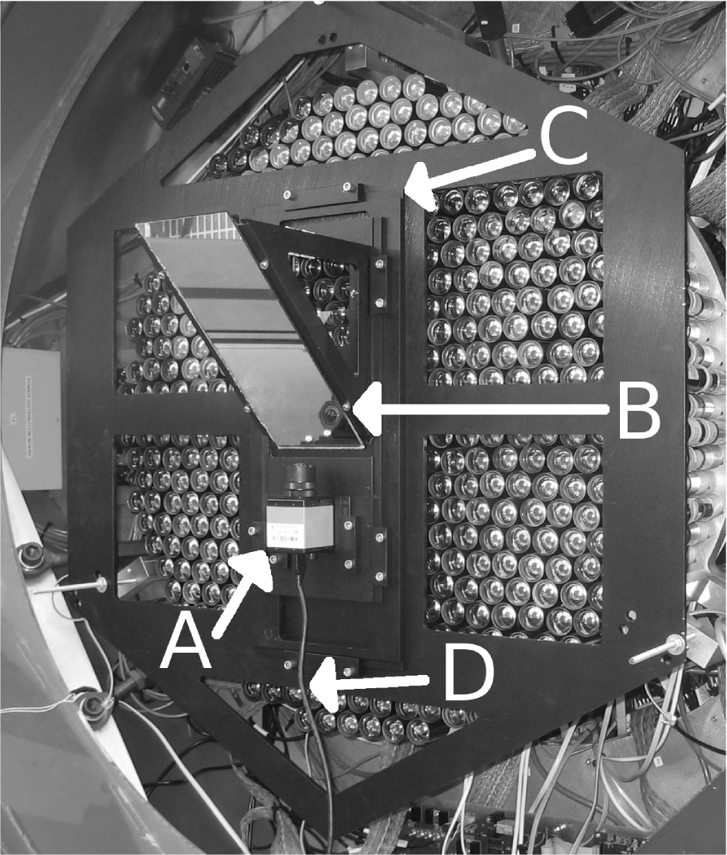
The mounting plate is constructed from 6-mm anodised aluminum and has several large cut-outs to reduce its weight. It enables quick and reproducible installation on any of the VERITAS telescopes with no modifications to the photomultiplier tube (PMT) camera required. The camera and plane mirror are mounted on the x-y positional stage which allows the camera’s virtual image in the 45∘ mirror to be located on the telescope’s optical axis at the prime focus of the reflector. The camera, model DMK 21BF04 from Imaging Source, is based on a 1/4-inch, 640480 pixel, monochrome CCD device. The wide-angle f-1.4 lens is a Computar T2314-FICS-3 with a 2.3 mm focal length and a 22.8 mm effective front aperture.
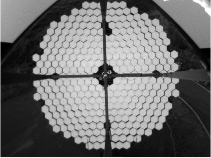
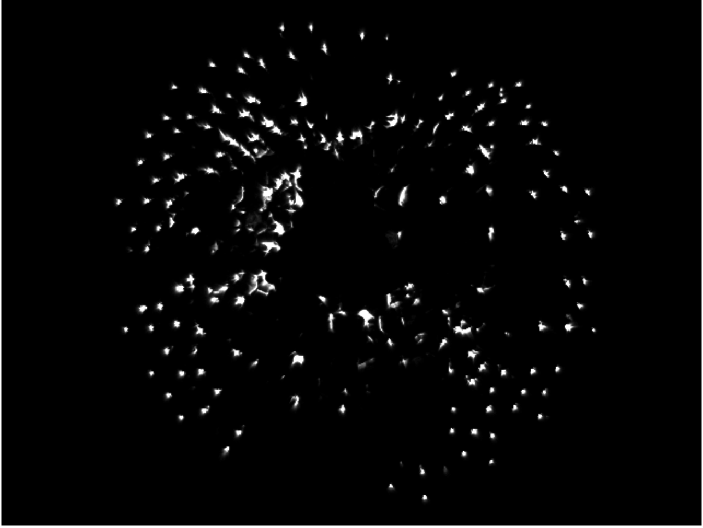
Image acquisition software runs on a notebook computer which is connected to the camera via a firewire interface and to the telescope tracking computer via ethernet. Images are stored in the FITS data format [8] with the telescope pointing information saved in the image metadata. Two images of the telescope reflector, taken with the alignment camera, are displayed in Figure 3.
3 Data acquisition and analysis
The first stage of the data acquisition process is the recording of a template image: an image of the reflector fully illuminated with all facets clearly visible (see Figure 3a). This image is used to map between the pixels of the CCD camera and the facets of the reflector. More precisely, a circular region inside each facet, encompassing 90% of the CCD pixels associated with the facet, is selected. In the analysis of all subsequent images the signal in these pixels is assumed to be caused by light reflecting off the corresponding facet. The signal in the remaining 10% of the facet is ignored in the analysis. This region may be illuminated by light reflecting off the edge of the facet or may be contaminated by the signal from pixels illuminated by the neighbouring facet bleeding across the CCD. A template must be recorded every time the alignment system is mounted or adjusted in order to ensure that the mapping between the CCD pixels and the reflector facets is accurate. An image of a VERITAS reflector, taken at twilight, is used as the template image for data acquired during the following night. In cases where the raster-scan data are acquired after a partial night of standard gamma-ray observations, the template image is acquired with the moon illuminating the reflector.
The second stage of the data acquisition consists of capturing successive images of the reflector while the telescope performs a raster scan centred on a star of magnitude 3 or brighter. In the tests presented here we used stars which transited at an elevation of 70∘ and tracked them for two hours, with tracking beginning one hour before culmination. This ensured that the entire scan was performed over a small elevation range ( 5∘). This is necessary because the OSS deforms slightly under gravity as the telescope moves in elevation so categorisation and optimisation of the telescope’s optics should be performed over a range of elevations close to those used for most astronomical observations.
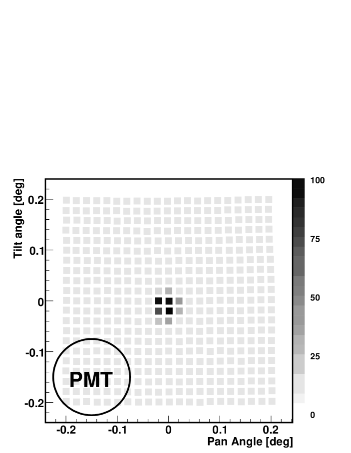
The raster scans used for the tests reported on here were performed over a grid of 2121 pointings, on the plane tangent to the right ascension and declination of the chosen star. The angular spacing between each row and column in the grid was 0.02∘. A program running on the telescope’s tracking computer was used to slew the telescope to the required grid coordinate. A pause of three seconds was then observed, to allow any post-slewing oscillations of the telescope to die out, before the CCD camera was commanded to capture an image of the reflector. Once the capture process was completed the telescope was slewed to the next grid point. This combination of grid size, grid resolution and telescope settling time was chosen to allow a scan which could be completed in two hours and which scanned an area fully encompassing the point-spread-function (PSF).
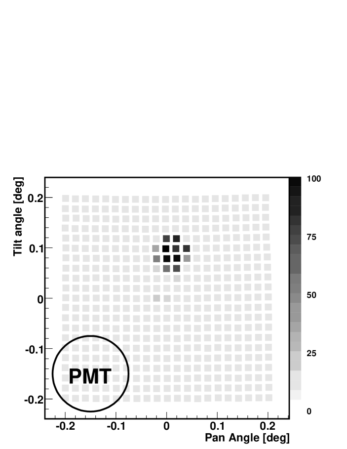
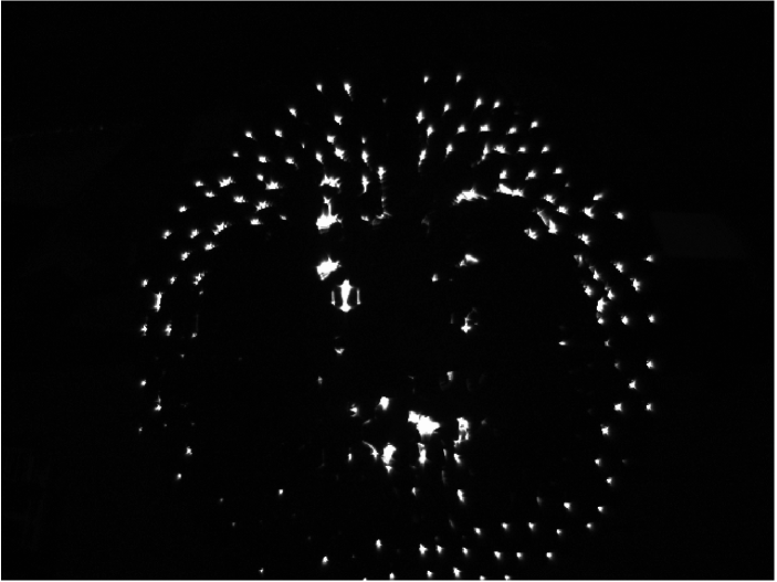
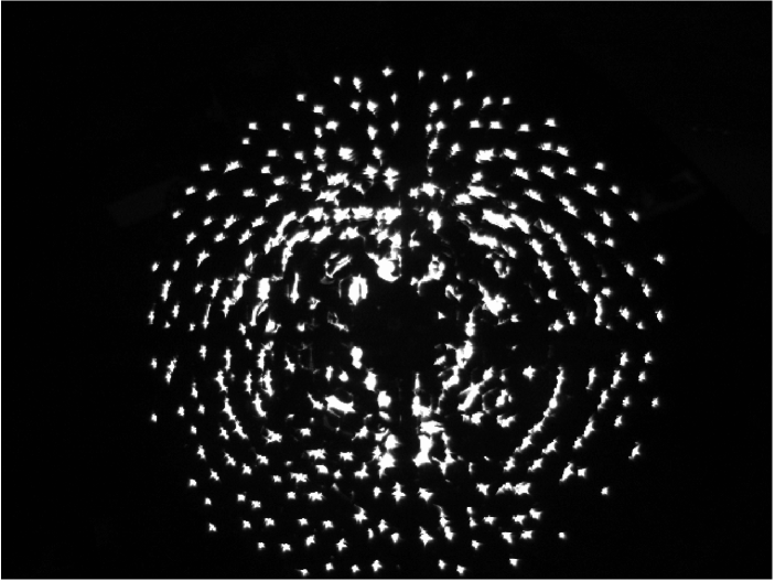
The images of the reflector, captured during the scan, are analysed in the following way. For each image, a brightness value is assigned to every facet. The brightness value associated with a given facet is calculated by summing the signal in the pixels which correspond to the facet, as determined from the map generated from the template image. These brightness values are then plotted at the corresponding scan points in a two-dimensional map (see Figure 4 for examples). The scan point with the maximal brightness for a given facet identifies the mis-alignment angle of the facet. The telescope pointing offset for that scan point corresponds to twice the mis-alignment angle since the angle of incidence and angle of reflection of the starlight change together.
In practice, the positioning of the alignment apparatus on the telescope optical axis is not perfect. This leads to a small systematic bias in the calculated mis-alignment angles which manifests itself as a non-zero value for the the mean of all mis-alignment angles. This bias is subtracted from the mis-alignment angles when computing the alignment adjustment values.
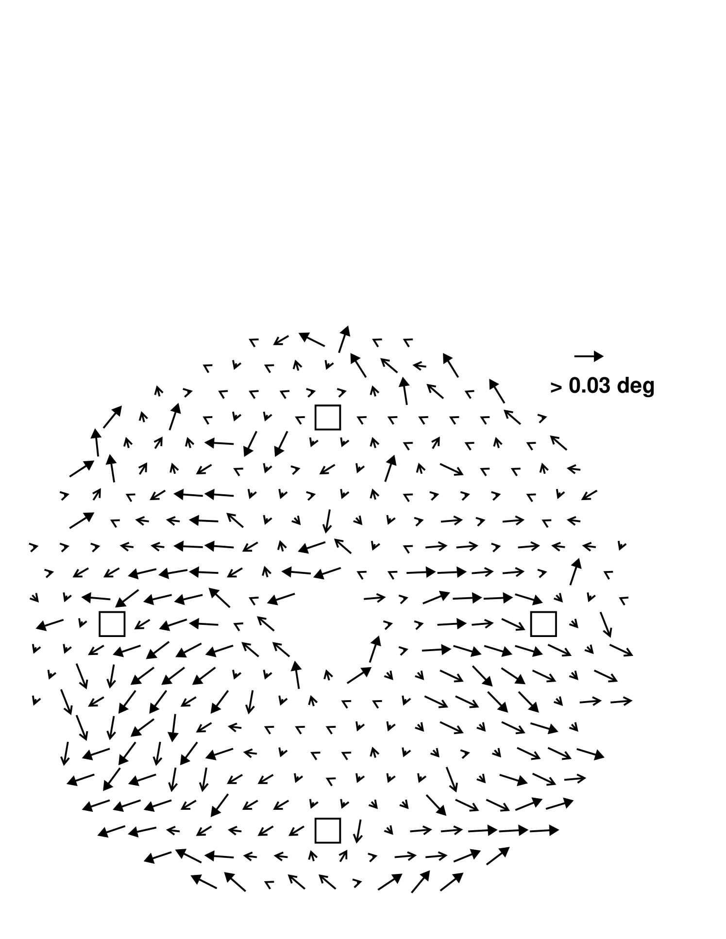
The mis-alignments determined from a raster scan can be summarised in a single plot, as shown in Figure 5.
4 Correction Implementation
Each mirror facet of a VERITAS reflector is supported by a triangular three-point suspension. At each vertex, a brass mounting gimbal and adjustment nut are threaded onto a stainless-steel threaded rod. Any mis-alignment of the facet can be corrected by turning two of these adjustment nuts. The mirror-mount geometry and threaded-rod pitch are such that one full turn on a nut changes the mirror orientation by 0.1∘. The adjustments computed from the raster scan data were implemented on the VERITAS mirrors manually with a socket-wrench device which had a circular index wheel attached to it. This allowed adjustments as small as 1/16th of a turn (0.007∘) to be accurately implemented.
The adjustments were implemented during daylight hours following the raster scan procedure. Experience shows that tuning up an already nominally aligned telescope following the replacement of 50 facets takes only a few hours.
5 Alignment results
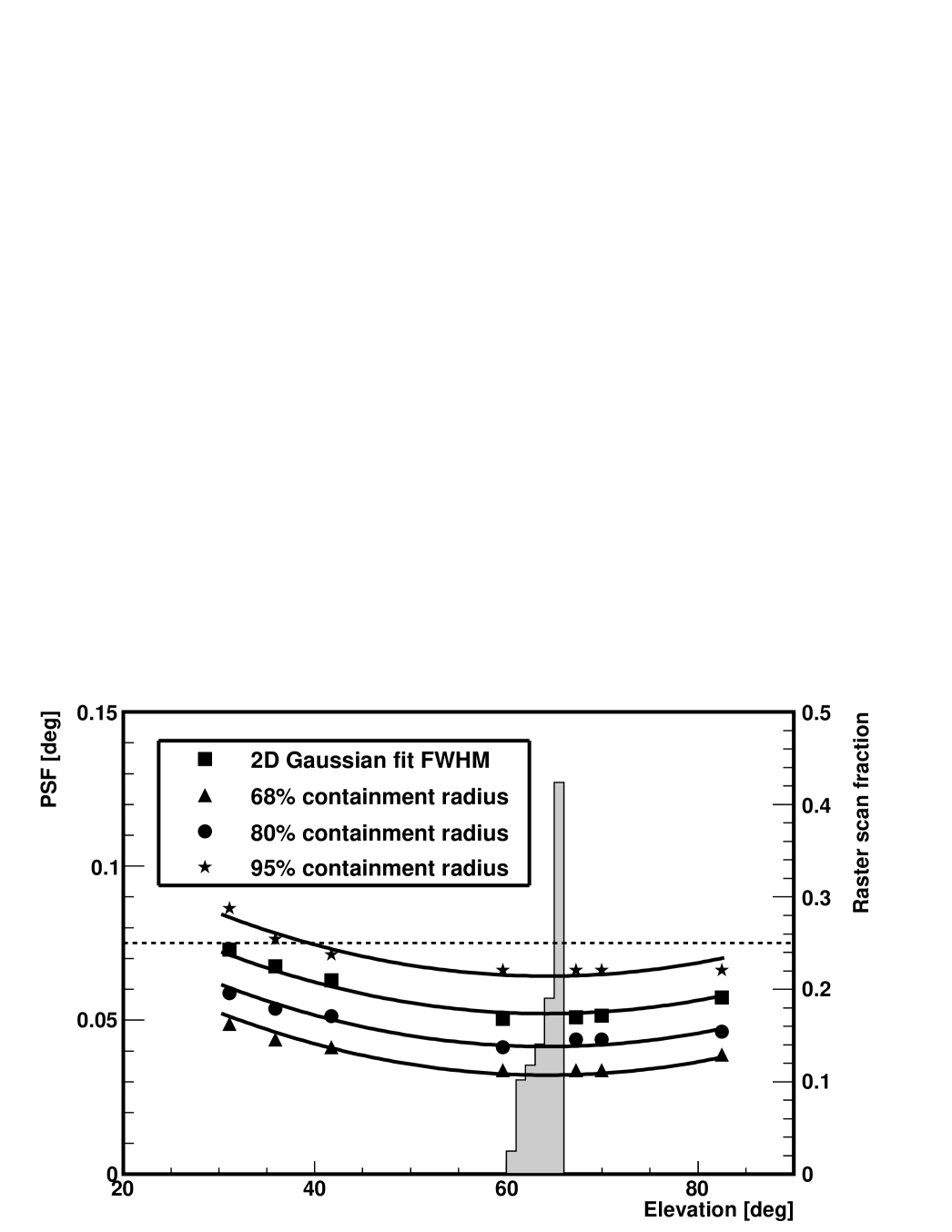
The optical quality of the VERITAS telescopes has improved with the implementation of this alignment system. Three of the four telescopes were aligned during May, 2009 (the fourth was being dismantled for relocation at that time) and the size of the PSF was reduced by more than 30% from previous values. The 80% containment radii of the PSFs are now less than 0.05∘ at operational elevations.
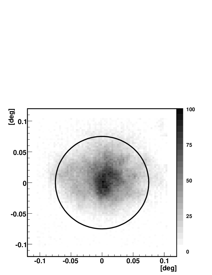
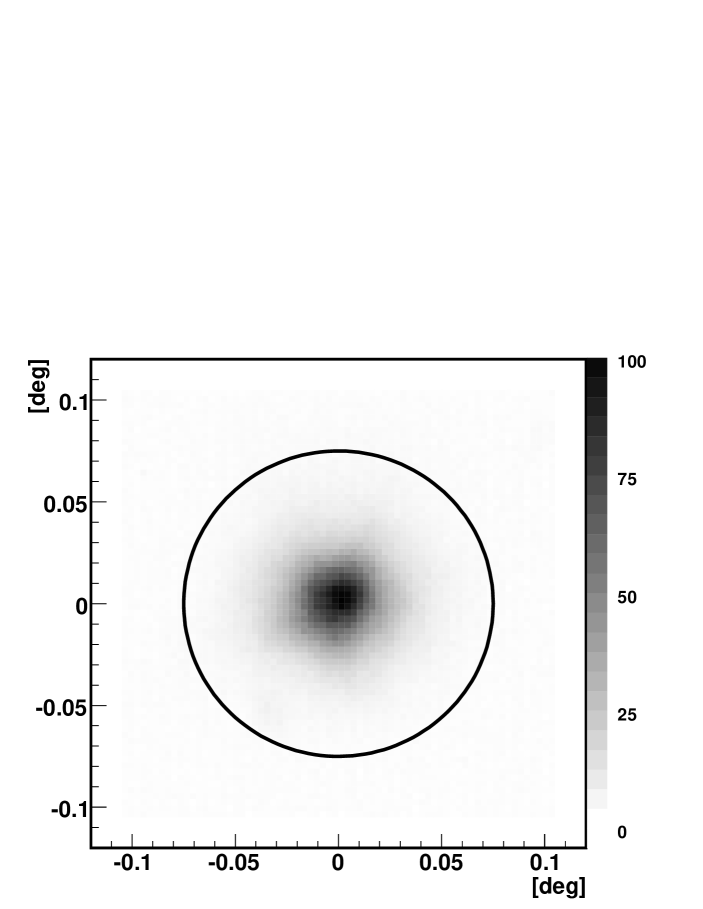
Images of the PSF for a telescope, before and after the alignment, are shown in Figure 6. This figure also displays corresponding images of the reflector, captured by the alignment camera, while the telescope was tracking a bright star, before and after the alignment corrections were applied. Qualitative improvement is evident. The size of the PSF against elevation after the alignment for one of the telescopes is plotted in Figure 7, illustrating the elevation dependence of the PSF. The elevation range over which the raster scan was performed coincides with the elevation of the smallest PSF size, as expected.
6 Discussion
The implementation of this alignment method has proven to be successful. The raster scan can be completed in two hours and the data categorising the facet alignment have been shown to be both useful and accurate. The procedure is much easier to implement than the previous alignment method [9] and is more accurate. Moreover the mirror adjustments can be performed during daylight hours alleviating competition for time working on the telescope. Working during the day is also safer and easier for observatory personnel.
During this initial implementation of the method we have not investigated its limits. We plan further tests in which we will perform raster scans over a grid comparable in size to the now-reduced PSF. We also hope to improve the accuracy with which we can measure the mis-alignment angle by fitting the brightness distribution by a two dimensional Gaussian function and using the fit centroid, rather than the maximally brightened grid point, to identify the angle. To enable us to implement finer facet adjustments anticipated from a high resolution raster scan we have developed a âgearedâ wrench with a ratio of four turns to one. This will allow us to reliably make adjustments as small as 0.0035∘ (corresponding to 1/32nd of a turn of an adjustment nut) to each mirror.
The limiting value of the PSF depends on the positioning of the mirrors, the positioning of the focal plane, the PSFs of the individual facets and the spread in the size of the facet PSFs across the mirror population. Ray-tracing simulations made assuming the nominal telescope design specifications suggest that a PSF with an 80% containment radius of 0.035∘ should be attainable.
Further to improving the PSF, we intend to use the alignment system to better understand the flexure of the telescope OSS. By performing raster scans at several different elevations, the warping of the OSS due to elevation changes can be measured. These measurements may point to possible modifications to stiffen the OSS and lessen the elevation dependence of the PSF.
7 Conclusion
An alignment system based on the technique suggested by [7] has been developed and used to improve the optics of three VERITAS telescopes. This has led to a reduction in the size of the PSF by more than 30%. Moreover this system is less labour-intensive than that which was previously used. It has the advantage that the telescope reflectors are directly optimised for use at typical observing elevations.
Further investigations are planned.
8 Acknowledgements
VERITAS is supported by grants from the US Department of Energy, the US National Science Foundation, and the Smithsonian Institution, by NSERC in Canada, by Science Foundation Ireland, and by STFC in the UK. We acknowledge the excellent work of the technical support staff at the Fred Lawrence Whipple Observatory and the other institutions of the VERITAS collaboration in the construction and operation of the array. In particular we would like to thank the personnel of the Physics Department Machine Shop at McGill University for their part in constructing the alignment tool.
We also gratefully acknowledge contributions from V. Acciari, S. Fegan, K. Gibbs, G. Gillanders, R. Irvin, N. Karlsson, M. Lang, J. Musser, J. Perkins, A. Pichel, and S. Wissel.
References
- [1] J. Holder et al., Status of the VERITAS Observatory, in: F. A. Aharonian, W. Hofmann, F. Rieger (Eds.), American Institute of Physics Conference Series, Vol. 1085 of American Institute of Physics Conference Series, 2008, pp. 657–660. doi:10.1063/1.3076760.
- [2] J. A. Hinton, The status of the HESS project, New Astronomy Review 48 (2004) 331–337. arXiv:arXiv:astro-ph/0403052, doi:10.1016/j.newar.2003.12.004.
- [3] C. Baixeras et al. , Commissioning and first tests of the MAGIC telescope, Nuclear Instruments and Methods in Physics Research A 518 (2004) 188–192. doi:10.1016/j.nima.2003.10.057.
- [4] F. Aharonian, J. Buckley, T. Kifune, G. Sinnis, High energy astrophysics with ground-based gamma ray detectors, Reports on Progress in Physics 71 (9) (2008) 096901–+. doi:10.1088/0034-4885/71/9/096901.
- [5] J. M. Davies, E. S. Cotton, Design of the quartermaster solar furnace, Solar Energy 1:2-3 (1957) 16–22.
- [6] E. Roache, R. Irvin, J. S. Perkins, et al., Mirror Facets for the VERITAS Telescopes, in: International Cosmic Ray Conference, Vol. 3 of International Cosmic Ray Conference, 2008, pp. 1397–1400.
- [7] F. Arqueros, G. Ros, G. R. Elorza, D. Garcia-Pinto, A technique for the optical characterization of imaging air-Cherenkov telescopes, Astropart. Phys. 24 (2005) 137–145.
- [8] R. J. Hanisch, A. Farris, E. W. Greisen, W. D. Pence, B. M. Schlesinger, P. J. Teuben, R. W. Thompson, A. Warnock, III, Definition of the Flexible Image Transport System (FITS), Astronomy and Astrophysics 376 (2001) 359–380. doi:10.1051/0004-6361:20010923.
- [9] J. A. Toner, V. A. Acciari, A. Cesarini, et al., Bias Alignment of the VERITAS Telescopes, in: International Cosmic Ray Conference, Vol. 3 of International Cosmic Ray Conference, 2008, pp. 1401–1404.