11email: markus.chimani@uni-osnabrueck.de 22institutetext: Faculty of Informatics, Masaryk University Brno, Czech Republic
22email: hlineny@fi.muni.cz
September 4, 2025
A Tighter Insertion-based Approximation
of the Crossing Number††thanks: A preliminary version of this research appeared in ICALP 2011 [8].
Abstract
Let be a planar graph and a set of additional edges not yet in . The multiple edge insertion problem (MEI) asks for a drawing of with the minimum number of pairwise edge crossings, such that the subdrawing of is plane. Finding an exact solution to MEI is NP-hard for general . We present the first polynomial time algorithm for MEI that achieves an additive approximation guarantee – depending only on the size of and the maximum degree of , in the case of connected . Our algorithm seems to be the first directly implementable one in that realm, too, next to the single edge insertion.
It is also known that an (even approximate) solution to the MEI problem would approximate the crossing number of the -almost-planar graph , while computing the crossing number of exactly is NP-hard already when . Hence our algorithm induces new, improved approximation bounds for the crossing number problem of -almost-planar graphs, achieving constant-factor approximation for the large class of such graphs of bounded degrees and bounded size of .
1 Introduction
The crossing number of a graph is the minimum number of pairwise edge crossings in a drawing of in the plane. Finding the cossing number of a graph is one of the most prominent combinatorial optimization problems in graph theory and is NP-hard already in very restricted cases, e.g., even when considering a planar graph with one added edge [4]. It has been vividly investigated for over 60 years, but there is still surprisingly little known about it; see [25] for an extensive bibliography. While the approximability status of the crossing number problem is still unknown, several approximation algorithms arose for special graph classes.
For the crossing number of general graphs with bounded degree, there is an algorithm [1] that approximates not directly the crossing number, but the quantity ; its currently best incarnation does so within a factor of [13]. In terms of pure -approximation this hence resembles a ratio of . The first sublinear approximation factor of was recently given via a highly involved (and unfortunately not directly practical) algorithm [10].
The known constant factor approximations restrict themselves to graphs following one of two paradigms (see also Section 4): they either assume that the graph is embeddable in some higher surface [14, 21, 19], or they are based on the idea that only a small set of graph elements has to be removed from to make it planar: removing and re-inserting them can give strong approximation bounds [20, 3, 9]. In this paper, we follow the latter idea and first concentrate on the following tightly related problem:
Definition 1.1 (Multiple edge insertion, MEI)
Let be a planar graph and a set of edges (vertex pairs, in fact) not in . We denote by the graph obtained by adding to the edge set of . The multiple edge insertion problem is to find
-
i)
a plane embedding of , and
-
ii)
a drawing of the graph such that the restriction of to is the plane embedding ,
such that the number of pairwise edge crossings in is minimized over all plane embeddings of and all drawings as in (ii).
Let denote the minimum number of edge crossings of as in (ii) and let , the solution size of the problem, denote this minimum of over all plane embeddings of .
We refer to Section 2 for formal definitions of a drawing and edge crossings. Observe that, in a solution to MEI, each crossing hence involves at least one edge of . This can be a severe restriction, as shown by the examples of instances with solution sizes much larger than given, e.g., in [18, 20].
For general , the MEI problem is known to be NP-hard [26], based on a reduction from fixed linear crossing number (see Appendix); for fixed the problem complexity is open. The main difficulty of the MEI problem, roughly, comes from possible existence of (up to exponentially many) inequivalent embeddings of .
The case of MEI is known as the (single) edge insertion problem and can be solved optimally in linear time [18], as we will briefly summarize in Section 2.5. Let be the edge to insert, and denote the resulting number of crossings by . Let denote the maximum degree in . It was shown [20, 3] that approximates the crossing number —i.e., of the graph containing this edge —within a multiplicative factor of achieved in [3], and this bound is tight. Recall also that computing exactly is NP-hard [4].
Another special case of the MEI problem is when one adds a new vertex together with its incident edges; this is also polynomially solvable [7] and approximates the crossing number of the resulting apex graph [9]. A slight variant of this vertex insertion (or star insertion) problem, is the multiple adjacent edge insertion, were the inserted edges have a common incident vertex that need not be new. The algorithm in [7] also solves this latter variant. However, these are the only types of insertion problems that are currently known to be in P.
Nevertheless, it has been proven in [9] (see Section 4) that a solution (even an approximate one) to would directly imply an approximation algorithm for with planar . Independently, Chuzhoy et al. [11] have shown the first algorithm efficiently computing an approximate solution to the crossing number problem on with the help of a multiple edge insertion solution. Precisely, they have achieved a solution with the number of crossings
| (1) |
(without giving explicit constants). Though not mentioned explicitly in [11], it seems that their results also give an approximation solution to with the same ratio, at least in the case of -connected . However, the algorithm [11] is unfortunately not directly applicable in practice.
In this paper, we pay our main attention to the MEI problem. In contrast to a multiplicative factor as in (1), we provide an efficient algorithm approximating a solution of with an additive approximation guarantee (3). Then we employ the aforementioned generic result of [9] to derive a corresponding approximation of the crossing number (this up to a multiplicative factor). On the one hand, our approach is algorithmically and implementationally simpler, virtually only building on top of well-studied and experimentally evaluated sub-algorithms. On the other hand, it gives stronger approximations also for the crossing number, cf. (5) as compared to (1), as well as better runtime bounds.
We are going to show:
Theorem 1.2
Given a connected planar graph and an edge set , . Let and . Algorithm 3.3 described below finds, in time, a solution to the problem with crossings such that
| (2) | ||||
| (3) |
Consequently, this gives an approximate solution to the crossing number problem
| (4) | ||||
| (5) |
Notice the constant-factor approximation ratio when the degree of and the size of are bounded. We remark that the assumption of connectivity of is necessary in the context of Theorem 1.2. For disconnected , the approximation guarantee for would be the same as for in (5).
Concerning practical usability, our Algorithm 3.3, in fact, seems to be the first directly implementable and practically useful algorithm in this area, next to the single edge insertion. In [6], an implementation of this algorithm is compared to the strongest known heuristics in practice, and offers the arguably best balance between running time (being faster than most heuristics) and solution quality (second only to a very long running heuristic).
2 Decompositions and Embedding Preferences
We use the standard terminology of graph theory. By default, we use the term graph to refer to a loopless multigraph. This means that we allow parallel edges (but no loops), and when speaking about a cycle in a graph, we include also the case of a -cycle formed by a pair of parallel edges. If there is no danger of confusion between parallel edges, we denote an edge with the ends and chiefly by .
We pay particular attention to graph connectivity. A cut vertex in a connected graph is a vertex such that is disconnected. A graph is biconnected if has at least vertices and no cut vertex, and is triconnected if has at least vertices and no vertex-cut of size . A block in a graph is a maximal subgraph such that contains no cut vertex (of ). In other words, a block is a maximal biconnected subgraph of , or has at most vertices, which are not contained in any common larger block.
A drawing of a graph is a mapping of the vertices to distinct points on a surface , and of the edges to simple curves on , connecting their respective end points but not containing any other vertex point. Unless explicitly specified, we will always assume to be the plane (or, equivalently, the sphere). A crossing is a common point of two distinct edge curves, other than their common end point. Then, a drawing is plane if there are no crossings. A graph is planar, if and only if it allows a plane drawing.
The crossing number problem asks for a drawing of a given graph with the least possible number of pairwise edge crossings (while there exists other definitions of a crossing number such as the pair or odd crossing numbers, those are not the subject of our paper). By saying “pairwise edge crossings” we would like to emphasize that we count a crossing point separately for every pair of edges meeting in (e.g., if edges meet in , then this accounts for crossings). It is well established that the search for an optimal solution to the above crossing number problem can be restricted to so called good drawings: any pair of edges crosses at most once, adjacent edges do not cross, and there is no point on that is a crossing of three or more edges.
A plane embedding of a connected graph is augmented with the cyclic orders of the edges around their incident vertices, such that there is a plane drawing of respecting these orders. Embeddings hence form equivalence classes over all plane drawings of on the sphere. Choosing any of the thereby induced faces—the regions on the sphere enclosed by edge curves—as the (infinite, unbounded) outer face gives an actual drawing in the plane. However, it is technically easier to keep the “freedom of choice” of the outer face, and hence to work with plane drawings and embeddings on the sphere (unless we explicitly specify otherwise). Observe that, when inverting all the cyclic orders of an embedding, we mirror the embedding, and consequently the corresponding drawings. In regard of Definition 1.1, if is a drawing of the graph such that the restriction of to gives a plane embedding , then we chiefly refer to as to .
Given a plane embedding of , we define its dual as the embedded graph that has a (dual) vertex for each face in ; dual vertices are joined by a (dual) edge for each (primal) edge shared by their respective (primal) faces. The cyclic order of the (dual) edges around any common incident (dual) vertex , is induced by the cyclic order of the (primal) edges around the (primal) face corresponding to . We may refer to a path in as to a dual path in .
2.1 Insertion problems and decomposition trees
When dealing with insertion problems, we always consider a connected planar graph with a set of additional edges (with the ends in ) not present in . Note that, since we allow multigraphs, an edge from may be parallel to an existing edge of .
Insertion algorithms typically work in two phases: first, they choose an embedding of ; then they fix and draw the edges within it. In this context, we also use the following terminology.
Definition 2.1 (Insertion path)
Consider a connected planar graph and . Let be a plane embedding of . An insertion path of is a shortest dual path in from a face incident to to a face incident to .
Claim
Let be a plane embedding of a graph and . A new edge can be drawn in with at most crossings if, and only if, there is an insertion path of in of length at most . ∎
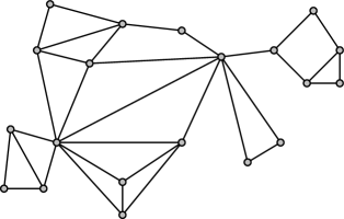
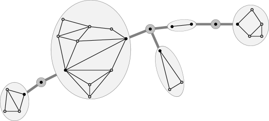
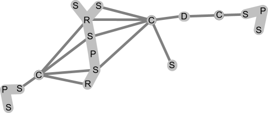
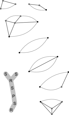
Our approach to edge insertion will use suitable tree-structured decompositions of the given planar graph, according to its connectivity. The concept of these decompositions is also illustrated with an example in Figure 1.
Definition 2.2 (BC-tree)
Let be a connected graph. The BC-tree of is a tree that satisfies the following properties:
-
i)
has two different node types: B- and C-nodes.
-
ii)
For every cut vertex in , contains a unique corresponding C-node.
-
iii)
For every block in , contains a unique corresponding B-node.
-
iv)
No two B-, and no two C-nodes are adjacent. A B-node is adjacent to a C-node iff the corresponding block contains the corresponding cut vertex.
To further decompose the blocks, we consider SPQR-trees for each non-trivial B-node (i.e., whose block contains more than two vertices). This decomposition was first defined in [12], based on prior work of [2, 24]. Even though more complicated than the BC-tree, it requires also only linear size and can be constructed in linear time [22, 16]. We are mainly interested in the property that an SPQR-tree can be used to efficiently represent and enumerate all (potentially exponentially many) plane embeddings of its underlying graph. For conciseness, we call our tree SPR-tree, as we do not require nodes of type Q.
Definition 2.3 (SPR-tree, cf. [5])
Let be a biconnected graph with at least three vertices. The SPR-tree of is the (unique) smallest tree satisfying the following properties:
-
i)
Each node in holds a specific (small) graph where , called a skeleton. Each edge of is either a real edge , or a virtual edge (while still, ).
-
ii)
has three different node types with the following skeleton structures:
-
S:
the skeleton is a cycle (of length or more)—it represents a serial component;
-
P:
the skeleton consists of two vertices and at least three multiple edges between them—it represents a parallel component;
-
R:
the skeleton is a simple triconnected graph on at least four vertices—it is “rigid”.
-
S:
-
iii)
For every edge in we have . These two common vertices, say , form a vertex -cut (a split pair) in . Skeleton contains a specific virtual edge that represents the node and, symmetrically, some specific represents ; both have the ends . These two virtual edges may refer to one another as twins.
-
iv)
The original graph can be obtained by recursively applying the following operation of merging: For an edge , let , be the twin pair of virtual edges as in (iii connecting the same . A merged graph is obtained by gluing the two skeletons together at and removing .
We remark that SPQR-trees have also been used in the aforementioned [11], though with a different approach. We use a slightly modified version of the SPR-tree, which “inserts” a degenerate S-node between each pair of P- or R-nodes:
Definition 2.4 (sSPR-tree)
Let be a biconnected graph with at least three vertices. A serialized SPR-tree (sSPR for short) of is the unique smallest tree satisfying the properties (i)–(iv) of SPR-trees and additionally the following;
-
v)
every edge in has precisely one end being an S-node.
In traditional SPR-trees, S-node skeletons will always contain at least three edges, due to their minimality. Because of property (v), sSPR-trees may, however, now also contain S-nodes representing 2-cycles. In fact, it is trivial to obtain an sSPR-tree from an SPR-tree by subdividing any edge that it not incident to an S-node with such a 2-cycle S-node. We observe that the sSPR-tree retains essentially all properties of SPR-trees, in particular it also has only linear size, can be computed in linear time, and all the previously known insertion algorithms (most importantly the single edge insertion algorithm [18]) can be performed using the sSPR-tree without any modifications.
Given graph:
BC-tree:
Con-tree:

Decomposition graph:
SPR-tree & skeletons
of largest block:
sSPR-tree & skeletons
of largest block:
We are particularly interested in the amalgamated version of the above decompositions, chiefly denoted by con-tree:
Definition 2.5 (Con-tree)
Given a connected, planar graph , let the con-tree be formed of the BC-tree that holds sSPR-trees for all non-trivial blocks of . For technical reasons, if is a trivial -vertex block, we set to be the tree formed by a single dummy node, called a D-node, whose skeleton is .111In a simple graph, a trivial block is always a bridge in . In multigraphs, may also be a set of parallel edges between a vertex pair , whose removal would disconnect . In the latter case, it is trivial that the precise order of the edges is irrelevant, and we could represent via a single edge and its multiplicity instead. Also, let the skeleton of a C-node simply be the corresponding cut vertex.
Clearly, the linear-sized con-tree can be obtained from in linear time.
Furthermore, we will sometimes treat this two-level con-tree as follows:
Definition 2.6 (Flattening a con-tree, decomposition graph)
In the setting of Definition 2.5, let a decomposition graph of be constructed from the union of all the sSPR trees over the blocks of and of all the C-nodes of , as follows:
-
i)
Observe that for each block in holding a cut vertex of , there is one or possibly multiple nodes of whose skeletons contain , and not all of them are P-nodes. Call these nodes of whose skeletons contain the mates of from .
-
ii)
In , for every C-node holding a cut vertex of and for every block of containing , make adjacent to all the mates of from that are not P-nodes.
This “flat” view of a decomposition graph will later be implicitly used, for instance, when defining a con-path (Definition 2.8). The intentional exclusion of P-nodes in (ii) is of technical nature and will be justified later in Claim 2.2.
To summarize, a con-tree (as well as the related decomposition graph) provides us with a natural and easy way to encode all embeddings of a given planar graph. An S-node skeleton has a unique embedding. For an R-node, we can choose between the unique embedding of its skeleton and the mirror image. For a P-node, we can choose an arbitrary cyclic permutation of the skeleton edges. For a C-node, a precise description of the choice is more tricky, but it roughly means we can choose which face of each block (assuming the blocks are already embedded) holds which other block. On the other hand, given a particular plane embedding of a graph , it is trivial to deduce the embeddings of all the skeletons within the con-tree —we shall formalize this observation in Definition 2.9 and Claim 2.4.
2.2 Con-chains and con-paths
In this paper we refer to the optimal single-edge insertion algorithm by Gutwenger et al. [18]. Consider (cf. Definition 1.1 for ) a connected planar graph and let be the vertices we want to connect by a new edge. In a nutshell (see Section 2.5 for details), the algorithm of [18] shows that an optimal plane embedding (of ) for inserting into depends only on the con-tree nodes “between” some node containing and one containing . In this regard, we bring the following specialized definitions.
Definition 2.7 (Con-chain)
Consider a connected planar graph , and its con-tree . Let . The con-chain of the pair in can be uniquely defined as consisting of the following:
-
(i)
the unique shortest path in between a B-node whose block contains and a B-node whose block contains ;
-
(ii)
for each B-node along , two border vertices : for , if let ; otherwise let be the cut vertex in corresponding to the (unique) C-node neighbor of closest to ;222Note that if are consecutive B-nodes on in this order. and
-
(iii)
again for each on , the node sequence of the unique shortest path in connecting nodes of whose skeletons contain the border vertices and in this order.
In iii, uniqueness of the path generally follows from the fact that is a tree. For the possible degenerate case that consists of a single node (whose skeleton holds both ) but is not unique, we choose the “first” such node, according to some arbitrary but fixed order of the decomposition nodes. (In fact, this special case is showcased in Figure 1.)
Definition 2.8 (Con-path)
In the setting of Definition 2.7, a con-path of in is the sequence of decomposition nodes (of type S, P, R, C, and D) resulting from (which contains B- and C-nodes), by replacing each B-node by its corresponding sequence .
Obviously, no con-path may start or end with a C-node. Moreover:
Claim
A con-chain piece (cf. Def. 2.7(iii)) can neither start nor end with a P-node. Therefore, a P-node can occur in a con-path only between two S-nodes, and never at the end nor adjacent to a C-node. ∎
The term con-path is justified by the fact that this node sequence is a path in the decomposition graph from Definition 2.6. We may consider a con-path implicitly oriented, when suitable.
Even though a decomposition graph is not a tree, our con-paths in “behave” similarly as paths do in a tree:
Claim
Consider two con-paths , of pairs and in the decomposition graph of a graph . Then , if non-empty, forms a consecutive subsequence in each of .
Proof
In this proof we view as paths in the graph . Assuming a contradiction, there exist distinct subpaths , , such that share common ends but are internally disjoint otherwise. Since C-nodes are cut nodes in by Definition 2.6, contains no C-nodes except possibly and/or . If neither of is a C-node, then are contained in the same sSPR-tree of and so , a contradiction. Similarly, if both are C-nodes then by uniqueness claimed in Definition 2.7.iii, it is .
It remains to consider that, up to symmetry, is a C-node and belongs to an sSPR-tree where is a block incident with , the cut vertex of . Let be the neighbor of on , . Then lies on the unique - path in , and since both the skeletons contain , it is . Unless is a P-node, is thus formed by a single edge . In the case of being a P-node, cf. Claim 2.2, is not an end of either . Therefore, if is the (other) neighbor of on , , we have and by minimality in Definition 2.7.iii it is , a contradiction again. ∎
2.3 Towards “embedding preferences”
On a high level, the starting point of our algorithm is to solve the single edge insertion problem for each edge into independently. In this way we obtain so called embedding preferences (Definition 2.11) for each node . Equipped with all these preferences for all edges of , we have to decide on an embedding of which, essentially, “honors” as many of these preferences as possible. It should be understood that the preferences for distinct edges of may naturally conflict with one another. We will ensure that we pick an embedding which guarantees that any can be inserted into (as a new edge ) without “too many” additional crossings, compared to its individual optimum .
The exact scheme for our embedding preferences is a critical part of the proof of our algorithm, and in order to explain our complete definitions (Section 2.4), it seems worthwhile to discuss the situation and drawbacks of possible alternatives beforehand. We start with a summary of the algorithm [18] to optimally insert a single edge. Our description is very informal since we never use the details of this algorithm in our paper, but the summary will help us to explain the (somehow unexpected) deep technical problems connected with our extension to multiple edges.
Single edge insertion algorithm [18].
We can interpret the algorithmic steps of [18] for as what we call simple embedding preferences. In our terminology of Definition 2.7, the insertion algorithm for the edge first considers individually each B-node of . Let be ordered such that contains and contains . For , one independently computes an embedding and a local insertion path as follows.
The source (target) of the local insertion path is either the vertex (), if (), or otherwise () in —the virtual edge(s) corresponding to the predecessor and the successor of , respectively. The insertion path is computed in the dual of the skeleton : For S-nodes, the path is simply one of the two faces, and no crossings arise. Similarly, no crossings arise for P-nodes; one chooses a skeleton embedding in which the source and the target lie on a common face. This face then constitutes the insertion path. In case of an R-node, the embedding of is fixed and one chooses any shortest path in its dual as the insertion path. Crossins may, unavoidably, arise in this case.
In each of the cases, if the source or the target is a virtual edge, one also notes whether the insertion path attaches to it from the left or the right side (left/right with respect to an arbitrarily fixed but consistent direction of all the virtual edges). This solution and note together constitute the simple embedding preference for each node of in the con-tree of .
All the simple embedding preferences along can be simultaneously satisfied, by stepwise “gluing together” the individual subembeddings along twin pairs of virtual edges: this is trivial when the local insertion paths of adjacent nodes attach to the twin pair from different sides, and one flips the next skeleton embedding before gluing in the other case. For other nodes without preferences, one picks any embedding, as the insertion solution is independent of this decision.
Having embedded the blocks of , it is now easy to deal with C-nodes. For any C-node of (corresponding to a cut vertex ), let be the incident blocks. The corresponding “loose ends” of the previously computed insertion paths in and attach to from certain faces of embedded , respectively. In an embedding of the union one identifies with , such that the insertion paths are joined together without additional crossings. All remaining blocks can be joined arbitrarily as the insertion solution is independent of these decisions.
Properties of good preference schemes.
In our case of multiple edges, the above description has inherent problems, some rather obvious, some more subtle. First, simple prefereces require a stepwise resolution (i.e., having to decide all the blocks, before being able to properly define C-node preferences), which does not allow for an easy way of combining multiple insertion paths.
Second, simple preferences are capable of handling only a quite restricted class of embeddings. In our case, this would inevitably lead to a situation in which two distinct insertion paths set different preferences for the nodes they follow together, even though there exists an equally optimal solution for one of the paths that nearly matches the preferences of the other path. A very simple example of this is when the first path decides for an embedding while the second one decides for the mirror image of . Note, however, that there is no big problem with routing through rigid skeletons of R-nodes, as one can always define a unique canonical order on all the dual paths there, and a unique default choice between the skeleton and its mirror image (flip).
The aforemention problem gets tougher when considering S- and P-nodes (and also C-nodes in greater generality). Consider that an embedding of a P-node skeleton is specified by a clockwise order of its edges (yes, it is actually enough to specify a pair of consecutive edges). However, another specification at may reverse the edge order of the skeleton and simultaneously flip both the adjacent skeleton embeddings. This results in, essentially, the same embedding of , and has to be captured as “the same” by our new preference scheme. But then we would mix the concepts of specifying subembeddings (e.g., the edge order at P-nodes) and of handling the gluing operation (flips). In this perspective, our extension from SPR- to sSPR-trees can be seen as a first step to decouple flipping decisions from ordering decisions within P-nodes—it allows us to encode, at a mandatory S-node, whether the adjacent skeletons are flipped “the same way” or “the other way”; with special labels nonswitching/switching.
Though, the problems are not over yet. One would also, naturally, like to define the preferences so that it is trivial to validate if some given embedding satisfies the preferences or not. In other words, one would like that every bit of information stored as a preference has a directly observable counterpart in the final embedding . While there are ways to rigorously define a suitable preference scheme achieving this goal,333For example, it is the preference scheme originally described in the conference version of this research [8]. the solution is not satisfactory for the following reason. With any directly observable preference scheme, it seems inevitable that validation of the embedding preference of one node requires us to look at the embedding preferences of some of its neighbors (sometimes up to distance two). Not surprisingly, this would bring big complications for the proofs, resulting in long (and difficult to verify) case-checking arguments.
In our new preference scheme, we hence trade the (part of) direct observability property for a new property of strong locality—demanding that validation of the embedding preference of one node is possible without looking at the preferences of any other nodes. For this purpose we shall introduce a new kind of “unobservable” information into an embedding—a so called spin (of virtual edges), which helps to achieve the goal of strong locality by providing us with kind of a “communication channel” between neighboring preferences. All of this is the subject of the following rather technical Section 2.4.
2.4 Embedding preferences in a Con-tree
In this section we give the formal definitions establishing our scheme of embedding preferences for con-chains that achieves the goal of strong locality, as informally explained in Section 2.3.
We start with formally specifying what an embedding is (Definition 2.9) and what the partially unobservable information we add to it is (Definition 2.10 and Claim 2.4). Then, we define the exact pieces of information we are going to store at a con-chain node as its embedding preference (Definition 2.11), and we couple this definition with a specification (respecting strong locality) of what it means that a certain collection of embedding preferences is honored by an embedding of (Definition 2.12).
For reference in the following definitions, we need to define certain “defaults” for embeddings of a graph . Let be an arbitrary but fixed embedding of in the plane (i.e., including the specification of the unbounded face). From we derive (a) the default embedding for each R-node skeleton (distinguishable from its mirror), and (b) the default face for each S-node skeleton (distinguishable from its other face) by picking the bounded face of this skeleton in . Note that the default face is well-defined even for an S-node skeleton forming a -cycle since the skeleton edges are labeled. Specially, for each D-node skeleton (a bunch of parallel non-virtual edges), we observe that it is always possible to draw all its edges close together such that the rest of is embedded in one face of it and that no crossings with the inserted edges arise. This chosen face, in any embedding of , will be called the default face of a D-node skeleton (while disregarding the names and order of the skeleton edges).
Definition 2.9 (Embedding specification)
Consider a connected planar graph , an embedding of , and the con-tree . Let an embedding specification be a collection of information specified as follows:
-
i)
For each R-node of , we specify one of the labels flipped or nonflipped; the information is nonflipped exactly when the embedding of induced by is the default one.
-
ii)
For each P-node of , we specify (an arbitrary) one of the two vertices of and the cyclic clockwise order of the edges of around it in the embedding of induced by .
-
iii)
For each C-node of and each pair of incident blocks, we specify the face of that contains in the embedding , for .
An embedding uniquely determines the embedding specification by definition. Conversely, it immediately follows that:
Claim
If are two embeddings of a connected planar graph such that , then and are equivalent (and also not mirrored images of each other). ∎
While this embedding specification of Definition 2.9 cannot be used directly as a basis for our embedding preference scheme, it serves as a blue print of what our preferences need to model.
Recall our discussion from Section 2.3 about flipping skeleton embeddings during the gluing operation of adjacent skeletons. For the intended purpose of decoupling the flipping decision of a glue operation of Definition 2.3 from the embedding decision for skeletons, we introduce the concept of spins in an embedding. Interestingly, in general, spin values are not fully determined by a particular embedding. A spin can also be (informally) seen as a 1-bit communication channel transferring certain information between nonadjacent con-tree nodes, which will allow us to establish the desired strong locality of embedding preferences.
Definition 2.10 (Enriched embedding, spins)
Consider a connected planar graph , its embedding and the con-tree . A CS-pair is a tuple where is a cut vertex in and is an S-node of whose skeleton contains . In an enriched embedding of , we charge each virtual edge and each CS-pair of the con-tree with either a positive or a negative spin, subject to the following properties:
-
-
(E1)
A virtual edge and its twin will always be charged identically.
-
(E2)
For an R-node , if the embedding of the skeleton is the default one (i.e., is labeled nonflipped in ), then all the virtual edges in are charged with a positive spin; otherwise, all those virtual edges are charged with a negative spin.
-
(E1)
The role of CS-pairs deserves a further informal explanation. First, note that in such a pair is a mate of in the sense of Definition 2.6. Second, a CS-pair will be used conceptually similarly to a pair of twin virtual edges of an sSPR tree—while twin pairs of virtual edges are used to glue pieces of an sSPR tree together, CS-pairs will be used to specify the precise way two adjacent blocks are glued together at a cut vertex. Though, we will need this additional information only in the case when is an S-node (and not for R-nodes for which we may explicitly refer to a certain face).
Since R-nodes are never directly adjacent, there cannot arise any conflicting spin values from Definition 2.10. Most importantly, all spin values not predeterminded by properties E1 and E2 are only loosely correlated with the embedding , and they will not be part of the embedding preference. Their role is to function as a mediator between our embedding preferences and an actual embedding. In other words, we will only ask whether there exist spin values such that an embedding satisfies our preferences, and not what the spin values are.
The following two entangled definitions achieve all our goals concerning embedding preferences in a con-tree and their interpretation.
Definition 2.11 (Node embedding preferences for a con-chain)
Consider a connected planar graph , its con-tree , and the decomposition graph (Definition 2.6). An embedding preference of a node is defined (only) if is an S-, P-, or C-node. One piece of information that stores is a pair of distinct nodes , called the -peers of , such that are neighbors of in . Furthermore:
-
-
(P1)
If is a P-node, we only store these peers (which, in this case, are S-nodes by definition) in .
-
(P2)
If is an S-node, we additionally store in one of the labels switching or nonswitching. However, if neither nor is an R-node, the stored label must always be nonswitching.
-
(P3)
If is an C-node, then the stored -peers are R-, D- or S-nodes by definition. For , if the peer is an R-node, then we additionally store in a label specifying a face in the skeleton .
-
(P1)
Consider a non-adjacent vertex pair and its con-chain in . Let be the corresponding con-path. An embedding preference of (equivalently, a preference of ) is a collection of embedding preferences over those internal nodes of that are neither R- nor D-nodes, subject to the following restriction:
-
-
(P4)
For every individual preference in , the two -peers of must be the two neighbors of on .
-
(P4)
For consistency, we say that a node whose embedding preference is not defined in Definition 2.11 ( might be an R- or D-node), has a void embedding preference. Then, we can rigorously speak about embedding preferences of all the internal nodes of a con-path , or of all nodes in an arbitrary subset of .
Definition 2.12 (Honoring an embedding preference)
Consider a connected planar graph and any embedding of , specified via its embedding specification . Let be a subset of nodes of and be a collection of (arbitrary) node embedding preferences over . We say that honors the embedding preferences if there exists an enriched embedding of such that, for every where is non-void, is good for . That is, is good for (where falls into one of the cases (P1)–(P3) of Definition 2.11) if the appropriate one of the following cases holds:
- case 1:
-
is a P-node. Let be the -peers (both being S-nodes) of , and let , denote the virtual edges in corresponding to , , respectively. The cyclic order of the edges in specified in is such that and occur as neighbors—they form a common face in . Moreover, for each , the face corresponds to the default face of if has the positive spin in , and corresponds to the other face of if the spin is negative.
- case 2:
-
is an S-node. There are two spin values associated with via : for , the -th spin value is the one charged to the virtual edge if the -peer is an R- or P-node, and otherwise the -th spin value is the one charged to the CS-pair formed by and the cut vertex of the C-node . If the label in is switching then exactly one of these spin values of is positive and the other one negative, while if the label is nonswitching then both these spin values have to be the same.444Note that (some of) the spin values in are correlated with the specification according to Definition 2.10, and so is implicitly considered in the case 2, too.
- case 3:
-
is a C-node. Let be the blocks the -peers of belong to, and let be the cut vertex corresponding to . There are two skeleton faces, of and of , associated with via as follows. Let . If is an R-node then is explicitly given as a label in . If is a D-node then is the default face of . If is an S-node, then is the default face of in the case that the CS-pair is charged with a positive spin, and otherwise (negative spin) is the other face of . The two faces specified in for at must correspond to and (disregarding their orientation), respectively.
Void embedding preferences from , and possible preferences of other nodes not in , do not matter when deciding whether an embedding honors as above. We also call any enriched embedding of that satisfies all the requirements of Definition 2.12 a good enriched embedding for .
Claim
Assume that a plane embedding of honors embedding preferences of a con-chain . Then, the spin values charged to the virtual edges and the CS-pairs along are consistent over all possible good enriched embeddings for . These spin values can be derived directly from the embedding specification (w.r.t. the implicit default embedding of ).
Proof
Since honors , there exists at least one feasible spin assignment by definition. We are going to show that the spin values are uniquely determined along the con-path .
Consider any edge . If one of is an R-node (and the other one is not a C-node), then the two virtual edges associated with in are charged a spin value that is uniquely determined by Definition 2.10.
Assume that, say, is a C-node of a cut vertex . Then a spin is charged to the CS-pair only if is an S-node. We determine the spin value of by comparing the face specified in for and the block of with the default face of , as claimed in Definition 2.12, case 3.
The remaining case to consider is, up to symmetry, that is a P-node and an S-node. The spin value of the twin virtual edges (in , respectively) is again determined by comparing the embedding of the P-skeleton in (precisely, its face specified by the preference ) to the default face of , as claimed in Definition 2.12, case 1. ∎
The consequence of the above claim is very interesting. On the one hand, it tells us that, effectively, we do not need to care too much about enriched embeddings from now on, except for in “low-level” proofs. On the other hand, however, it is not straightforwardly possible to remove the spins from the definition of embedding preferences altogether. A key problem occurs with an S-node and its virtual edge such that an embedding preference of the neighbor does not refer to (but to other nodes): then, the spin value of is undetermined and represents a “communication channel” between the embedding preferences of adjacent nodes. Abandoning this vital “communication link” would require us, e.g., for a P- or C-node in Definition 2.12, to refer also to the embedding preferences of the neighbors and thus would violate our goal of strong locality (with some nasty consequences in the later proofs).
2.5 Single edge insertion and embedding preferences
Note that it is not a priori clear, given the additional conditions in Definitions 2.11, 2.12 and the elusive nature of spins, that our treatment of embedding preferences is capable of rigorously describing every optimal solution to the single edge insertion problem. It is the task of coming Lemma 1 to prove this important and nontrivial finding. (While perhaps looking similar to Claim 2.4, this task is in fact very different from the former one.)
Lemma 1
Let be a connected planar graph and . Assume that is a plane embedding of such that a new edge can be drawn into with crossings. Then there exists an embedding preference of the con-chain such that honors .
Proof
Let be the corresponding con-path, and be the embedding specification of . There are two tasks in this proof:
-
a)
to deduce individual embedding preferences (forming ) for all internal nodes of , and
-
b)
to specify an enriched embedding such that all the conditions of Definition 2.12 are satisfied for via .
As for a), we easily determine all information except the switching attributes of the internal S-nodes on from Definitions 2.11, 2.12: the -peers are the neighbors of on and, in the case of a C-node with an R-neighbor, the face label(s) follows Definition 2.12, case 3.
Assuming for a moment that, for each internal P-node of , the two virtual edges of the -peers form a face in , in b) we can determine spin values along exactly as in the proof of Claim 2.4. Remaining spin values can be charged arbitrarily, giving an enriched embedding of . Returning back to a), the switching attribute of each where is an S-node now follows from charged spin values and Definition 2.12, case 2.
It remains to verify three facts; our assumption about P-nodes of , and fulfillment of Definition 2.11 2 and of Definition 2.12. This can be done conveniently along the cases of the latter definition. Let be an internal node of and be the two -peers of (its neighbors on ).
- case 1:
-
is a P-node. For , let be the subgraph obtained by recursively gluing skeletons to the virtual edges of except to . Up to symmetry between the indices , either or is separated from by a cut vertex of such that . Notice that is a split pair in formed by . Obviously, the edge in optimal does not cross any component represented by a virtual edge of , other than possibly . Therefore, the virtual edges indeed form a face in the embedding specification of .
- case 2:
-
is an S-node. The switching label of has already been chosen to satisfy Definition 2.12 via . As in the previous case, the edge in optimal obviously does not cross any of the components represented by the virtual edges of other than possibly . Hence, unless one of is an R-node (in which case or has been charged a spin by Definition 2.10), both the spin values charged for and (each may be of a virtual edge or of a CS-pair ) refer to the same face of and the label of is nonswitching, in agreement with Definition 2.11.
- case 3:
-
is a C-node. In this case there is nothing more to discuss since and have already been chosen to satisfy Definition 2.12. ∎
In the algorithmic context, the key is to find such an embedding preference as in Lemma 1 efficiently. Using Lemma 1, we translate the main result of [18] into our slightly different setting as follows:
Theorem 2.13 (Gutwenger et al. [18], reformulated)
Let be a connected planar graph and . Let be the con-chain of the pair in . We can find, in linear time, an embedding preference of such that we require exactly crossings to draw a new edge into any plane embedding of that honors .
Any embedding preference with the properties as described in Theorem 2.13 will be called an optimal embedding preference of (the con-chain of) the pair in . Note that such an optimal preference is not necessarily unique and, furthermore, that optimality of inserting does not depend on embedding specifications/preferences at the con-tree nodes other than the internal nodes of .
3 MEI Approximation Algorithm
We now finally have all the technical ingredients to discuss our new approximation algorithm for the problem (Definition 1.1). The overall idea of the approximation is to suitably combine the individually computed optimal embedding preferences over all the edges of , and to prove that not too many conflicts arise, leading to only few additional crossings as compared to the sum of the individual optimal solutions. The aforementioned strong locality, achieved in Definition 2.12, will be crucial for the algorithm.
3.1 Coherence, and repairing insertion paths
Before jumping into a solution of the MEI problem, we have to analyze the kind of conflicts that arise between optimal embedding preferences of two distinct pairs and from . Intuitively, if the con-chains of and locally traverse the con-tree of in the same way, then both of them should have “the same” optimal individual embedding preferences there.
Though, the formal finding is not as straightforward as the previous claim due to two small complications; first, the situation of R-nodes is more delicate (cf. Definition 3.1), and second, an optimal embedding preference of a pair is not necessarily unique and this has to be taken into an account (cf. Lemma 2). Recall that our con-paths can be viewed as paths in the decomposition graph, and this will be our default view in this section.
Definition 3.1 (Coherence in con-paths)
Consider two con-paths in the decomposition graph of a connected planar graph , and their non-empty intersection (which is a subpath by Claim 2.2). We say that are coherent at if is an inner node of and the following holds: if are the two neighbors of on and , , is an R-node, then also is an inner node of .
We would like to add a small remark on the situation in which is, simultaneously, an end of and an end of both . Assume the insertion edges defining end in a common vertex of the skeleton of . Then, we could also define the con-paths to be “coherent” at . However, we refrain from doing so as it would cause unnecessary complications in the proofs.
Lemma 2
Let be a connected planar graph, the con-tree of , and . Consider any optimal embedding preferences and of and , respectively. Construct alternative embedding preferences of as follows: use the embedding preferences of for all nodes at which are coherent, and those of for all other nodes of . Then, is again optimal for .
Proof
Let and be the considered con-paths. We iteratively change to . We consider the nodes at which are coherent one by one, and claim by induction that at each step (the order of which is unimportant) the current embedding preference is optimal for . The claim is trivial if holds the void preference anyhow.
Let be the two neighbors of on . Assume that is a P-node. By Definition 2.11, the embedding preferences of and at are the same, since are the same neighbors of on both paths . Hence, nothing changes at this step. By the same argument the preference at remains unchanged when is a C- or S-node, unless one or both of is an R-node.
It remains to consider the case that is a C- or S-node and is an R-node for some . Let be the neighbor of other than on (since is not an end by Definition 3.1). Let be the element of the skeleton corresponding to and the element of corresponding to ( is a cut vertex if is a C-node, but a virtual edge if is an S-node; analogously for ). An optimal solution to the single edge insertion of requires to find a shortest weighted dual path locally in the rigid skeleton from some face incident with to a face incident with . This local setting is the same for as for , and so the same dual path from to within can be taken also in an optimal solution to the insertion of .
So, we get that the embedding preference of at a C-node (which lists some face of incident with cut vertex ) can be changed in to that of at (which lists as the face incident with ) while preserving optimality. This is simultaneously done for if both are R-nodes. Similarly for an S-node ; a choice of one of the two faces of incident with virtual edge determines the spin of , which consequently shows that the switching attribute of at can be changed to that of at while preserving optimality. ∎
Remark 1
Algorithmically, it is trivial to ensure that multiple calls to the same dual shortest-path subproblem within an R-node skeleton always give the same solution. This can, e.g., be achieved picking the start vertex for the search from in a deterministic fashion (e.g., based on some arbitrary indexing), and using a deterministic algorithm for the dual path search. Using this method and with respect to Lemma 2, one can easily ensure that all the optimal embedding preferences computed individually by Theorem 2.13 already agree at any coherent nodes.
Since we deal with multiple edge insertion in our paper, we have to handle situations when not all the optimal embedding preferences of the pairs from can simultaneously be satisfied in any plane embedding of . We use the following terminology.
Definition 3.2
Let be embedding preferences of any set of con-tree nodes. We say that an embedding honors the preferences with defect if there exists a subset of size such that honors (Definition 2.12) the restriction .
Lemma 3
Let be a connected planar graph, , and optimal embedding preferences of . Assume that is an embedding of such that honors with defect . Then it is possible to draw a new edge into with at most crossings.
Before we prove this lemma, we may informally describe its statement as follows: For every individual preference on the con-chain of that is not honored by in the sense of Definition 3.2, we can apply one “repair operation” to costing at most new crossings (over the optimal insertion).
The following is needed in the proof:
Claim
Let be the con-path of a pair . Consider an internal P-, C-, or S-node , and let be a vertex of the skeleton .
(a) .
(b) Let be optimal embedding preferences of and be their restriction to the internal nodes of of the pair . Then, is an optimal embedding preference of .
Proof
Part (a) follows from the fact that there is a vertex cut in with , separating from : if is a C-node (of the cut vertex ) then ; otherwise, there is a suitable 2-cut in the skeleton —the latter is a cycle or a parallel bunch. Hence, in any plane embedding of , the edge has to be drawn through a face incident with , and the edges can be drawn along the arc of up to this face , giving an upper bound on . Specially, for that minimizes we get .
We prove (b) by means of contradiction. Assume is drawn optimally (with crossings) into a suitable plane embedding of , and let and be drawn in as in the previous paragraph with and crossings each. Then due to (a) and optimality. If restricted to was not optimal, then would be achieved by some embedding of . But then, there is a suitable edge order and/or flipping decision at to combine and across the cut (from the previous paragraph) such that inserting requires no crossings at and consequently only crossings altogether—a contradiction. ∎
Proof (of Lemma 3)
Let be the con-path (in the decomposition graph of ) of the pair . We prove the lemma by induction on . The base case is already established by Theorem 2.13.
We choose the first node on from the -end such that at is not honored by . Then is an internal P-, C-, or S-node of . Let be any vertex of the skeleton , and be the con-paths of and , respectively. Note that , and that—by Claim 3.1(b) and symmetry—the corresponding restrictions arising from are optimal embedding preferences of and , respectively.
Consequently, honors as whole (i.e. with defect ) and with defect . So can be drawn into with crossings by Claim 3.1(b) and can be drawn into with at most crossings by the induction assumption. Altogether, using Claim 3.1(a), is drawn with at most crossings, each one occuring on either or . Consider the arc arising from joining the edge arcs representing and . We would like to use to draw but passes through the vertex (where meet). By a tiny perturbation of in a small neighborhood of in we can obtain a proper drawing of at a cost of at most additional crossings with (at most half of the) edges incident to . This establishes ∎
3.2 The approximation algorithm
Algorithm 3.3 (Solving MEI with additive approximation guarantee)
Consider an instance of the multiple edge insertion problem : given is a connected planar graph and a set of pairs of vertices of such that .
-
(1)
Build the con-tree .
- (2)
-
(3)
Denote by the set of indices of all the pairs from that have a preference (possibly void) at a con-tree node . For each of , choose (suitably) a subset according to some rules defined later on, see Remark 3 for details.
-
(4)
For , let denote the individual preference (if existent) of at . Let be the multiset of the individual preferences at requested by (only) those relevant con-paths that have been selected in step 3.
-
a)
For each node of , if then set a resulting preference arbitrarily or void. Otherwise, choose a preference such that is among the elements with maximum multiplicity in (a semi-majority choice).
-
b)
Using Lemma 4 (see below), compute a plane embedding of that honors the embedding preferences .
-
a)
-
(5)
Independently for each , compute (deterministically; see Remark 5) the insertion path for into the fixed embedding .
We defer a detailed runtime analysis of this algorithm to the end of the section. First, we would like to comment on some of the steps in this algorithm:
Remark 2 (Step 2 of Algorithm 3.3)
Based on Remark 1, we can assume that our algorithm produces consistent embedding preferences at coherent nodes (for any pair of con-paths) without further treatment. If, for any reason, one does not want to honor Remark 1, there is a simple algorithmic workaround. For ; for any and any node of such that are coherent at , change the individual preference of at to that of at . By Lemma 2, the final so-modified embedding preferences (still denoted by ) are still optimal for their respective pairs .
Remark 3 (Step 3 of Algorithm 3.3)
The practical meaning of step 3 is that we may choose to “ignore” some (or even all) of the individual preferences requested by (some of) the con-paths. Herein, we will closely discuss two variants. We may choose
-
•
arbitrarily, as long as if ; or
-
•
specifically, to fulfill upcoming Definition 3.4.
Although in particular the first variant may sound silly, there are actually two good reasons for allowing freedom in the choice of . First, this leaves plenty of room for (heuristic) algorithm engineering in practical applications, while still providing a firm approximation guarantee for essentially any somewhat reasonable choice of (the first variant, Proposition 1). Observe that the first variant also covers the possibility of simply setting for all , and also the perhaps most naïve choice, picking one arbitrary and setting . Second, for a carefully crafted (and still efficient) choice of we can in fact provide a stronger worst-case guarantee (the second variant, Theorem 3.5) than if we considered all the preferences together.
Remark 4 (Step 44a of Algorithm 3.3)
We do not perform any further optimization of the choice of in the algorithm here, even though it can be possible that some embedding specification could be simultaneously good for several distinct individual preferences at (again, this leaves room for further possibly heuristic algorithm engineering). The presented semi-majority choice is just right to prove the algorithm’s overall approximation ratio.
Remark 5 (Step 5 of Algorithm 3.3)
By using a deterministic shortest path algorithm in the dual of , we can trivially ensure that distinct insertion paths do not cross multiple times. If, for some reason, we do not apply a sufficiently deterministic algorithm, we can simply exchange subpaths as a postprocessing step, such that in the end all inserted edges cross each other at most once.
While deferring the lengthy implementation details of step 4 to Lemma 4, we illustrate the underlying idea of Algorithm 3.3 with the following simple claim and its corollary in Proposition 1.
Claim
Consider the setting of Algorithm 3.3. For any , there are at most two nodes of such that both exist and , i.e., the computed optimal preferences and request different individual preferences at .
Proof
Since individual embedding preferences are stored at the corresponding con-path nodes, conflicting preferences may only arise on , which is a path by Claim 2.2. We know that agree at all coherent nodes in (either due to the deterministic algorithm or after applying Lemma 2). By Definition 3.1 of coherence, possible conflicts could only be at (a) the ends of and (b) nodes neighboring an R-node that is an end of . Recall that R-nodes store the void embedding preference, and so at each end of there can only be one troublesome node, either of type (a) or (b). This establishes the claim.∎
Proposition 1 (Weak estimate)
Note that already this short statement establishes the approximation factor given for the MEI problem in the conference version of this paper [8]; herein (Theorem 3.5) we will later establish a stronger bound as well.
Proof
We want to show, in the language of Definition 3.2, that the sum of defects of honoring each one of the optimal preferences , , from the algorithm is at most . Inequality (6) would then immediately follow from Lemma 3 and the fact that the edges of pairwise cross at most once.
Assume the notation of Algorithm 3.3. Let be a good enriched embedding for . We say a pair , for any and , forms a dirty pass if is not good for (Definition 2.12). Obviously, the total number of dirty passes equals the sum of defects of . We show that all the dirty passes of can be counted towards unordered index pairs such that each such pair is “responsible” for at most two dirty passes altogether. Indeed, if is a dirty pass, then there exists some such that the computed preference at is . We hence count towards and, by Claim 3.2, we already know that this may happen at most twice for each pair . ∎
Finally, we provide a straightforward implementation and a proof of correctness of step 44b in Algorithm 3.3.
Lemma 4
Let be a connected planar graph and a con-tree of . Assume is an arbitrary collection of node embedding preferences for . Then there is a plane embedding of such that honors the preference . The embedding can be computed in linear time.
Proof
In the first step we fix a plane embedding of each block of . If is trivial, its embedding is already pre-specified (or even unique). Otherwise is determined by deducing an embedding together with all the spin values.
Let be a subtree of the sSPR-tree of stored in . We prove by induction on that there exists a good enriched embedding of for restricted to (the nodes of) . The claim holds for empty . Let be a leaf of , and let be a good enriched embedding of for restricted to . Consider the type of as in Definition 2.3:
-
a)
If is an S-node, then and we only determine the associated spin values. Let be the -peers stored at , and the respective virtual edges in . Actually, if , , is a C-node, we simply refer as to the corresponding CS-pair. Up to symmetry, . If as well, we set the spin of arbitrarily (while otherwise it has already been set by ). In any case, we select the spin of to honor the switching/nonswitching label at , and we charge the remaining spins associated with arbitrarily.
-
b)
If is an R-node, it may be that its neighbor in is an S-node such that is one of the -peers of . If this is the case, then we get by flipping the embedding of in such that the spin value and switching label specified by are honored. Otherwise, let . We also set the spin values of the virtual edges in accordingly.
-
c)
If is a P-node, then the -peers are S-nodes where, up to symmetry, . We arbitrarily set the spin values of all the virtual edges of , except possibly if (then the spin has been set by ). For we choose an embedding of , and a spin value of , such that form a face as required per Definition 2.12, case 1.
Now, we have an enriched embedding of with the property that, for each block of , induces an enriched subembedding that is good for restricted to . To obtain the final embedding of , it remains to modify —only at the cut vertices of —such that resulting is good for at all the C-nodes of . Note that, technically working with spherical embeddings, we can freely choose the outer face of any in the plane without changing the embedding specification at any node of .
We again proceed by induction on the size of a suitable subtree such that there exists an embedding of good for restricted to all the C-nodes and all the sSPR-trees of . For technical reasons, needs to be special, meaning that all the leaves of are B-nodes (which clearly holds true for whole ). The base of the induction is formed by a singleton B-node of a block , for which the subembedding has been fixed above.
In the induction, any arising will contain a C-node , such that if results by removing and all its adjacent B-leaves, then is empty or again a special tree. By the induction assumption, let be an embedding of that is good for restricted to . Let be the cut vertex represented by , and be the -peers at where belongs to the adjacent sSPR-tree , .
For , we take a specific face of the skeleton : for a D-node , we take its default face; for an R-node, is specified by the label in ; for an S-node, is determined by the spin value of the CS-pair . Let be the corresponding face of the (sub)embedded block . We may assume, up to symmetry, that does not belong to an sSPR-tree held by . We make the outer face of , and we construct from by rearranging the embedding specification at (and, thereby, the blocks incident with ) such that occurs inside the face . It is clear that is now good also for .
Finally, following the constructive steps of this proof, it is routine to verify that the resulting embedding can be computed in overall linear time. ∎
3.3 Improved approximation guarantee
We are going to turn the weak approximation guarantee of Proposition 1 into an asymptotically optimal one—with the additive term improved down to . To achieve this goal, we will count the dirty passes of , and so the overall defect, similarly to the proof of Proposition 1, but with respect to a special order of the con-paths such that, at each step, we account for roughly at most new ones. The two crucial ingredients for this approach are the semi-majority choice of the preferences in Algorithm 3.3 and the following folklore555This claim is better known in the following formulation: The intersection graph of subtrees in a tree is chordal and it contains a so-called simplicial vertex. claim.
Claim
Let be a tree, and , , be an arbitrary collection of subtrees of . Then there exists and such that, for every , if intersects then .
Proof
Consider any graph , subgraph , and . Let the distance from to be the minimum distance between and a vertex of , and the shore of from be the subset of those vertices of having distance from . Clearly, if is a tree and is connected, then the shore of must always be a single vertex and every path from to contains .
Choose any vertex and let be the maximum distance from to any , . If then fulfills the claim for any . Suppose and let some , , with the shore , be at distance from . We show that this choice of fulfills the claim. Consider any , , that intersects . Clearly its distance from is at most . Let and let be the shore of from . According to the previous paragraph, the path from to must contain both of , and so , too. ∎
We first briefly outline how Claim 3.3 can help to improve the estimate for Algorithm 3.3 over Proposition 1:
-
a)
For an instance , assume that the decomposition graph is a tree (this happens, e.g., when is -connected). Let , , be the con-paths of the insertion pairs . Then, by Claim 3.3, there is such that all of the con-paths hitting do so in the same node .
-
b)
Let be the two half-paths of from a starting in , and let be the total number of con-paths sharing with . We can claim that the embedding computed in Algorithm 3.3 honors the preferences restricted to with defect at most : informally, by our semi-majority choice, the embedding might not be good only for individual preferences of at those nodes of where at least half of all participating con-paths “divert from” (at this node or at the next R-node). An upper bound for each of hence follows easily, and we may account for in the defect sum due to itself.
-
c)
If the previous bound was extendable recursively to all the con-paths, a final estimate for the sum of all the defects would be at most (while the actual bound in Theorem 3.5 will come out just slightly worse).
For an informal reference, we will call this approach a -defect argument. There are, however, two big problems with the outlined (optimistic) scenario:
Remark 6 (On utilizing the -defect argument)
-
a)
Since does not have to be a tree, Claim 3.3 does not directly hold for it (however, we at least know that two con-paths may only intersect in a subpath in ).
-
b)
A somehow less obvious problem with the -defect argument pops up when applying it recursively—after removing several of the con-paths, it is no longer true that a semi-majority choice in this subcollection is the same as the semi-majority choice made by the algorithm (for all the con-paths).
To address Remark 6 a, we refine Claim 3.3 in following Lemma 5. Note, however, that if the given graph would be biconnected, would be a tree and we could directly use Claim 3.3 and its consequent bound instead. Consider a con-path and an internal node . Recall the notion of a mate from Definition 2.6, and the fact that a mate of a cut vertex may also be a P-node in which case it is not directly adjacent to ’s C-node in . We say that a node is a substitute for w.r.t. if (cf. Figure 2):
-
•
is a C-node of a cut vertex of such that is a mate of (and so is not a C-node), and
-
•
there is a neighbor of on such that or is a mate of , too.
In the following lemma, we consider some index set . While it is most natural to think of as , we will later apply this lemma also for subsets of the latter.
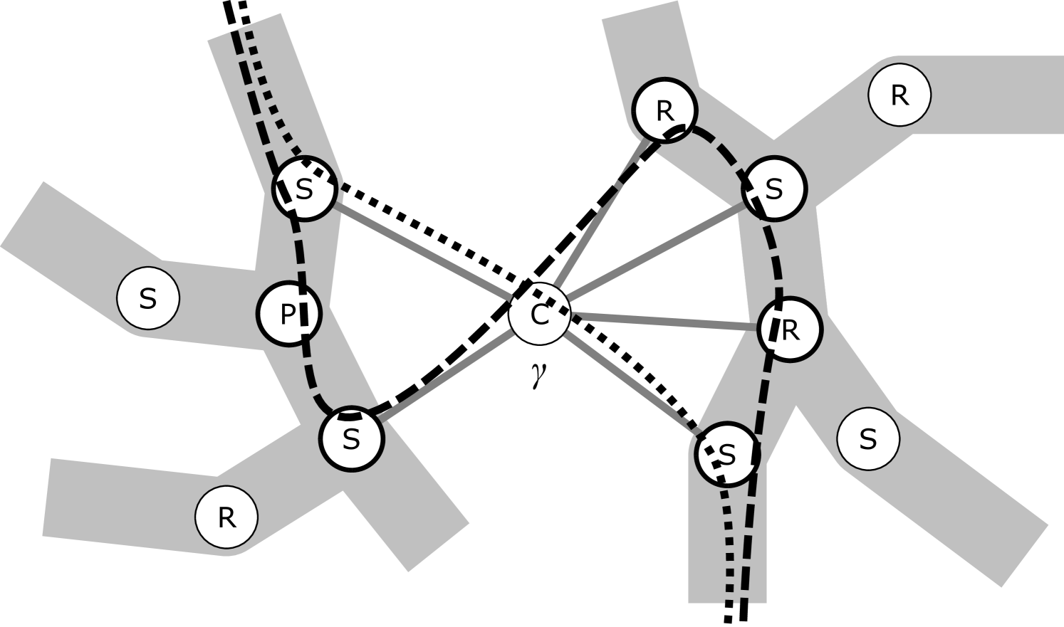
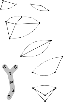
(a) We could reroute the dotted con-path to become the dashed con-path, without problems. We require no embedding preferences at the newly added nodes, as their skeletons all share the cut vertex represented by .
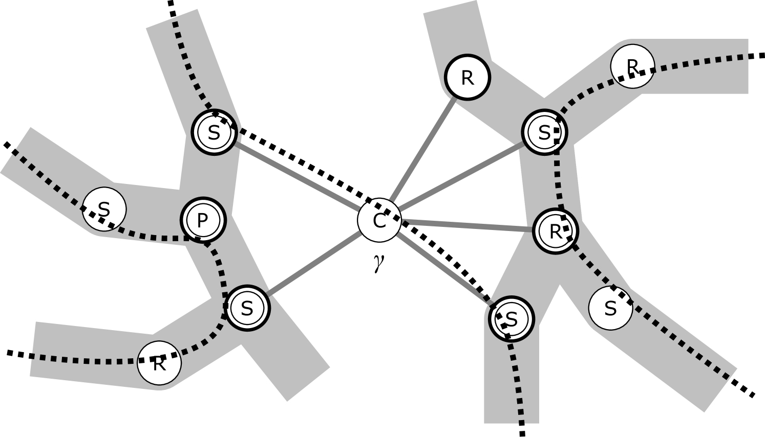
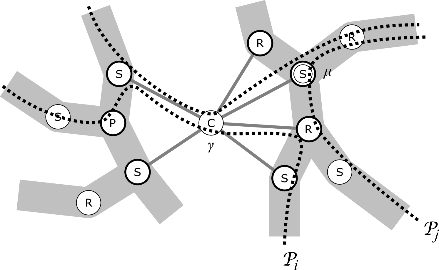
(b) For each of the three con-paths, we mark those of their nodes with a double circle for which is a substitute.
Lemma 5
Let be a connected planar graph, be a set of indices, and , , be a collection of con-paths in the decomposition graph (as derived from an arbitrary collection of con-chains in ). Then there exists and such that, for all , the following holds: if , then or contains a substitute for w.r.t. .
Note that different ’s in the statement may have different substitutes for , but there are at most four available substitutes for w.r.t. anyway (one for each vertex of the two virtual edges of the neighbors of on ).
Proof
We would like to apply Claim 3.3 but is not a tree (due to adjacencies of the C-nodes, see Definition 2.6 and Figure 2(c)). Consider a C-node of a cut vertex of . If is a block of incident with , then the set of all mates of in induces a subtree . We construct a spanning tree as follows:
-
•
For every C-node of and each incident block , we delete all but (an arbitrary) one of the edges of between and .
-
•
For each , , such that passes through any such and one of its deleted edges, we reroute as along the remaining edge (between and ) and through . Otherwise, let .
Now we apply Claim 3.3 onto and the paths , , obtaining a pair and . We analyze the situation with respect to and .
-
•
If , then we set . Otherwise, is not a C-node and there is a C-node such that is a mate of the cut vertex of ; then, we set to be the neighbor of on corresponding to (i.e., is the first node in when traversing starting at and away from ).
-
•
If, for any , then ; this is since by our construction. (Though, the converse direction is not true in general.) Consequently, our analysis only has to consider those indices for which and .
-
•
If then we are done. This is true, in particular, when is a C-node. Hence, in addition to the previous paragraph, we may now assume that is not a C-node and . Let be the block of such that .
-
•
If then, since , the path has been rerouted from original at a C-node such that . Let be the neighbor of on ( is the only node of in ). Since intersects and has no cycles, it is . Consequently, is a substitute for w.r.t. by definition.
-
•
It remains to consider, in addition to the previous, that . In this case the C-node has been defined above; we have and is a substitute for w.r.t. . So, if then we are done. Hence , and (a) intersects in in a node , or (b) is disjoint from in but they intersect in a C-node incident with the block .
Consider case (a); since the only connection from to in contains (and ), there again has to be a C-node such that , and consequently and is a substitute for w.r.t. , too. In case (b), contains a path from to (since has only one edge to in ), while the -neighbor of in belongs to . Therefore, and so by minimality. Then is a substitute for w.r.t. . ∎
An application of Lemma 5 in the aforementioned -defect argument brings another elusive problem; namely, what should be the subpaths of selected to which the argument is applied? The crucial property we need is that every con-path hitting does so in the starting node of .
Informally, for and as in Lemma 5 we let be the minimal subpath intersecting all the con-paths not disjoint from . Then can be chosen as the subpaths edge-disjoint from such that . However, we also have to consider possible defects (an unbounded number of?) due to honoring the preferences of . Let be the ends of . We will show that each of the corresponding skeletons shares a vertex with (formal details given later). Consequently, only at most two repair operations (at these shared vertices) are enough for the whole insertion path along , while the individual preferences along are simply ignored in the algorithm (Remark 3). This accounts for at most dirty passes along whole , as desired.
Finally, addressing Remark 6 b is actually not that difficult, and we informally outline the idea now. Choose any node of and focus exclusively on and the con-paths passing through it, in other words, on the multiset of (selected) individual preferences at from Algorithm 3.3. Let be the individual preference chosen in the algorithm.
Without loss of generality we may assume that the repeated application of Lemma 5 selects and removes con-paths in the order . We define and, for , (with multiplicity). The intuitive problem with a naïve voting scheme (that would consider the full sets instead of ) is that it would be performed over at each node ; our repeatedly applied counting argument based on Lemma 5, however, requires a voting according to the corresponding at each step.
This can be seen as follows: If then the multiplicity of in is and, informally, we can afford to pay for one repair operation at within the -defect argument. Otherwise (), no repair operation is needed.
For , when or the multiplicity of in is , the argument is fine again. Consider the contrary, that and so the multiplicity of in is , while the multiplicity of in is . This may happen, though, it is an easy exercise to show that every such can be accounted towards some such that and the multiplicity of in is . In the latter case of , the -defect argument reserved one repair operation at for but it was not required there. In the formal proof below, we will say that issues a “repair ticket” at which is subsequently used by for an actual repair operation.
We are finally ready to prove our stronger bound. First, we define what implementation of step 3 of Algorithm 3.3 is needed to get our stronger bound.
Definition 3.4 (Ignoring some individual preferences based on a good simplicial sequence)
Consider the decomposition graph of a connected planar graph , and con-paths in .
-
i)
For any permutation of the indices, we say that a sequence , where , is a good simplicial sequence if the following holds true for :
-
•
for , the choice and satisfies the conclusion of Lemma 5.
-
•
-
ii)
Let be defined as in Algorithm 3.3. We say that a system of sets , , ignores the sequence if the following holds true for and all of :
-
•
if , then if and only if one of the following holds true; , or is a C-node neighboring on , or there is a cut vertex of such that both and are mates of .
-
•
Note that a good simplicial sequence always exists by Lemma 5, but it may not be unique (which is not a problem for our arguments). Also observe that our , as now defined in Definition 3.4, “ignores” many more individual preferences than originally suggested in the aforementioned sketch of the proof idea. This allows for a simpler definition and does not hurt the argument. Most importantly, Definition 3.4 ii is invariant on the order of the simplicial sequence—we only use information that a certain node is assigned to , when defining .
Proof
We assume all the notation of Algorithm 3.3. We may also assume, without loss of generality, that the good simplicial sequence considered when defining is . Recall that the actual order of pairs in this sequence is significant only for the following analysis and it is not used in any way in Algorithm 3.3, when defining . Denote by .
For in this order, we argue as follows. By Definition 3.4, . Let be the ends of . Denote by the node closest to on and such that , and by the one closest to such that . We observe, by Definition 3.4, that the skeleton of (and analogously ) has a common vertex with the skeleton of . Let denote the subpaths of from to , and from to . If or , then or is undefined and hence the following argument is simply skipped for it.
Note that if both are defined. The subsequent argument will be given only for , with understanding that the same symmetrically applies to .
By Lemma 5 and the definition of a substitute, if a con-path , , intersects , then contains or , or intersects . Hence, by Claim 2.2, if intersects then , and so we have where denote the nodes of (of length ) in this order. For let denote the subset of those for which is coherent with at or . We say that node is divergent for on level if is not an R-node and .
Our key observation is that the number of nodes of that are divergent for on level , is at most : whenever a node is divergent we have, by the definition of coherence, if is not an R-node, and if is an R-node (recall that R-nodes are not counted as divergent). This upper bound of divergent nodes along will be used to bound the total defect of in honoring the computed optimal embedding preferences of edges in .
Let . If then, by the definitions and the semi-majority choice in the algorithm, is divergent for on level . Unfortunately, it might happen that is divergent for on level but not divergent for on level , and we cannot simply account for the cost of this defect at on the same level . To resolve such cases, we use an amortized analysis which “borrows” for the cost from smaller levels. This is formalized as follows:
-
I)
If is divergent for on level , then we issue one repair ticket to (the total number of tickets issued along is thus at most , as desired).
-
II)
If , then we use one of the repair tickets issued to towards a total defect in honoring the optimal preferences of restricted to .
-
III)
Let be such that and define
After finishing steps (I) and (II) on level , the number of available (i.e., issued and not yet used) repair tickets for is at least .
We claim that this amortized analysis is sound, more precisely, that every time we would like to use a repair ticket in (II), there is one available. In a “simple” situation, step (II) would simply use the ticket just issued in (I) on the same level (this happens, e.g., for ). Assume that no ticket is issued on level , which means that is not divergent for , and so . If , then and so . By (III), we have got an available repair ticket from one of the previous levels for use on level .
It is thus enough to prove (III) by induction on . For the base case (i.e., before the process starts), we have by the semi-majority choice of . Further on, let be such that . It suffices to discuss the inductive step in two cases, either or :
-
•
Assume . Since and , we have . Then and is divergent for on level . Consequently, the repair ticket issued in (I) on level is not used in (II) and, indeed, there are at least available repair tickets afterwards.
-
•
Assume that and a repair ticket is used in (II) on level since . Then and so . Consequently, and hence is again divergent for on level . This means a repair ticket for (II) has just been issued in (I) on level .
Claim (III) is finished.
Altogether, we have issued at most repair tickets along , and also at most tickets along . Furthermore, two special repair tickets are issued to , summing up to at most for iteration . For the whole problem, altogether at most repair tickets are issued. We are hence nearly finished and it remains to prove that the above distributed repair tickets are sufficient for all the “repair operations” carried out when drawing the edges of into .
Again for (the order is now irrelevant), we argue as follows. By Definition 3.4, the skeletons of and must share a vertex ( is a cut vertex of if but this is not important now). We analogously set on the side of . Now, is the con-path of and is the con-path of . By Claim 3.1(b), the preferences , which are the restriction of to , are optimal embedding preferences of . The embedding hence honors with defect at most equal to the number of repair tickets used along —we denote this number by . We define and analogously.
By Lemma 3, we can draw the new edges into , constructing with crossings. Furthermore, the new edge can be drawn into with crossings—this may actually be a nonzero number if is an R-node, but there are no embedding preferences for such R-nodes anyway, as their skeleton embeddings are not mutable. Altogether, is drawn with crossings.
Using the same argument as in the proof of Lemma 3, we now perturb the path formed by the edges in into a drawing of the edge in . For this, we require at most additional crossings. The number of crossings in is hence at most using Claim 3.1(a).
While neglecting the at most crossings between the edges of , we get that the total number of crossings between and is at most
This concludes the proof. ∎
3.4 Tightness of the Analysis of Algorithm 3.3
Reading the fine-grained analysis of Algorithm 3.3 in Theorem 3.5, it is natural to think whether perhaps the ideas can be improved further, giving an even tighter guaranteed relation between the outcome of the algorithm and the sum of the individual insertion values than (7). This is, however, not possible as we now show by exhibiting an asymptotically matching lower bound in Proposition 2.
Proposition 2
For any integers and , there exist instances of the problem such that , , , and
| (8) |
where .
Note, though, that this lower bound only concerns the relation between the optimum value and the simple lower bound we use in our analysis; it does not say anything about approximability (or inapproximability) of the MEI problem itself. The main message of this claim hence is that if one wants to achieve an algorithm with a tighter approximation guarantee for the MEI problem, then one must consider something more than just the individual insertion solutions.
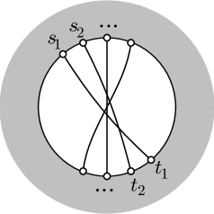
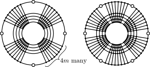
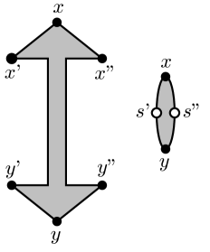
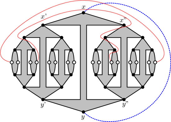
Proof
We are going to present three separate constructions. They can then be easily combined together by adjusting them appropriately to and adding dummy edges between them (to satisfy connectivity of ):
-
I)
There exists a planar graph and a vertex pair such that and .
-
II)
There exists a planar graph and a set of vertex pairs , such that each is planar, , and .
-
III)
There exists a planar graph and a set of vertex pairs , such that each is planar, , and .
In (I), we take as a sufficiently large plane hexagonal grid, and select two edges in that are sufficiently far from each other and from the grid boundary; the vertices then subdivide the selected edges.
In (II), we assume to be any dense and large enough triconnected graph with a face of length . Labeling the vertices on this face in clockwise order, gives an instance that clearly requires crossings. See Figure 3(a) for an illustration.
We concentrate on the most interesting construction (III). Since the bound in (8) is of asymptotic nature, we may without loss of generality assume that is even and divisible by , and that for some integer .
Let , , be any dense enough planar graph with special marked vertices , each of degree exactly , such that the following conditions hold. Up to mirroring and reordering of parallel edges, allows only a unique plane embedding of . Every such embedding has a unique face, called active, incident with all of in this order; no other face of is incident with more than one of . Moreover, assume we embed new bar edges (only if ) into the active face of ; this divides the active face into (or ) sectors. We require that if we draw any curve with the ends in distinct sectors and not crossing the bar edges, then makes at least crossings with the edges of . If the two sectors holding the ends of are not next to each other and avoids all other sectors, then makes at least crossings.
The desired properties of are for instance achieved by the graphs depicted in Figure 3(b), where the marked vertices are drawn white, the outer face is the active face, and each drawn line represents a bunch of parallel edges.
Our recursive construction of for (III) is schematically depicted in Figure 3(d). Recalling , we define a graph with two special vertices called the poles, by induction on . In the base case, , is a copy of with the marked vertices in this order around the active face, such that are the poles of . Having constructed and its disjoint copy , we define as follows: take a copy of (the bolt) with the marked vertices in this order (see Figure 3(c)), make the new poles of , and identify with the two poles of and with the two poles of .
The graph has marked vertices that are copies of from (the white terminals in Figure 3(c)), and we denote them by (in any order). We analogously denote by the corresponding vertices in . Finally, we let and .
It should be understood that the embedding possibilities for are essentially defined by the binary flipping decisions of each R-node skeleton corresponding to a copy of or in the construction. Furthermore, for each , the edge can be inserted into (some embedding of) without crossings and into any fixed embedding of with at most crossings. See the red dotted edges depicted in Figure 3(d). To settle (III) it remains to argue that , which we achieve in two steps. Let denote the solution value of the problem without counting the crossings between edges of .
Claim
Let be the graph obtained from by adding a bunch of parallel edges between the two poles of (cf. the blue dashed curve in Figure 3(d)). Then .
We have since both poles of share a common face in the corresponding optimal solution and each edge of traverses any face of embedded at most once. Routing the edges of via hence gives at most additional crossings per edge of . Conversely, consider an optimal solution of value and an edge . We claim that after removing from this solution, we “save” at least crossings on .
If crossed all of , then we are done. Otherwise, by the property of , the drawing of has to enter both the sectors of the bolt of incident to the poles (and so has additional crossings in between), or there are at least crossings on . In both cases one requires by at least less crossings on in the subembedding of .
Claim
and .
By Claim 3.4, it is enough to prove one of the inequalities but it is convenient to consider both of them by indunction on . The base case of () is a degenerate extension of the previous, defining to be the two opposite marked vertices of , and it is trivial.
Stepping from to ; we consider and an optimal solution of value inserting the edges of into a plane embedding of , without counting crossings inside . Let be a curve drawn between the poles of without crossing its edges (e.g., the blue dashed curve in Figure 3(d)). Similarly as in the proof of Claim 3.4, we can show that there is an optimal solution in which every edge of has to cross .
Let and be the subembeddings of the two recursive copies of in . We cut every curve of the edges of at a point in the intersection with , to obtain curve parts, of which are incident to . These latter parts can be paired such that the pairs (after reconnection along ) form a set of edges with ends in and the instance is as in the inductive assumption for . By the property of , the bolt of can play the role of in Claim 3.4; let denote augmented with the bolt. We hence have that the curve parts of incident to have at least crossings with edges of by our (second claim of the) inductive assumption. Since the same symmetrically holds for the curve parts incident to , summing together we get that , as desired. ∎
3.5 Runtime of Algorithm 3.3
Thanks to using well-known building blocks, the overall runtime bound of our algorithm is actually rather simple to see. Let . As mentioned in Section 2, we can build the con-tree (step 1) in linear time , based on the linear-time decomposition algorithm [22]. Recall that . In step 2, we call the (deterministic) insertion algorithm times.
In step 3, computing for all is trivial in , as is achieving the weak estimate by setting, e.g., . To achieve the strong estimate, we can compute a simplicial sequence (Claim 3.3) via BFS-traversals in time. Thereby, we also identify node substitutes (Lemma 5) and decide which preferences to ignore (Definition 3.4).
In step 4, we can compute for each of the con-tree nodes via semi-majority vote in time. Computing the embedding based on these preferences takes only linear time . Hence, also this step requires time.
4 Crossing Number Approximations
Our main concept of interest is the crossing number of the graph . We can combine our above result with a result of [9], connecting the optimal crossing number with the problem of multiple edge insertion.
Theorem 4.1 (Chimani et al. [9])
Consider a planar graph and an edge set , . The value of an optimal solution to satisfies
where denotes the (optimal) crossing number of the graph including the edges , and thereby accounts for crossings between the edges of .
Notice that, when considering the crossing number problem of , we may assume to be connected—otherwise we could “shift” some edges of to . Let , . Plugging the estimate of Theorem 4.1 into the place of in Theorem 3.5, and realizing that the term in both estimates stands for the same set of crossings, we immediately obtain
Hence we can give the outcome of Algorithm 3.3 as an approximate solution to the crossing number problem on , proving:
Theorem 4.2 (Theorem 1.2(5))
Given a planar graph with maximum degree and an edge set , , , Algorithm 3.3 computes, in time, a solution to the problem with the following number of crossings
∎
A note on approximating the crossing number of surface-embedded graphs.
In [19], an algorithm is presented to approximate the crossing number of graphs embeddable in any fixed higher orientable surface. This algorithm lists the technical requirement that has a “sufficiently dense” embedding on the surface. Yet, as noted in [19], a result like Theorem 4.2 allows to drop this requirement: If the embedding density is small, then the removal of the offending small set(s) of edges is sufficient to reduce the graph genus, while the removed edges can be later inserted into an intermediate planar subgraph of the algorithm.
5 A Note on the Planarization Heuristic and the Practicality of our Algorithm
The currently practically strongest heuristic [17] for the crossing number problem is the planarization heuristic which starts with a maximal planar subgraph of the given non-planar graph, and then iteratively performs single edge insertions. The crossings of such an insertion are then replaced by dummy nodes such that each edge is inserted into a planar graph. Due to its practical superior performance, often giving the optimal solution [5, 15], it was an open question if this approach unknowingly guarantees some approximation ratio.
By investigating our strategy and proofs, it becomes clear that this approach as such cannot directly give an approximation guarantee: by routing an edge (in an R-node) through another virtual edge (representing a subgraph ) and replacing the crossings with dummy nodes, you essentially fix (most of) the embedding of . This fix might result in embedding restrictions for further edge insertions, without having an edge in that requires this embedding. Therefore the number of dirty passes can no longer be bounded by a function in .
Yet, an implementation realizing the planarization heuristic already contains all the ingredients to obtain our approximation; one “only” has to compute all the embedding preferences and merge them according to Algorithm 3.3, steps 3 and 4, before running the fixed-embedding edge insertion subalgorithm for all inserted edges. In fact, such an implementation is described in [6], where, in a nutshell, it is shown that this algorithm is much faster then the best postprocessing-heavy planarization-based heuristics, while producing roughly equally good solutions.
6 Conclusions
We have presented a new approximation algorithm for the multiple edge insertion problem which is faster and simpler that the only formerly known one [11], while at the same time giving better bounds; in fact, in contrast to the former multiplicative approximation, it is the first one with an additive bound. Our algorithm directly leads also to improved approximations (even with constant ratio for a large class of inputs) for the crossing number problem of graphs in which a given set of edges can be removed in order to obtain a planar subgraph, and for graphs that can be embedded on a surface of some fixed genus.
We conclude with an interesting open problem. We know that multiple edge insertion is NP-hard when the number of inserted edges is part of the input, and it is linear time solvable for the special case of inserting a single edge. What is the complexity of optimally inserting a constant number of edges?
References
- [1] S. N. Bhatt and F. T. Leighton. A framework for solving vlsi graph layout problems. J. Comput. Syst. Sci., 28(2):300–343, 1984.
- [2] D. Bienstock and C. L. Monma. On the complexity of embedding planar graphs to minimize certain distance measures. Algorithmica, 5(1):93–109, 1990.
- [3] S. Cabello and B. Mohar. Crossing and weighted crossing number of near planar graphs. In Proc. GD ’08, volume 5417 of LNCS, pages 38–49. Springer, 2008.
- [4] S. Cabello and B. Mohar. Adding one edge to planar graphs makes crossing number hard. In Proc. SoCG ’10, pages 68–76. ACM, 2010.
- [5] M. Chimani. Computing Crossing Numbers. PhD thesis, TU Dortmund, Germany, 2008. Online, e.g., at www.cs.uos.de/theoinf.
- [6] M. Chimani and C. Gutwenger. Advances in the planarization method: Effective multiple edge insertions. J. Graph Algorithms Appl., 16(3):729–757, 2012.
- [7] M. Chimani, C. Gutwenger, P. Mutzel, and C. Wolf. Inserting a vertex into a planar graph. In Proc. SODA ’09, pages 375–383, 2009.
- [8] M. Chimani and P. Hliněný. A tighter insertion-based approximation of the crossing number. In Proc. ICALP ’11, volume 6755 of LNCS, pages 122–134. Springer, 2011.
- [9] M. Chimani, P. Hliněný, and P. Mutzel. Vertex insertion approximates the crossing number for apex graphs. European Journal of Combinatorics, 33:326–335, 2012.
- [10] J. Chuzhoy. An algorithm for the graph crossing number problem. In Proc. STOC ’11, pages 303–312. ACM, 2011.
- [11] J. Chuzhoy, Y. Makarychev, and A. Sidiropoulos. On graph crossing number and edge planarization. In Proc. SODA ’11, pages 1050–1069. ACM Press, 2011.
- [12] G. Di Battista and R. Tamassia. On-line planarity testing. SIAM Journal on Computing, 25:956–997, 1996.
- [13] G. Even, S. Guha, and B. Schieber. Improved approximations of crossings in graph drawings and VLSI layout areas. SIAM J. Comput., 32(1):231–252, 2002.
- [14] I. Gitler, P. Hliněný, J. Leanos, and G. Salazar. The crossing number of a projective graph is quadratic in the face-width. Electronic Notes in Discrete Mathematics, 29:219–223, 2007.
- [15] C. Gutwenger. Application of SPQR-Trees in the Planarization Approach for Drawing Graphs. PhD thesis, TU Dortmund, Germany, 2010.
- [16] C. Gutwenger and P. Mutzel. A linear time implementation of SPQR trees. In Proc. GD ’00, volume 1984 of LNCS, pages 77–90. Springer, 2001.
- [17] C. Gutwenger and P. Mutzel. An experimental study of crossing minimization heuristics. In Proc. GD ’03, volume 2912 of LNCS, pages 13–24. Springer, 2004.
- [18] C. Gutwenger, P. Mutzel, and R. Weiskircher. Inserting an edge into a planar graph. Algorithmica, 41(4):289–308, 2005.
- [19] P. Hliněný and M. Chimani. Approximating the crossing number of graphs embeddable in any orientable surface. In Proc. SODA ’10, pages 918–927, 2010.
- [20] P. Hliněný and G. Salazar. On the crossing number of almost planar graphs. In Proc. GD ’05, volume 4372 of LNCS, pages 162–173. Springer, 2006.
- [21] P. Hliněný and G. Salazar. Approximating the crossing number of toroidal graphs. In Proc. ISAAC ’07, volume 4835 of LNCS, pages 148–159. Springer, 2007.
- [22] J. E. Hopcroft and R. E. Tarjan. Dividing a graph into triconnected components. SIAM Journal on Computing, 2(3):135–158, 1973.
- [23] S. Masuda, K. Nakajima, T. Kashiwabara, and T. Fujisawa. Crossing minimization in linear embeddings of graphs. IEEE Trans. Comput., 39:124–127, 1990.
- [24] W. T. Tutte. Connectivity in graphs, volume 15 of Mathematical Expositions. University of Toronto Press, 1966.
- [25] I. Vrt’o. Crossing numbers of graphs: A bibliography. ftp://ftp.ifi.savba.sk/pub/imrich/crobib.pdf, 2011.
- [26] T. Ziegler. Crossing Minimization in Automatic Graph Drawing. PhD thesis, Saarland University, Germany, 2001.
Appendix 0.A Ziegler’s proof of NP-hardness of MEI
In his PhD-thesis [26], Ziegler showed that MEI is NP-hard (the corresponding decision problem is NP-complete) for general . Since this thesis is somewhat hard to obtain, we reproduce a slightly simplified version of his proof.
Theorem 0.A.1 (Ziegler [26])
Given a graph , a set of unordered vertex-pairs, and an integer , it is NP-complete to decide whether there is a planar drawing of such that we can insert an edge for each vertex pair into with overall at most crossings.
Proof
NP-membership is trivial and it hence remains to show NP-hardness. We use a reduction from
Fixed Linear Crossing Number (FLCN):
Given a graph , a 1-to-1 function , and an integer . Does there exist an -linear drawing of with at most crossings?
Thereby, an -linear drawing is one where all vertices are placed on a horizontal line, each vertex at coordinate , and each edge is either drawn completely above or completely below that line. It was shown in [23] that Flcn is NP-complete.
Let be an instance to FLCN. We will construct a corresponding MEI instance of size polynomial in which is a yes-instance for MEI if and only if is a yes-instance for FLCN. The key idea is to build a rigid graph that models the restrictions of -linear drawings, into which we then have to insert the original edges . Observe that FLCN can only be hard if .
Label the vertices such that and . We may assume w.l.o.g. that . We start with constructing a graph on vertices where and . Observe that is planar and (since its SPR-tree consists of one R- and one S-node) allows only a unique embedding (and its mirror). We obtain from by replacing each edge in by parallel edges. Up to ordering the multiple edges amongst its peers, still allows only a unique embedding.
Now, set and , i.e., we want to insert the edges of into planar . We can assume w.l.o.g. that contains no edges or for any . has exactly four faces with more than two incident vertices: let () be the face incident to exactly (, respectively). Let () be the face incident to all of and (, respectively). To go from one of these four faces to another, we would always have to cross at least edges (a parallel bunch), which is infeasible when asking for a solution with at most crossings. No edge of will be placed in or as they are only incident to one vertex of . Hence each edge is either completely within or , and the equivalence with being above or below the horizontal line of an -linear drawing follows.∎