Anytime Control under Practical Communication Model
Abstract
††W. Liu, Y. Li and B. Vucetic are with School of Electrical and Information Engineering, The University of Sydney, Australia. Emails: {wanchun.liu, yonghui.li, branka.vucetic}@sydney.edu.au. D. E. Quevedo is with the School of Electrical Engineering and Robotics, Queensland University of Technology (QUT), Brisbane, Australia. Email: daniel.quevedo@qut.edu.au.We investigate a novel anytime control algorithm for wireless networked control with random dropouts. The controller computes sequences of tentative future control commands using time-varying (Markovian) computational resources. The sensor-controller and controller-actuator channel states are spatial- and time-correlated, and are modeled as a multi-state Markov process. To compensate the effect of packet dropouts, a dual-buffer mechanism is proposed. We develop a novel cycle-cost-based approach to obtain the stability conditions on the nonlinear plant, controller, network and computational resources.
Index Terms:
Control over communications, nonlinear systems, stability of nonlinear systems, Markov fading channels.I Introduction
During past decades, significant attention has focused on embedded or networked control systems that have limited and time-varying controller’s computation capability due to high requirements on multitasking operations. In particular, assuming constant and limited computational resources, bounds on computational time of specific optimization algorithms for achieving stability were derived in [1, 2]. For time-varying computational resources, a dynamic computation task scheduling method was proposed for model predictive controllers [3]. On-demand computation scheduling of control input based on plant states were investigated for periodic, event-triggered and self-triggered policies in [4, 5, 6], respectively.
Another stream of research considers anytime algorithms for robust control and making efficient use of time-varying computational resources. In general, an anytime algorithm can provide a solution even with limited computational resources, and refines the solution when more resources are available. In the pioneering work [7], an anytime control system was proposed, where the number of updated states varies with the available computation time known to the controller a priori. In [8], an anytime control algorithm for a multi-input linear system was proposed for the scenario when the computation availability is unknown a priori. The main idea was to first calculate the most important component of the control vector and then calculate the less important ones as more computational resource becomes available. In [9], a sequence-based anytime control method was proposed, which can calculate a tentative sequence of future control input for as many time steps as allowed by the available computational resources at each time step. The pre-calculated control sequence can compensate for the time steps when no computational resource is available for control calculations. Following this work, sequence-based anytime control systems with Markovian processor availability, event-triggered sensor updates and multiple control laws were investigated in [10, 11, 12], respectively. In [7, 8, 9, 10], the sensor-controller and controller-actuator channels were assumed to be perfect and error-free. In [11] and [12], the sensor-controller channel was assumed to have independent and identically distributed (i.i.d.) packet dropouts222Note that i.i.d. packet dropout channel is very commonly considered in the literature of networked control [13]., i.e., only binary-level (on-off) channel states, were considered, while the controller-sensor channel was assumed to be perfect.
Motivation. The existing work of anytime control [7, 8, 9, 10, 11, 12] cannot effectively handle the fully distributed networked control scenario, where both the sensor-controller and controller-actuator communication links are wireless. Moreover, the existing research only considered simple wireless channel models, which cannot capture the key features of practical wireless channels that are time-varying and correlated [14]. Therefore, anytime control design and analysis for fully distributed networked control system in practical wireless channels are critical in practice, but also present new challenges.
Novelty and contributions. In this work, we consider for the first time the sequence-based anytime control of a wireless networked control system (WNCS) in a generalized dual imperfect channel, where the sensor-controller and controller-actuator channel states are spatial- and time-correlated and are modeled as a multi-state Markov process. Different from most of the existing works [9, 10, 11, 12], where only the controller has a buffer to keep the calculated sequence of control inputs, we propose to use anytime control with buffers at both the controller and the actuator nodes. The latter is used to compensate for dropouts in the controller-actuator channel. Moreover, the available computational resource of the controller is allowed to be time-correlated, modeled as a multi-state Markov process. Such a dual-channel-dual-buffer anytime control system has practical advantages but brings significant challenges to its analysis due to the complex system state updating rule, compared to previous setups. We propose a novel cycle-cost-based approach to derive sufficient conditions for stochastic stability of the overall WNCS. Our stability conditions are stated in terms of plant dynamics, network dynamics, buffer properties and computational resource dynamics. We further show that, under suitable assumptions, the conditions derived guarantee robust stability when plant disturbances are taken into account.
The remainder of the paper is organized as follows: Section II presents the system model of anytime control in the dual-channel-dual-buffer WNCS. Section III develops the stability condition. Section IV provides robust stability analysis. Section V draws conclusions.
Notation: Sets are denoted by calligraphic capital letters, e.g., . denotes set subtraction. Matrices and vectors are denoted by capital and lowercase upright bold letters, e.g., and , respectively. is the expectation of the random variable . The conditional probability if . is the matrix transpose operator. is the Euclidean norm of vector . and denote the sets of positive and non-negative integers, respectively. denotes the -dimensional Euclidean space. and denote the element at the th row and th column of a matrix , and the th element of a vector , respectively. denotes the spectral radius of . denotes the diagonal matrix generated by the vector . denotes the semi-infinite sequence . A function is of class- () if it is continuous, strictly increasing, and zero at zero. and denotes the all-zero and matrices, respectively. indicates that has all zero elements.
II Anytime Control in a Dual-Channel-Dual-Buffer WNCS
We consider a WNCS consisting of a plant system, a remote controller and a wireless network placed between the plant and the controller. A sensor sends its measurements of the plant to the controller, and the controller computes and sends control commands to a remote actuator via the wireless network as illustrated in Fig. 1. The dual wireless channel (i.e., the sensor-controller and controller-actuator channels) setup is different from [10, 11, 9], which assumed either perfect transmissions in two channels or a single (imperfect) wireless channel from the sensor to the controller.
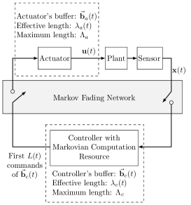
Each sampling period of the plant, denoted by , is divided into four phases: sensor-controller (S-C) transmission, command computation, controller-actuator (C-A) transmission and implementation of control as illustrated in Fig. 2.

We consider a process-noise-free discrete-time non-linear plant model
| (1) |
where and are the plant state and the control input at time . Note that a more practical model with process noise will be investigated in Section IV.
As a consequence of stochastic computational resources at the controller and packet dropouts in the sensing and control channels (which will be described later in more detail), the plant may have to operate in open loop for arbitrarily long time intervals. This may lead to performance degradation and potential loss of stability. Thus, throughout this work we will analyze the stability conditions of the considered system where the stability is defined as follows.
Definition 1.
The process-noise-free dynamical system (1) is stochastically stable, if for some , the expected value .
Our standing assumption is that the plant is globally controllable (in the idealized closed loop case):
Assumption 1 ([10, 11, 9]).
There exist functions , a constant , and a control policy , such that for all
II-A Dual Markov Fading Channels
We consider wireless fading channels for the S-C and C-A transmissions [15, 16, 17], where wireless channel status varies with time due to multi-path propagation and shadowing caused by obstacles affecting the radio-frequency (RF) wave propagation. The time-varying channel conditions can be modeled as Markov processes [14]. Furthermore, in practice, the two channel conditions can be correlated, named as spatial correlation, which is caused by the same environment obstacles [18].
For wireless packet transmissions, there exists a fundamental tradeoff between reliability, i.e., the packet drop probability, and data rate, which determines the amount of information bits that a packet can carry [19]. For a fixed channel condition, increasing the data rate of a packet can lead to a higher packet drop probability. For a good channel condition, one can reduce the packet drop probability while maintain the fixed data rate. Alternatively, one can increase the data rate while maintaining the packet drop probability [20]. In this work, we will keep the data rate fixed for the S-C transmissions, since there is nothing gained from aggregating past sensor measurements in the state feedback case. However, it is well known that sending control sequences can be beneficial to compensate for packet dropouts. To accommodate this in a fading channel environment, we allow C-A transmissions to contain packets of varying data rate. The rates depend on the channel condition and provide a guaranteed packet-dropout probability. Thus, a longer control sequence can be transmitted to the actuator under a better channel condition with the same reliability.
C-A channel. At time slot , the controller can at most transmit commands to the actuator with a guaranteed packet drop probability . In other words, denotes the C-A channel quality. In this sense, can be treated as the capacity of the channel under the packet drop probability requirement . Let and denote the successful and failed transmissions in time slot .
S-C channel. At time slot , the S-C channel power gain takes values from . Let denote the index of the channel power gain. Thus, denotes the S-C channel quality. Let and denote the successful and failed transmissions in time slot . The packet drop probability at time is
| (2) |
where is the packet drop probability function in terms of the channel power gain.
Then, we assume that the joint C-A and S-C channel condition is a time-homogeneous Markov process, and the state transition probability is given as
| (3) | ||||
Remark 1.
Our current channel model jointly considers both the spatial-correlated S-C and C-A channels, the time-correlated fading channel conditions and variable data rate requirements. To the best of our knowledge, this has never been considered in the literature of WNCSs and is more general than existing models. For example, independent dual channels with i.i.d. packet dropouts were considered in [21], which is a special case of our model when the fading channels degrade to static ones and the channels’ spacial correlation is perfectly canceled.
II-B Anytime Control with Dual Buffers
When considering perfect transmission between the controller and the actuator, as in [10, 11, 9], the system only needs one buffer at the controller to store the computed control commands. If imperfect transmissions are taken into account, it is convenient to include a command buffer at the actuator to provide robustness against packet dropouts, see e.g. [22] for a general packetized predictive control method333Markovian communication and computational resources were not considered in [22].. Clearly, the dual-buffer system introduces a more complex state updating process.
Let and denote the length of the controller’s and the actuator’s buffer, respectively. Then, the buffer state at the controller after its transmission phase is denoted as
| (4) |
where . The buffer state at the actuator right after the C-A transmission but before the implementation of a control command, i.e., the pre-control buffer, is denoted as
| (5) |
where . In general, the buffers and keep the calculated sequences of control command, and the buffer updating rules will be given in the following part.
The control input is the first element in the actuator’s buffer, i.e.,
| (6) |
which can be treated as the previously predicted control command for the current time slot. The buffer state at the actuator right after the control implementation, i.e., the post-control state, is
| (7) |
where the buffer shift matrices are defined as
| (8) |
Let denote the number of calculated tentative future control commands at time . The process is a time-homogeneous Markov process with the transition probability
| (9) |
where . It is assumed that .
The controller’s operations are described as
-
1.
If , the controller has a new update from the sensor and is available for computation. In this case, it discards all the existing commands in its buffer and generates a sequence of control commands to control the plant in time slots to . The sequence of tentative controls is
(10) The buffer state before transmission is written as
Specifically, the controller calculates the control sequence based on the anytime control algorithm proposed in [9], which is rewritten as
(11) where is defined in Assumption 1.
Considering the C-A channel capacity and the actuator’s buffer length, the controller transmits commands to the actuator. If the transmission is successful, the buffer shifts by steps. Otherwise, the controller erases its buffer. This is because the first computed control command cannot be implemented in the current time slot , and the rest of computed control commands, which are calculated based on the successful implementation of the first control command, become useless. It is clear that at time instances where the actuator has run out of buffer contents, we have and . For the case that , the predicted control input is equal to currently calculated control command only in the perfect process-noise-free scenario, and in general.
-
2.
If , the controller does not have a new update from the sensor. In this case, it does not generate any new control command. If , the controller does not have the computational resource to generate any new control command.
In these two cases, if the plant is out of control in the previous time slot, i.e., , the controller erases its buffer due to the same reason in case 1); otherwise, the controller sends the buffered commands to the actuator as much as it can, subject to the constraints of the C-A channel capacity and the actuator’s buffer length.
The actuator’s operations are described as
-
1.
If , the actuator’s buffer is shifted by one step, i.e., , since the first command in the buffer of the previous time slot was used for control.
-
2.
If and , the actuator erases the previous commands and stores the received ones. This is because the newly calculated control commands are expected to perform better than the previous calculated commands, especially when the process noise has a large variance. 444 Note that when the number of tentative future commands in the newly received packet is less than the previous ones, we still need to erase all the previous commands, not just part of them. The reason is that each buffered control command at the actuator was calculated assuming the successful implementation of the previously calculated control command. Thus, if the first few control commands at the actuator’s buffer are removed (i.e., cannot be applied for control), then the rest of the buffer is of little use.
-
3.
If and , no operation on the actuator’s buffer is required as there is no new commands transmitted.
-
4.
If , and , the actuator shifts its buffer by one step due to the same reason in 1) and stores the received commands in the buffer right after the existing commands.
Let and denote the effective buffer lengths at the controller and the actuator, respectively. Intuitively, and jointly determine the closed-loop performance of plant, as a larger and a larger indicate that the plant will be delivered tentative control values for a longer time. Based on the controller’s and the actuator’s operations, the actuator is not necessary to have a larger buffer than the controller. Thus, we assume that .
Let denote the number of tentative commands to be transmitted. Based on the controller’s operations, can be written as
| (12) |
Then, the buffer-updating rules based on the controller’s and the actuator’s operations are
| (13) |
and
| (14) |
III Stability of the Anytime Control System
Based on the anytime control method described in (12), (13) and (14), and following the established stability analysis framework adopting stochastic Lyapunov functions [10, 11, 9], to investigate the stability condition of the system (1), we only need to focus on the plant events that the actuator runs out of control commands, i.e., . However, since the process has an infinite memory and is not a Markov process, the methods in [10, 11, 9] are not directly applicable. Instead, we shall analyze the control system through the aggregated Markov process defined as
| (17) | ||||
where and . Assume that , belongs to the finite set with cardinality . Different from [10], which only needs to analyze an aggregated process of two processes, we need to investigate the aggregation of five processes, where both and are correlated with .
Since the control process is divided by the open-loop events with , we define as the sequence of time steps with . We name the time sequence between and as the th cycle of the process, . Then, the number of time steps between consecutive elements of is
| (18) |
Without loss of generality, let the set with cardinality of denote the subset of consisting of all the states with , and hence . In [10, 11, 9], the set has only one state. In our scenario, introduces more challenges in analyzing the process . The state transition process of is illustrated in Fig. 3.

In what follows, we study the properties of and and then analyze the stability condition.
III-A Properties of and
For ease of analysis, we need the following assumption about the aggregated process .
Assumption 3.
is an irreducible and aperiodic (IA) Markov process.
Note that wireless fading channel conditions are commonly modeled as IA Markov processes [14, 15, 23, 24], thus it is reasonable to consider an IA Markov process . Also the computation availability is commonly modeled as an IA Markov process [10]. Since an aggregation of IA Markov processes is still an IA Markov process [25], it is reasonable to consider the IA Markov process .
For the initial state of , it is practical to assume that both buffers are empty:
Assumption 4.
Let , , and .
Proof.
(1) Irreducibility. Considering the initial state , to prove that it is possible to get to any state from any state in , we only need to show that any state can return to [25]. Since is an IA Markov process, we assume that can get to in steps with probability , where . Since , when the packet dropout event consecutively occurs for times with probability , the effective buffer lengths will be zero at both controller and actuator. Thus, the state can return to in steps with a non-zero probability.
(2) Aperiodicity. To prove the aperiodicity of , we only need to show that a single state state is aperiodic due to the irreducebility of [25]. Due to the aperiodicity of , the period of the state is and is written as [25]
| (19) | ||||
If state can reach itself in steps, due to the non-zero probability of consecutive packet dropout of times, the state can reach itself in steps as well. Then, from (19), the period of the state is . ∎
From Lemma 1, has a unique stationary distribution. We shall denote the state transition probability of as per
| (20) |
Note that can be numerically calculated based on (3), (9), (15) and (16), though it does not have a closed-from expression due to the complexity introduced by the dual-buffer updating process (15) and (16).
Let denote the state transition probability matrix, i.e., , and
| (21) |
where , , and .
Lemma 2.
where
The stationary distribution of , , is the unique solution of
| (22) |
where .
Proof.
The irreducibility of is obvious, because is irreducible. For the aperiodicity, we only need to prove that there exist one state of with period [25]. Due to the aperiodicity of , the period of the state is . If the state can reach itself in steps, due to the non-zero probability of consecutive packet dropout of times, the state can reach itself in steps as well without passing through any state within . Therefore, the period of the state of the process is . In the following, we derive the state transition probability matrix.
We define the conditional probability
| (23) | ||||
and note that
| (24) |
Let denote the number of steps to go from to without passing through any states in . We define the following conditional probability
| (25) | ||||
and
| (26) |
Then, it can be shown that
| (27) | ||||
| (28) |
III-B Analysis of the Stability Condition
Similar to [10, 11, 9], the stability of the WNCS depends on the statistics of in (18), which denotes the time duration between consecutive open-loop events. Different to [10, 9], in the considered case, the process is not i.i.d. For WNCS with a single channel, in [11] an event-triggered setup was considered, leading to which is not i.i.d. However, our current setup is different from [11]. In particular, is formed by the first return time of a set of states in rather than a single state (as in [11]) . Therefore, the approach in [11] cannot be adopted directly. In the following, we propose a novel cycle-cost-based approach to obtain sufficient stability conditions.
Lemma 3.
Proof.
From Lemma 3, to find the stability condition of the system, we only need to investigate the process . However, is not Markovian, whereas the underlying process is. In the following, we investigate two stability conditions, with and without exploring the state transition properties of the underlying process. The results are stated in Theorems 1 and 2, respectively.
Before proceeding, we need the technical lemma below.
Lemma 4.
Proof.
From (34), it can be shown that
| (39) |
and hence
| (40) | ||||
where
| (41) | ||||
and is bounded due to the fact that and . ∎
Remark 2.
For the special case with , i.e., there exists only a single state in leading to no control being applied, Lemma 2 shows that the processes is i.i.d. and so is the process . Such a special case is identical to that of [10], and we see that the stability condition in Theorem 1 reduces to
| (42) |
which is identical to that of [10].
Remark 3.
The sufficient condition in Theorem 1 is obtained by considering the worst case scenario of the state transitions, i.e., considering the pair of states and such that it has the largest conditional expectation . However, such a method does not take into account the state transition probabilities in defined in Lemma 2. Thus, the sufficient condition in Theorem 1 is conservative.
The following lemma is needed to obtain a less conservative stability condition in Theorem 2.
Lemma 5.
Assuming that evolves in the steady state, for any arbitrarily small , there exist and such that
| (43) |
where
and and .
Proof.
See Appendix A. ∎
Remark 4.
III-C Numerical Example for Stability Condition Calculation
We set the buffer lengths , the maximum number of calculated control commands per time step , the maximum number of commands that can be transmitted via the C-A channel , the number of channel states of the S-C channel , and the packet drop probabilities in the two states as and . We assume that . The Markov state transition probability matrices of the C-A and S-C channel state , and the processor’s computational resource are
| (44) |
and
| (45) |
Thus, the process defined in (17) has states. Using the state transition rules of and in (15) and (16), and the channel and computational resource state transition probabilities (3) and (9), the state transition matrix of can be calculated. Due to the space limitation, the matrix is presented in [28] with transient states (highlighted in yellow), and thus has recurrent (effective) states including states with (highlighted in red). By removing the transient states, the state transition matrix of the effective states can be easily obtained. Due to the space limitation, it is not possible to show the calculation of the stability conditions based on the matrix . So we only present the comparison result of the stability conditions in Theorems 1 and 2:
| (46) |
showing that the sufficient stability condition in Theorem 2 is less restrictive than Theorem 1.
For ease of illustration, we will show the calculation of the stability conditions based on a randomly generated (small) with and assume that , where
| (47) |
and thus , , and are obtained directly from (21).
Using Lemma 2, the state transition matrix of and its stationary distribution are obtained as
| (48) |
and
| (49) |
IV Robustness to Process Noise
In this section, we investigate the stability condition of the plant system below with process noise:
| (53) |
where is a white noise process, which is independent with the other random processes of the system.
For ease of analysis, we consider uniform bounds and continuity as follows.
Assumption 5 ([10]).
There exists , , , , , , and , such that, and the following are satisfied
| (54) | ||||
When considering unbounded process noise, the stability condition in Definition 1 cannot be satisfied. Thus, we consider the following stability condition in terms of the average cost [10].
Definition 2.
The dynamical system with process noise (53) is stochastically stable, if for some , the average expected value .
Proof.
See Appendix B. ∎
Remark 5.
Theorem 3 shows that the stability condition for the process-noise-free case holds for the process-noise-present one as well under Assumption 5, which is in line with [10]. Note that in the case of Markov jump linear systems, stability conditions for noise-free cases are equivalent to conditions for noisy-cases as well, see Theorem 3.33 of Chapter 3 of [29].
V Simulation Results
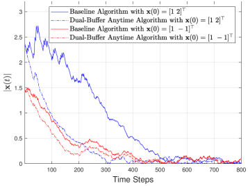
We present simulation results of the proposed dual-buffer anytime control algorithm and the baseline single-buffer algorithm [10], where the S-C and C-A channels are modeled as multi-state Markov chains. The system parameters are the same as in the numerical example in Section III. We consider an open-loop unstable constrained plant model of (53) in the presence of noise [11]:
| (55) |
where
| (56) |
and the process noise and are independent zero-mean i.i.d. Gaussian and . We take the control policy as .
In Fig. 4, we show the simulation of with time steps for both the dual-buffer anytime method and the baseline method. It is clear that the dual-buffer method significantly outperforms the baseline especially when the initial process state is far from the origin. Therefore, adding the command buffer at the actuator can effectively overcome the effect of packet dropouts, leading to significant control performance improvement.
VI Conclusions
We have studied an anytime control algorithm for dual-channel-dual-buffer WNCS with random computational resources over correlated channels. We have proposed a novel approach to derive sufficient conditions for stochastic stability in the case of nonlinear plant models with disturbances. The stability conditions are stated in terms of plant dynamics, network dynamics, buffer properties and computational resource dynamics. Our numerical results have shown that the proposed dual-buffer anytime control system can provide significant control performance improvement when compared to the conventional single-buffer system as it effectively overcomes the effect of packet dropouts. In future work, we will consider optimal control sequence design. In addition, we may include an extension to large-scale WNCSs with multiple plants and controllers and that need to share network and communication resources.
References
- [1] L. K. McGovern and E. Feron, “Requirements and hard computational bounds for real-time optimization in safety-critical control systems,” in Proc. IEEE CDC, 1998, pp. 3366–3371.
- [2] ——, “Closed-loop stability of systems driven by real-time, dynamic optimization algorithms,” in Proc. IEEE CDC, 1999, pp. 3690–3696.
- [3] D. Henriksson, A. Cervin, J. Akesson, and K. . Arzen, “On dynamic real-time scheduling of model predictive controllers,” in Proc. IEEE CDC, 2002, pp. 1325–1330.
- [4] A. Cervin, M. Velasco, P. Marti, and A. Camacho, “Optimal online sampling period assignment: Theory and experiments,” IEEE Trans. Control Syst. Technol., vol. 19, no. 4, pp. 902–910, 2011.
- [5] P. Tabuada, “Event-triggered real-time scheduling of stabilizing control tasks,” IEEE Trans. Autom. Control, vol. 52, no. 9, pp. 1680–1685, 2007.
- [6] X. Wang and M. D. Lemmon, “Self-triggered feedback control systems with finite-gain stability,” IEEE Trans. Autom. Control, vol. 54, no. 3, pp. 452–467, 2009.
- [7] R. Bhattacharya and G. J. Balas, “Anytime control algorithm: Model reduction approach,” J. Guidance, Control, Dynamics, vol. 27, no. 5, pp. 767–776, Sep.-Oct. 2004.
- [8] V. Gupta and F. Luo, “On a control algorithm for time-varying processor availability,” IEEE Trans. Autom. Control, vol. 58, no. 3, pp. 743–748, 2013.
- [9] D. E. Quevedo and V. Gupta, “Sequence-based anytime control,” IEEE Trans. Autom. Control, vol. 58, no. 2, pp. 377–390, 2013.
- [10] D. E. Quevedo, W.-J. Ma, and V. Gupta, “Anytime control using input sequences with Markovian processor availability,” IEEE Trans. Autom. Control, vol. 60, no. 2, pp. 515–521, Feb. 2015. [Online]. Available: https://arxiv.org/pdf/1405.0751.pdf
- [11] D. E. Quevedo, V. Gupta, W. Ma, and S. Yüksel, “Stochastic stability of event-triggered anytime control,” IEEE Trans. Autom. Control, vol. 59, no. 12, pp. 3373–3379, 2014.
- [12] T. V. Dang, K. Ling, and D. E. Quevedo, “Stability analysis of event-triggered anytime control with multiple control laws,” IEEE Trans. Autom. Control, vol. 64, no. 1, pp. 420–426, 2019.
- [13] X.-S. Zhan, J. Wu, T. Jiang, and X.-W. Jiang, “Optimal performance of networked control systems under the packet dropouts and channel noise,” ISA Transactions, vol. 58, pp. 214–221, 2015. [Online]. Available: https://www.sciencedirect.com/science/article/pii/S0019057815001299
- [14] P. Sadeghi, R. A. Kennedy, P. B. Rapajic, and R. Shams, “Finite-state Markov modeling of fading channels - a survey of principles and applications,” IEEE Signal Process. Mag., vol. 25, no. 5, pp. 57–80, Sep. 2008.
- [15] K. Huang, W. Liu, Y. Li, B. Vucetic, and A. Savkin, “Optimal downlink-uplink scheduling of wireless networked control for Industrial IoT,” IEEE Internet Things J., vol. 7, no. 3, pp. 1756–1772, Mar. 2020.
- [16] K. Huang, W. Liu, Y. Li, and B. Vucetic, “To retransmit or not: Real-time remote estimation in wireless networked control,” in Proc. IEEE ICC, May 2019, pp. 1–7.
- [17] K. Huang, W. Liu, M. Shirvanimoghaddam, Y. Li, and B. Vucetic, “Real-time remote estimation with hybrid ARQ in wireless networked control,” IEEE Trans. Wireless Commun., vol. 19, no. 5, pp. 3490–3504, 2020.
- [18] D. Tse and P. Viswanath, Fundamentals of wireless communication. Cambridge university press, 2005.
- [19] Y. Polyanskiy, H. V. Poor, and S. Verdu, “Channel coding rate in the finite blocklength regime,” IEEE Trans. Inf. Theory, vol. 56, no. 5, pp. 2307–2359, May 2010.
- [20] A. J. Goldsmith and Soon-Ghee Chua, “Variable-rate variable-power mqam for fading channels,” IEEE Trans. Commun., vol. 45, no. 10, pp. 1218–1230, 1997.
- [21] L. Schenato, B. Sinopoli, M. Franceschetti, K. Poolla, and S. S. Sastry, “Foundations of control and estimation over lossy networks,” Proc. IEEE, vol. 95, no. 1, pp. 163–187, Jan. 2007.
- [22] D. E. Quevedo and D. Nešić, “Robust stability of packetized predictive control of nonlinear systems with disturbances and markovian packet losses,” Automatica, vol. 48, no. 8, pp. 1803 – 1811, 2012.
- [23] W. Liu, D. E. Quevedo, Y. Li, K. H. Johansson, and B. Vucetic, “Remote state estimation with smart sensors over markov fading channels,” submitted to IEEE Trans. Autom. Control, 2020. [Online]. Available: https://arxiv.org/abs/2005.07871
- [24] W. Liu, D. E. Quevedo, K. H. Johansson, Y. Li, and B. Vucetic, “Remote state estimation of multiple systems over multiple markov fading channels,” submitted to IEEE Trans. Autom. Control, 2021. [Online]. Available: https://arxiv.org/abs/2104.04181
- [25] R. Durrett, Probability: Theory and Examples. Cambridge university press, 2019, vol. 49.
- [26] W. Liu, D. E. Quevedo, Y. Li, and B. Vucetic, “Anytime control under practical communication model,” submitted to IEEE Trans. Autom. Control, 2021. [Online]. Available: https://arxiv.org/abs/2012.00962
- [27] H. Minc, Nonnegative Matrices. Wiley, 1988.
- [28] State Transition Matrix of , May 2021. [Online]. Available: {https://drive.google.com/file/d/12hnTfMwKoM9Rx4eXSlq9N0Sak_6M8dtb/view?usp=sharing/}
- [29] O. L. V. Costa, M. D. Fragoso, and R. P. Marques, Discrete-time Markov jump linear systems. Springer Science & Business Media, 2006.
A. Proof of Lemma 5
Direct calculations give that
| (57) | ||||
where and
| (58) |
From (58), we define such that , i.e.,
| (59) |
where and .
B. Proof of Theorem 3
The proof follows the same steps of [10, Theorem 7.1] in analyzing the noise effect on the performance, since the analysis only depends on the process . From [10], it can be obtained that
| (69) | ||||
where is defined in (34), , , and and are bounded constant determined by , , , , , , and (see [10, Appendix D] for the calculation of and ).