As-Continuous-As-Possible Extrusion Fabrication of Surface Models
Abstract.
We propose a novel computational framework for optimizing the toolpath continuity in fabricating surface models on an extrusion-based 3D printer. Toolpath continuity has been a critical issue for extrusion-based fabrications that affects both quality and efficiency. Transfer moves cause non-smooth or bumpy surfaces and get worse for materials with large inertia like clay. For surface models, the effects of continuity are even more severe, in terms of surface quality and model stability. In this paper, we introduce an original criterion “one-path-patch” (OPP), for representing a shell surface patch that can be traversed in one path considering fabrication constraints. We study the properties of an OPP and the merging operations for OPPs, and propose a bottom-up OPP merging procedure for decomposing the given shell surface into a minimal number of OPPs and generating the ”as-continuous-as-possible” (ACAP) toolpath. Furthermore, we customize the path planning algorithm with a curved layer printing scheme, which reduces the staircase defect and improves the toolpath continuity via possibly connecting multiple segments. We evaluate the ACAP algorithm for both ceramic and thermoplastic materials, and results demonstrate that it improves the fabrication of surface models in both surface quality and efficiency.
1. Introduction
Surface or shell models are widely used in structural design, being efficient in shape presentation and possessing featured functionalities like lightweight and effective thermal conductivity. Potteries in the shell form have been developed since the Stone Age. In the context of additive manufacturing (AM), shells are cost-effective for both materials and fabrication time compared to solid ones. In this paper, we focus on the surface model, particularly a thin shell with the thickness of a single path. It can be either open or closed, and therefore segments exist in layers for open surface models.
Continuity of the toolpath is one of the most fundamental problems in material extrusion-based AM. Continuity of the nozzle’s movement and material extrusion directly affects the surface quality, model stability, and fabrication efficiency. For extrusion fabrication of surface models, the toolpath continuity plays a more critical role than solid models. Besides the surface quality and printing efficiency, transfer moves induce extra forces to the printed shell surface, weakening the stability, and the model may sag or collapse along with the accumulation of the forces.
Especially, fabricating surface models with clay is getting popular thanks to the rapid progress on the ceramics printing techniques. The most feasible and cost-effective technique for 3D printing clay is direct ink writing (DIW), which shares the same architecture with fused deposition modeling (FDM), but has a larger opening nozzle that provides more material extrusion efficiency for high viscosity clay than thermoplastics [Chen et al., 2019b]. As a natural material, clay is environmentally friendly and durable. Since the deposition rate of semi-liquid pastes is large, surface models are the most popular 3D printed objects. Nevertheless, the artifacts on the surface quality caused by transfer moves cannot be negligible.
Existing path planning methods can be grouped into two broad categories. One group focuses on optimizing the infilling patterns in each layer section [Zhao et al., 2016; Zhai and Chen, 2019] and achieves the continuous toolpath even in the layer with complicated contours; however, surface models with no interiors cannot take the advantage. The other group is applicable to surface models, optimizing the sequences of contours [Lensgraf and Mettu, 2017, 2018; Yoo et al., 2020] based on search algorithms to achieve the minimal ”extrusionless travel distance.” Nevertheless, this wasted motion criterion is not equivalent to the toolpath continuity in terms of the number of transfer moves. The optimal continuous toolpath of a surface model is essentially a tailored surface decomposition problem considering the fabrication constraints.
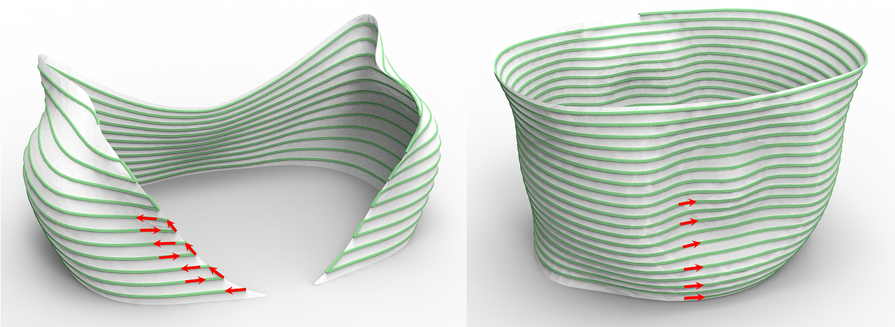
Hergel et al. [2019] recently proposed a path planning method for extrusion-based ceramics printing, which produces strictly continuous deposition paths that eliminate transfer moves. This method works well with a single contour for each layer but cannot print multiple components per layer without adding non-model structures. Therefore, it cannot be easily adopted for shell models, as ”hiding” the non-model intermediate structures without affecting the surface appearance is almost impossible, especially for open surfaces, referring to Figure 2.
Curved layers manufacturing is regarded as an effective method for removing the staircase defects [Etienne et al., 2019] and improving the strength through aligning filaments along the directions with large stresses [Fang et al., 2020]. For surface models, curved layers have unique advantages that multiple components may be printed in a connected toolpath.
Adopting the curved layers scheme for Cartesian 3D printing faces two more constraints from fabrication besides continuity. First, the layer thickness is adjustable but bounded by the extrusion amount. Second, the slope of the curved toolpath cannot be too steep, as the collision between the nozzle and printed model must be considered. Considering the fabrication constraints, the problem can be regarded as a Precedence Constrained Minimum Path Cover Problem (PC-MPC) , which is equivalent to a classical NP-hard problem PC-TSP (see more details in Appendix A).
We target producing the “as-continuous-as-possible” (ACAP) toolpath for surface models, such that the number of transfer moves is minimized. Our key idea is to propose a “one-path-patch” (OPP) criterion to represent a surface patch that can be printed in a continuous toolpath, in combined flat and curved layers. We propose a bottom-up OPP merging algorithm for decomposing the given shell model into a minimal number of OPPs and generate the ACAP toolpath. This paper makes the following contributions:
-
•
we introduce an original, fabrication constraints-aware, criterion “one-path-patch” (OPP) for representing a shell surface patch that can be printed in one path in the context of both flat layer and curved layer printing scheme.
-
•
we propose a novel algorithm for decomposing the given shell surface into a minimal number of OPPs and generating the “as-continuous-as-possible” (ACAP) collision-free toolpath.
-
•
we adapt our technique as a general computation framework for printing shell models in a “as-continuous-as-possible” manner on 3-axis extrusion-based printing platforms.
2. Related Work
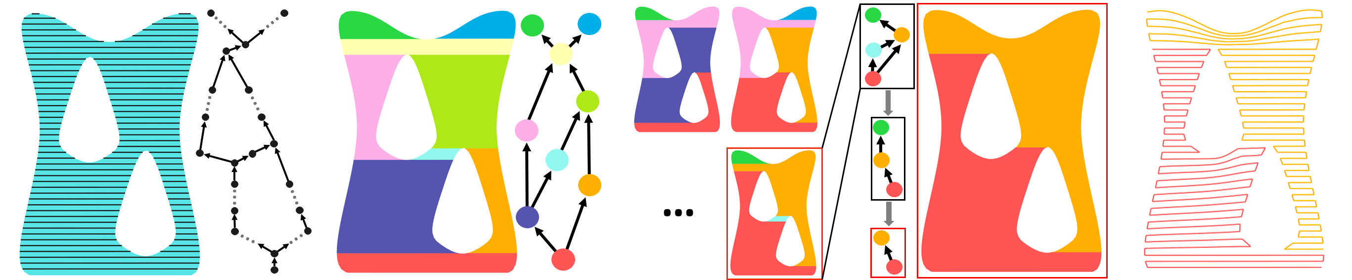
(a) Dependency relationship (b) Initial decomposition (c) Merging with flat layers (d) Merging with curved layers (e) Toolpath generation
Slicing and Path Planning
In AM, the slicer is used for converting a model to toolpaths. Existing slicing algorithms divide the model as a stack of flat layers by geometric operations. [Lensgraf and Mettu, 2016, 2017, 2018; Yoo et al., 2020] proposed a series of optimization algorithms to minimize the total extrusionless travel distance (wasted motion or print time) in the space of feasible toolpaths. We represent the precedence constraints as the dependency graph in a similar manner. In contrast, we define the OPP criterion, reform the optimization in a more compact dependency graph, and gain a more efficient optimization framework. For most cases, we can achieve the optimal results rather than approximated ones. Many efforts have been made to optimize the toolpath in terms of continuity, filling rates, and mechanical properties [Zhao et al., 2016; Zhai and Chen, 2019; Xia et al., 2020]. Adaptive bead width control could further reduce the under- and over-filling artifacts [Kuipers et al., 2020; Hornus et al., 2020]. Hergel et al.[2019] present a method for generating strictly-continuous, self-supporting deposition paths for extrusion-based ceramic printing, performing nicely on watertight geometric models. However, this method cannot directly apply to shell models as illustrated in Figure 2.
Curved Layers Printing
Compared with traditional flat layers, curved layers contain dynamic z-values within individual layers and have excellent properties in AM. Such as alleviating the staircase defect, improving surface smoothness, strengthening the printing model and reducing printing time. The first discussion about curved layers is called curved layers fused deposition modeling (CLFDM) [Chakraborty et al., 2008], which allows continuous change of the z-value within individual layers. Afterwards, [B.Huang and S.Singamneni, 2012; Allen and Trask, 2015; Llewellyn-Jones et al., 2016] perform physical experiments with FDM printers to demonstrate these properties. The industry standard slicing software Ultimaker Cura [Ultimaker, 2021] also involves the curved layer printing in the surface mode that produces spiralized outer contours of the mesh instead of the solid model, which works well on simple shapes like a vase or cylinder. [Ezair et al., 2018] present an algorithm that generates covering curves based on geometric characteristics of a given volume. [Etienne et al., 2019] take a different approach that optimizes a parameterization to obtain smooth surface tops. The produced toolpaths are mapped back into the initial domain without requiring splitting or re-ordering. We apply this method in our curved OPP merging. Recently, researchers have applied curved layers printing on multi-axis printers. With the help of additional DOF, [Dai et al., 2018; Xu et al., 2019; Li et al., 2021] design curved toolpath to fabricate solid models in a support-free way. [Chen et al., 2019a] present a new CLFDM slicing algorithm that allows variable thickness layers. [Fang et al., 2020] introduce a field-based optimization framework to generate curved layers for reinforcing the mechanical strength of 3D printed models. However, we focus on three-axis printer platforms in this paper.
Fabrication of Thin Shells
Fabricating thin shells is gaining increasing attention as it accelerates the fabrication time compared to closed models and lightweight shell models are of wide applications. This advantage is further enhanced when fabricating viscous slurry materials, like clay and concrete, with large extrusion amount and fast deposition rate. For shell models, the continuity of material deposition is more critical due to the apparent artifacts caused by transfer moves. Most works in the literature adopt multi-axis platforms and incorporate curved layers for printing shells. [Mitropoulou et al., 2020] present a method to design non-planar layered print paths for robotic FDM printing of single-shell surfaces. [Bhatt et al., 2020] propose the layer slicing and toolpath planning algorithm to build thin shell parts on a 3-DOF build-platform and a 3-DOF extrusion tool. Printing concrete shells is attracting interests in the interdisciplinary area of digital fabrication and architecture. [Burger et al., 2020] use the single-shell as molds for concrete casting. [Anton et al., 2019] propose a design tool for producing bespoke concrete columns and involve curved layer for continuous extrusion. [Bhooshan et al., 2020] also emphasize on interactively shell modeling and integrate modeling with toolpath generation.
Decomposition for Fabrication
Many efforts have been focused on model decomposition for fabrication. Objectives for model decomposition include fabricating the model that satisfy the constraint, improving surface quality, saving or avoiding support structures, and reducing printing time. [Luo et al., 2012] propose a solution to decompose the model into smaller parts that every part can fit the printing platform. In addition to considering the criterion of printing volume, structural soundness and aesthetics are their decomposition objectives. For improving surface quality, [Hildebrand et al., 2013] generate a partition and compute the optimal slicing direction for subparts. [Hu et al., 2014] decompose a given shape into as few approximate pyramidal parts as possible. Their motivation is that pyramidal shapes are well suitable for fabrication. [Vanek et al., 2014; Wei et al., 2018] decompose shell models into small parts to save the support material and reduce the printing time. A manual assembly process is required after printing all shells. Also, to avoid supporting materials, [Wu et al., 2017, 2020]’s decomposition approaches consider the collision-free constraint and sequence of printing. They printed models in a multi-DOF 3D printing system so that manual assembly is not required. [Herholz et al., 2015; Muntoni et al., 2018] decompose general three-dimensional geometries to satisfy the height field constraint. To minimize the number of cutter setups for finish-stage machining in CNC, [Zhao et al., 2018] develop an algorithm to perform surface decomposition with the accessibility constraint. The above methods did not consider the continuity of the printing path as a criterion for model decomposition. It is worth mentioning that [Mahdavi-Amiri et al., 2020] propose carvability criteria for continually carving a connected domain, which requires both visibility and monotonicity. However, they did not take curved slicing layers into account. In such situation, the key difference between our OPP criterion and carvability is that OPP does not require visibility but support curved layering fabrication.
Ceramic Printing
Ceramic materials in AM have attracted heightened attention in recent years [Zocca et al., 2015; Chen et al., 2019b]. It would reduce both processes and resources required to produce geometrically complex shapes in the traditional ceramics industry, and thus nurture new ideas or applications in architectural decorations [Chan et al., 2020], arts, etc. Researchers are also developing advanced engineering ceramics, such as metal oxides, carbides, and nitrides, to specific engineering demands [Peng et al., 2018]. Existing work mainly focuses on studying formulations of the water-to-clay ratios and some additives, and physical analysis of the sintered models in terms of compression, thermal stability, etc. [Revelo and Colorado, 2018; Ordoñez et al., 2019].
Even though the slicing and toolpath planning for DIW ceramic printing share both constraints and objectives with FDM, it possesses additional constraints due to the viscosity of clay, which is attracting the attention of researchers. Recent attempts consider the path planning for closed model [Hergel et al., 2019], integrated modeling and path generation for relatively simple shapes [Zhong et al., 2020], and stability enhancement for shell models [Xing et al., 2021]. While for general shell models, there are still no effective path planning methods.
3. Overview
Given a thin shell model with a feasible orientation that meets the support structure constraint, our algorithm aims to achieve maximal path continuity, i.e., decompose into a minimum number of surface patches where each patch can be printed consecutively. For narrative convenience, in this paper we define a printable surface patch as a patch that can be printed with a single path.
As a PC-MPC problem, such decomposition is NP-hard that no efficient solution on all possible inputs. Our key idea is to apply an over-segmentation followed by a bottom-up merging procedure. We first slice through uniformly distributed flat planers (subsection 4.1). Each sliced element can be seen as a single printable surface patch. Multiple printing paths from mutually contiguous sliced elements can be connected into a single path by including a set of short connecting paths, which indicates that we can reduce the number of printable patches via merging small initial patches (subsection 4.2). Besides, we observe that curved slicing layers can be exceptionally effective in generating continuous printing paths for multiple separate printable surface patches of flat layers. The number of printable patches can be further reduced by replacing flat layers with curved slicing layers as much as possible (subsection 4.3).
The merging criterion is the main challenge for the bottom-up merging and curved layers replacement process. We need to formulate the ”sub-surface-patches” that can be merged into a single printable patch or replaced by curved layers. The new concept of ”one-path-patch” (OPP) is introduced as the merging criterion (subsection 3.2). As a final step, we carry out the path planning for each OPP, followed by a post-optimization process to improve the path smoothness and spacing (subsection 4.4). Note that we avoid the potential global collision between the printer and printed layers considering the nozzle size (section 5). Our algorithm pipeline is illustrated in Figure 3.
3.1. Fabrication Constraints
We mainly consider three fabrication constraints in this work. The first bounds a feasible range of layer thickness. The second is to avoid collision between the extrusion device (nozzle, extruder, and carriage) and the printed parts while operating toolpath from curved layers. The third describes the geometric requirement for the decoupling fabrication strategy of the intact model and support structures.
Thickness constraint
![[Uncaptioned image]](https://cdn.awesomepapers.org/papers/340228cd-859d-44d6-82b2-7a5b7654e2be/thickness1.png)
Affected by the fluidity of materials, too small layer thickness would cause the layers to squeeze together. Such an over-stacking effect results in artifacts on the surface (see inset). While too large thickness results in under-stacking, the adjacent layers are not well bonded. We use and to represent the minimum and maximum layer thickness. For ceramic printing, we take and . For FDM printing, and . This range is used as a constraint when generating the curved layers.
Slope angle constraint
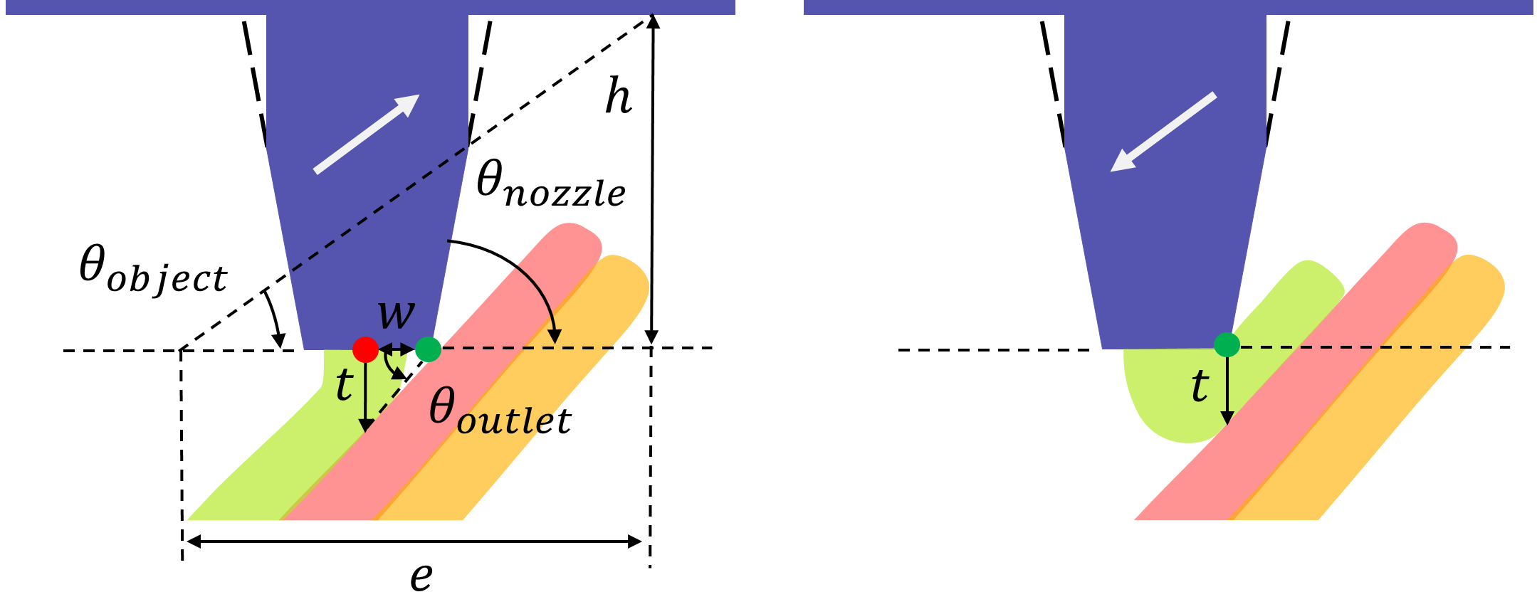
In [Etienne et al., 2019], the collision constraint has been modeled as an inverted cone to forbid already printed parts from entering. A local slope angle constraint for the printing paths is extracted from the forbidden cone as (see Figure 4 for the detailed formulation). Instead of regarding the printer as a pointed conical nozzle by overlooking the nozzle part’s flat outlet, we propose making this formulation more precise. We represent the nozzle as a combination of a cylinder and a truncated cone.
We make an interesting observation that the possible collision differently when going uphill and downhill. See Figure 4, when going uphill (left), since the point on the right side of the outlet (green dot) is closest to the layer printed below, it may collide first, which can be avoided by restricting the path slope angle as . Conversely, when going downhill (right), the nozzle has to be raised by to avoid self-layer collision between the point on the right side of the outlet (green dot) and the current layer. There is no need to define any slope angle for the downhill case with the raising operation. Finally, set the upper bound of the path slope angle as . Note that this is a local constraint. The global collision caused by the height of the printed model exceeding the nozzle length is not considered. The solution will be mentioned in section 5.
Support structure constraint
We involve restrictions on the support structures for surface models, as support structures degrade the surface quality [Hergel et al., 2019]. For surface models that are not self-supporting, we decouple the fabrication of the intact model and support structures, i.e., we pre-print the support structures and place them during the fabrication process. This requires that the support structures locate on the ground and form a height field volume related to the printing orientation, as the support structures placed on the model may induce too much weight for the printed shell to afford. For such models, we decompose them into multiple patches and assemble them after fabrication (an example is shown in Figure 21).
3.2. One-Path-Patch (OPP)
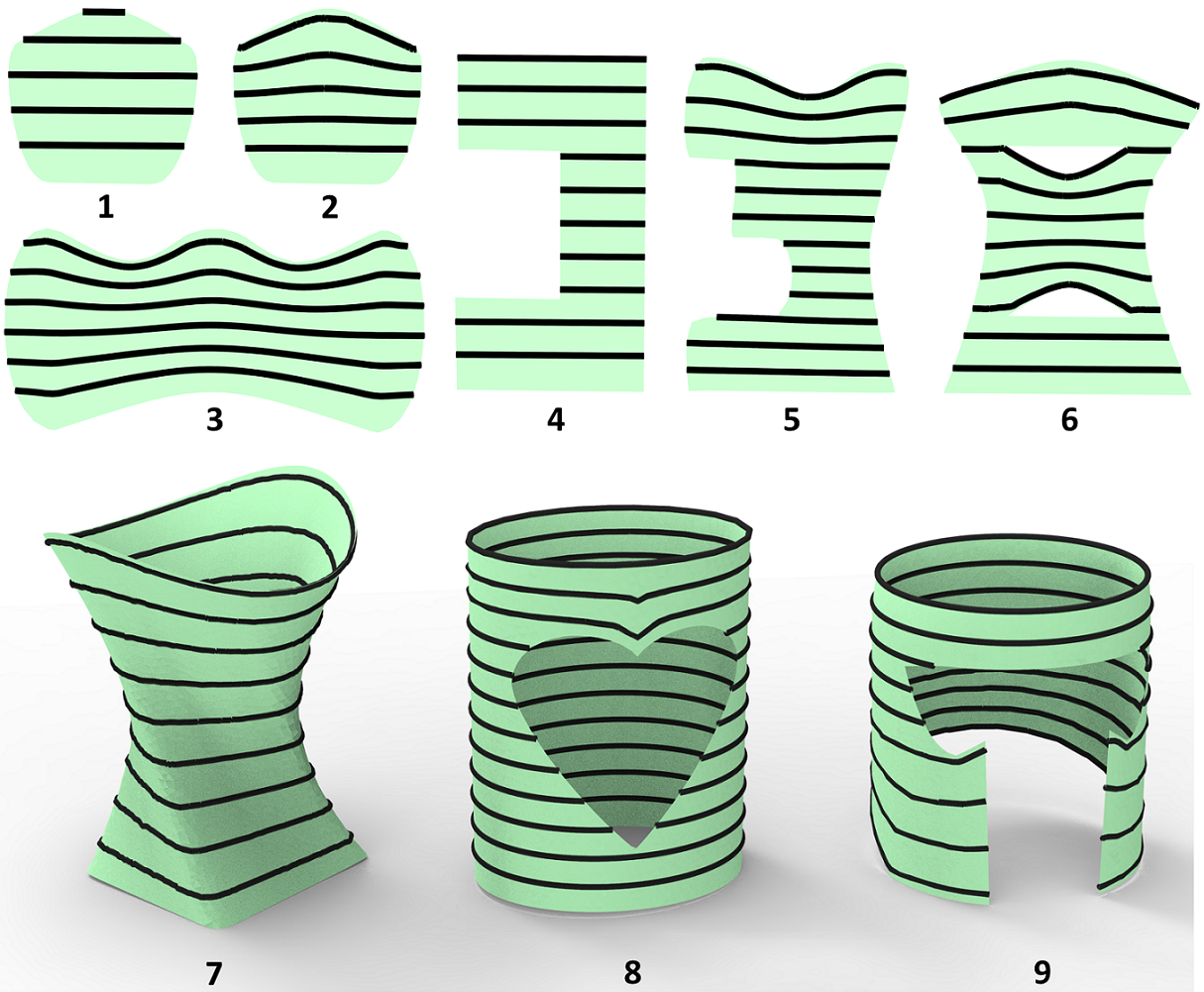
Recall that we aim to maximize the continuity by decomposing the input shell model into the minimal number of printable ”one-path-patches” (OPPs). With respect to a printing direction, a manifold surface patch is a printable OPP, iff 1) there exists a set of slicing layers where each layer orthogonal to the printing direction intersects the patch resulting in a single segment or contour; 2) the resulting intersected segments/contours satisfies the fabrication constraints. In the paper, we deliberately choose a low-resolution layer height to make the printing paths more visible. Three types of OPP can be defined according to the slicing layers: (I) only flat layers; (II) only curved layers; (III) combination of I and II, named as I-OPP, II-OPP, and III-OPP for short, shown in Figure 5. Curved layers of OPPs would take the thickness constraint and slope angle constraint.
What geometric properties should an OPP hold? For type I, the OPP criterion is equivalent to its monotonicity111A 2D polygon is monotone with respect to a straight line , if every line orthogonal to , intersects at most twice. A 3D manifold surface patch is monotone in direction if all cross-sections orthogonal to are single section [Toussaint, 1985]., as (1,4) shown in Figure 5. As for type II, the intrinsic geometric properties of an OPP is hard to propose, where monotonicity becomes a sufficient and unnecessary condition. In Figure 5, (3,5,7) is an OPP but not monotone, and it demonstrates that a single OPP with curved layers could cover regions where multiple I-OPPs are applied.
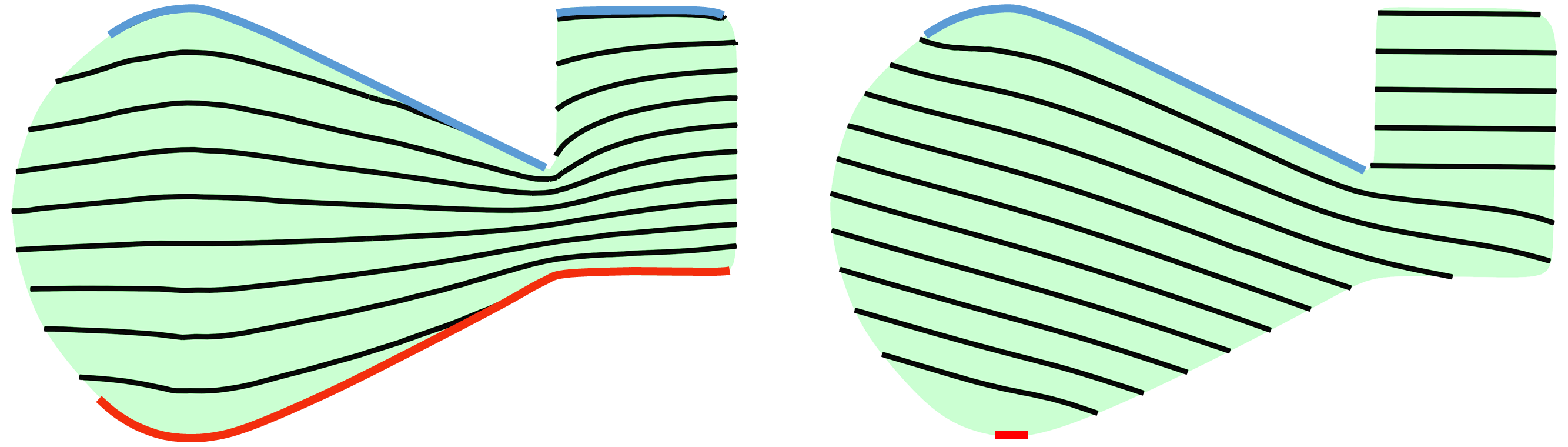
To determine whether is an II-OPP, one option can be to extract curved layers directly and then assess the two fabrication criteria. CurviSlicer seems a perfect match for this, which desires to flatten as many areas as possible to minimize staircases [Etienne et al., 2019]. However, staircase minimization is not always equivalent to continuity maximization, which is sensitive to the target flat areas taken as the input of CurviSlicer, as shown in Figure 6. Two I/II-OPPs can be merged to a single II-OPP (details in subsection 3.3). For a whole shell model, a bottom-up OPP merging procedure is introduced to minimize the number of OPPs, during which process III-OPPs (as (6,8,9) in Figure 5) are generated (subsection 4.3).
![[Uncaptioned image]](https://cdn.awesomepapers.org/papers/340228cd-859d-44d6-82b2-7a5b7654e2be/orientationDemo.png)
To the best of our knowledge, the OPP criterion has never been explored before. An OPP possesses three key properties as the elementary path generation element to maximize the continuity of extrusion-based printing:
-
(1)
The OPP criterion is defined with respect to a specific printing direction. An OPP in a printing direction (left) may not be an OPP with another direction (right), shown in the inset.
-
(2)
Even with the same printing direction, valid slicing strategies of an OPP may not be unique. In Figure 5, (1) and (2) show two kinds of slicing layers where flat and curved slicing layers can be applied. Curved layers always produce fewer staircases associated with higher priority than flat layers.
-
(3)
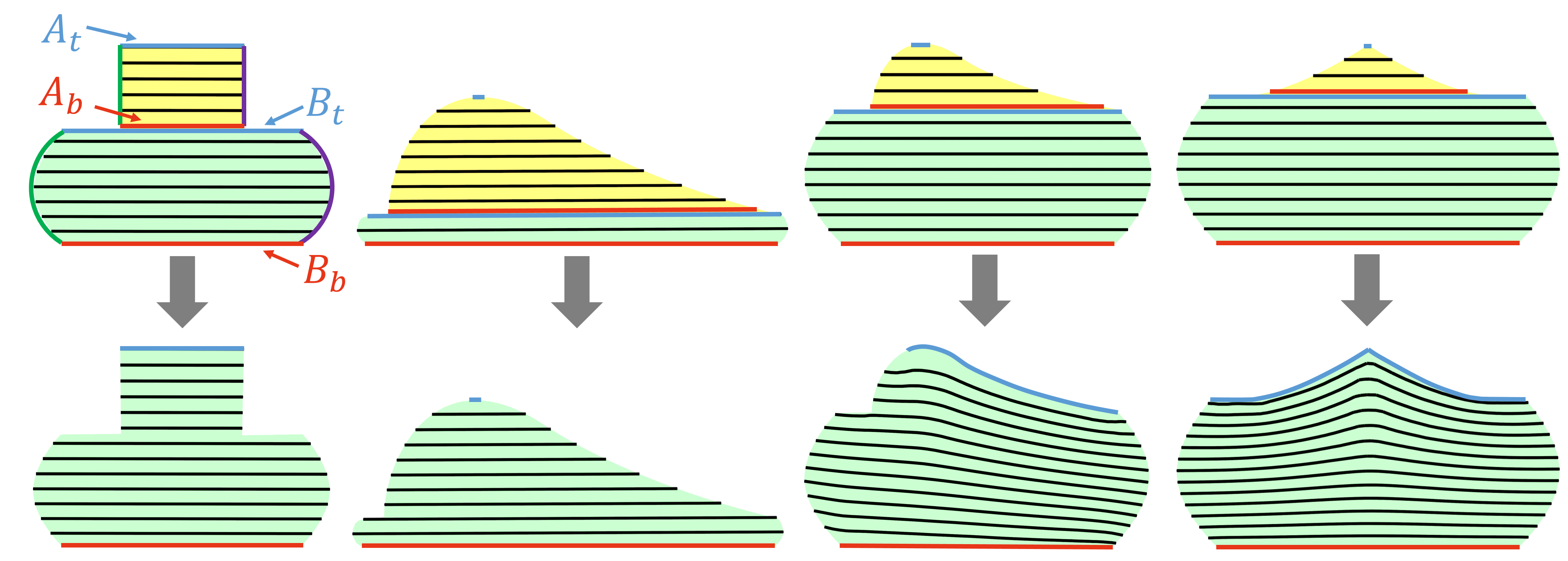
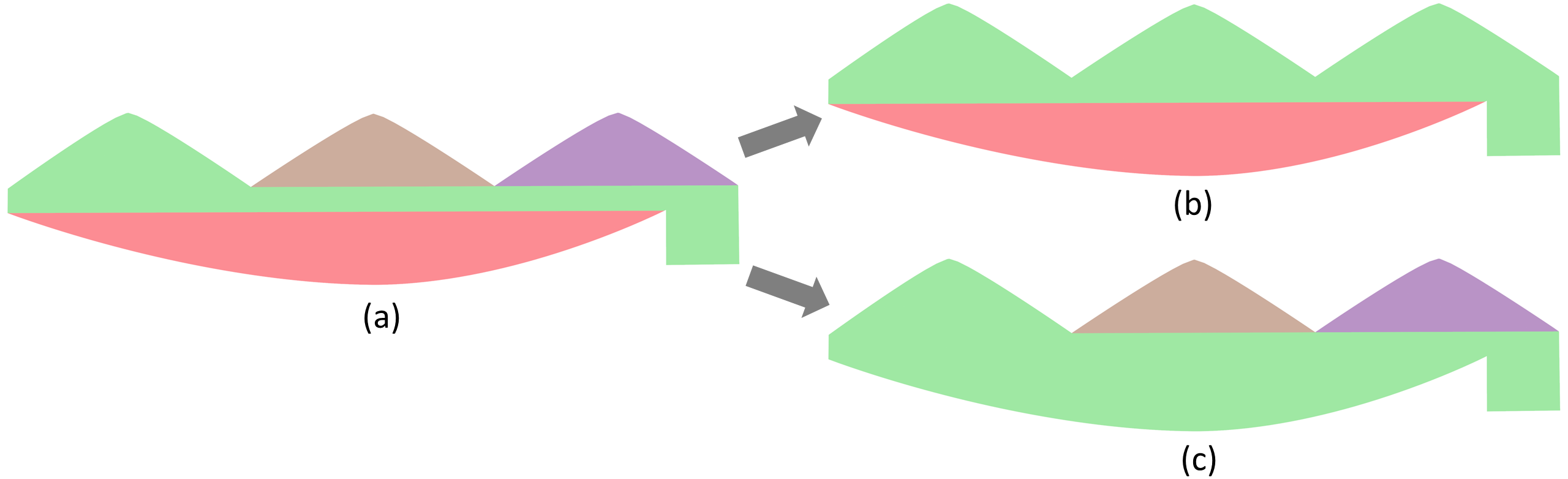
Two OPPs can be merged to one single OPP. Two OPPs (A and B) can be merged via two operations, stacking and curving, as shown in Figure 7. Stacking indicates that 1) OPP A’s bottom layer locates on the above neighboring layer of B’s top layer ; 2) and can be connected by its two end points. Curving indicates the merging operation of subsection 3.3. The two operations are used in subsection 4.3 to minimize the number of OPPs.
(a) (b) (c) (d)
3.3. Curving Operation
The input of this operation are two I/II-OPPs (A and B) that can be originally merged via stacking. Curving operation aims to output the merged OPP (C) with its slicing layers. Suppose OPP A is above over B, as shown in Figure 7. Note that curving cannot be applied for two OPPs with only closed contours.
Our basic idea is to produce a modified version of CurviSlicer to extract curved layers for the merged OPP C. There are two key questions: 1) how to determine the top/bottom target flat areas of C? 2) how to guarantee the fabrication constraints? We solve the first question by combining the top/bottom target flat areas of A and B. For the determined top/bottom target flat areas of C, detect the slope angle constraint. Then extract the in-between curved layers with our modified CurviSlicer satisfying the fabrication constraints.
For an OPP, define the projection of its top (bottom) layer as its top (bottom) target flat areas (). Starting traverse from the layer at the top layer of A, two oblique polylines can be obtained by connecting the two end points on both sides of each layer to the bottom layer. If both oblique lines violate the slope angle constraint, the two OPPs cannot be merged via curved layers. If not, we generate C’s top target flat areas by combining 1) OPP A’s top target flat areas (), 2) the difference result of B’s top target flat areas and A’s bottom target flat areas (), 3) the oblique lines that meet the slope constraint; C’s bottom target flat areas are taken from B’s bottom target flat areas.
Next, we call CurviSlicer, specifying both top and bottom target flat areas. CurviSlicer formulated two key terms in their objective: one flat term to determine whether the target area can be flattened with the slope angle and thickness constraints and one smooth term to make the generated curved layer smoother. CurviSlicer with the smooth term would be much more time-consuming, which is unnecessary for our case, since the curving operation would be called frequently, and the generated layers would not be used in the final toolpath generation. So we only use the flat term while applying CurviSlicer. The merge is executable if the top and bottom target flat areas are successfully flattened without violating the fabrication constraints. Note that CurviSlicer only works for watertight 3D models. For the surface model, we convert it to an approximate watertight model with a minimal shell thickness that can be taken as the input of CurviSlicer (details in Appendix C).
4. ACAP Methodology
This section describes our algorithm in more details. For clear exposition, we explain the methodology for open 2D patches with only segments in each layer. The extension to 3D will be discussed in section 6. As introduced in section 3, the basic idea of our algorithm is a bottom-up OPP merging process based on a unified graph-based representation of the OPP graph and a set of graph nodes merging operations for the OPP graph. The OPP graph encodes the surface decomposition and their dependencies during the bottom-up OPP merging process. The OPP node merging operations are formulated through flat and curved slicing layers.
4.1. Building Dependency Graph
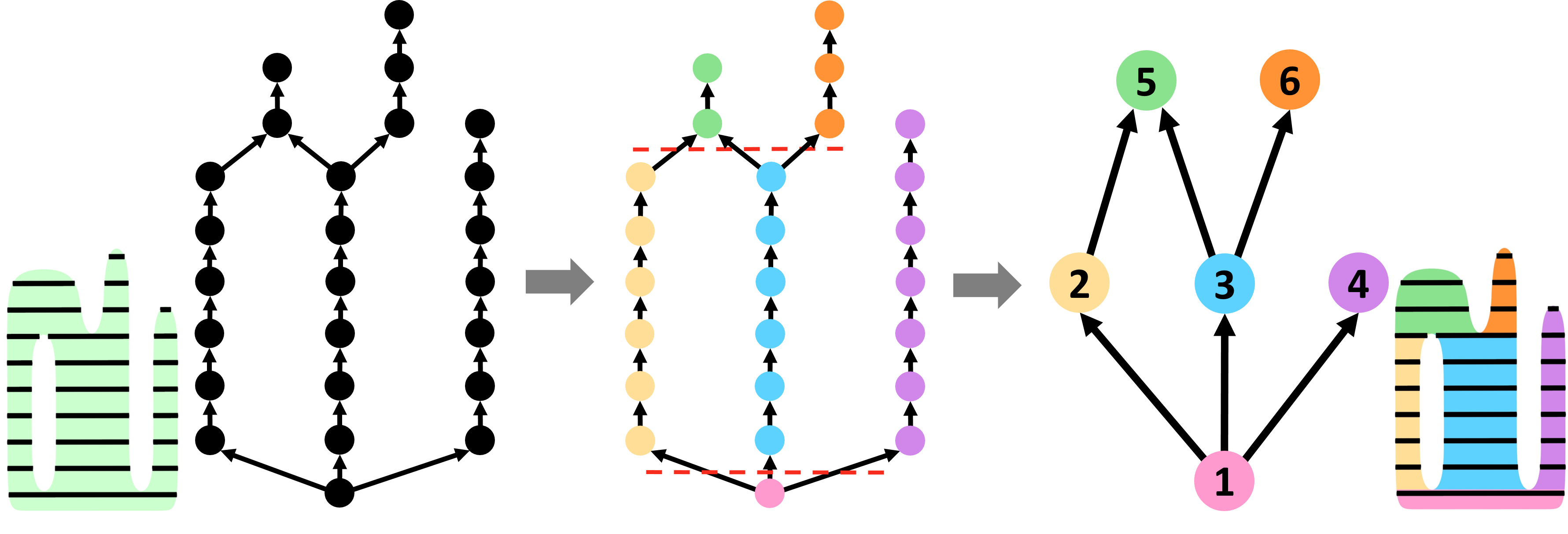
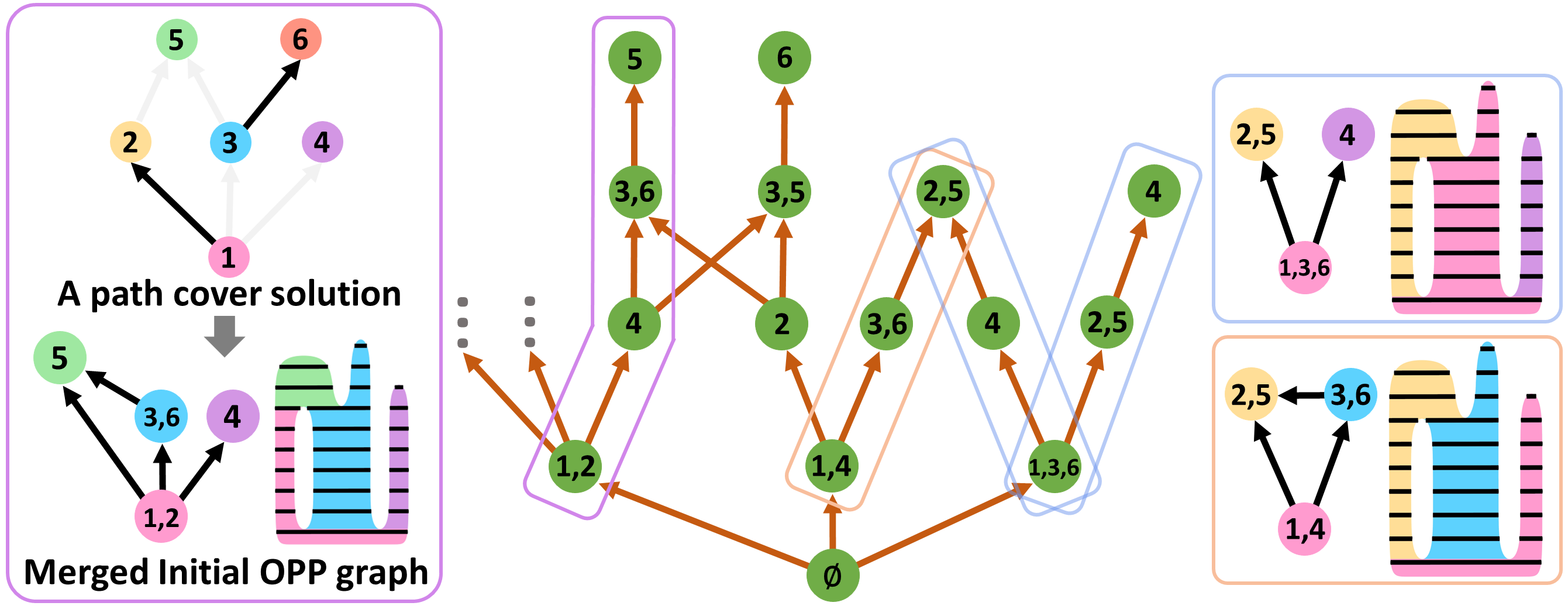
With an orientation that meets the support structure constraint (see Appendix B for details), we uniformly slice the model with flat planers vertical to the printing direction by the layer thickness (1.0mm in ceramic printing, 0.2mm in FDM), then build a directed acyclic graph to describe the dependency relationships, named dependency OPP graph , where each node represents a sliced element (segment), each directed edge represents a dependency relationship between two neighboring nodes where the closest horizontal distance between them is smaller than the path width (6.0mm in ceramic printing, 1.5mm in FDM), shown in Figure 8(a). If node has a directed edge pointing to , it indicates that (1) can only be printed only after and (2) the two OPP nodes can be merged through stacking operation. A node can be printed only if all nodes it depends on have been printed.
4.2. OPP Merging through Flat Layers
This section aims at maximal continuity provided by flat slicing, that is, merging the flat sliced elements of to a minimal number of I-OPPs. Each sliced element can be seen as an I-OPP, which can be merged by stacking operation (subsection 3.2). The merged I-OPPs should keep the dependency relationships formulated in . Such merging process is indeed to find a path cover for with the fewest paths considering the dependency relationships.
We propose two key steps for the merging process: 1) merge the nodes of that must appear on the same path in any minimum path cover in advance, then build an initial OPP graph to reduce the size of . 2) merge the nodes of further by solving the path cover problem with the dependency constraints. Rather than running an approximation algorithm, we propose a searching-based method with a pruning strategy to explore the possible solutions.
Initial OPP Graph
To build a simplified graph from , we traverse all nodes of , if there are two or more edges pointing to the same node or starting from the same node, delete these edges temporarily (crossed by dashed red lines in Figure 8(b)). Then compute the connected components. Each component acts as a node of , which can be seen as a merged larger I-OPP by stacking. Such a merging process maintains the optimality, i.e., the sub-nodes of a node must belong to a single path of the optimal solution222This can be proved using proof by contradiction. If two adjacent sub-nodes belong to the two paths of an optimal solution, they must be terminal nodes of the paths. Obviously, the two paths can be further connected, which shows that the current path cover solution is not optimal. . The dependencies of are inherited from . As shown in Figure 8(c), the nodes are significantly reduced.
(a) (b) (c)
(a) (b) (c)
Path Cover of Initial OPP Graph
OPP nodes of can be further merged via stacking, as (1,2), (1,3,6), (3,5) in Figure 8(c). A merged flat OPP graph of can be generated as a result of a path cover solution of , where each path proposes a merged I-OPP. Each node of merged OPP comprises a sequence of I/II-OPPs (denoted as sub-OPPs), where the sequence edges indicate the printing order. Figure 9(a) shows a merged with four merged I-OPPs based on the path cover solution {(1,2), (4), (3,6), (5)}. Note that the dependency relationships of are preserved. Such path cover solution can be generated from a specific Depth First Search (DFS) starting from the root nodes of . Different from a general DFS, it may not explore as deep as possible to the unexplored node before backtracking. The search has to stop while a node’s dependent nodes have not been explored, such as (1,2,5) is not valid that (3) is not explored.
The path cover solution space of can be represented by a specific directed graph structure (), where the root node is set to an empty node (an additional virtual node), the non-root nodes indicate the corresponding merged I-OPPs of path cover solutions, the directed edges encode the printing order of merged I-OPPs. A path cover solution is presented as a finite sequence of directed edges and nodes of starting from its root node, (see the sequence of in Figure 9(b)).
Path Cover Solution Space Exploration
To merge into the minimal number of I-OPPs, we aim to search for the shortest sequences while exploring . We propose two key techniques to speed up such exploration by pruning the solution space. First, starting from the root node of , we apply a beam search procedure with the branch and bound technique, to explore level by level, where the beam search width is set to in our implementation. For each level of , we sort its candidate nodes by the number of included ’s nodes, which implies that we tend to pick the nodes of including ’s nodes as many as possible. Note that nodes of would point to the same node of next level if its sequence included ’s nodes remain the same, such as {(1,2), (4)} and {(1,4), (2)} both point to (3,6) and (3,5). Second, for generating candidate nodes of each beam search iteration, we use a greedy strategy in the path cover solution generation with DFS, that each traversal would explore as deep as possible, as the traversal (1,3) will not terminate at node (3) since node (6) can be added into (1,3,6) shown in Figure 8(c). We have proved the optimality of this strategy333In the traversal path process, if terminating the path when a node can be added, the node must be the starting point of another path. In the same way as the last proof, the number of paths of path cover, in this case, is at least 1 more than our strategy, so it is not optimal.. The proposed path cover exploration method would produce multiple optimal with the least number of OPP nodes shown in Figure 9(c). The pseudo-code is presented in Appendix E.
4.3. OPP Merging through Curved Layers
Up to now, we obtained a set of unique with the maximal continuity via flat slicing. Could we further merge its OPP nodes? Recall that we observe curved slicing layers can be exceptionally effective in generating continuous printing paths for multiple separate printable surface patches of flat layers. Driven by this insight, we apply the curving operation (defined in subsection 3.3) as much as possible to further reduce number of OPPs. This can be done in two steps. First, apply the curving operation to sub-OPPs of each OPP node (Initial Merging Process), which would enlarge the target flat areas to be beneficial to the subsequent OPPs merging process. Second, apply the curving operation to merge multiple OPPs (OPP Merging Process). Below we propose a general pairwise-based merging procedure for both initial and OPP merging processes. We set as an initial curved OPP graph , iteratively merge to implement the two merging processes. II-OPPs and III-OPPs would be generated accordingly.
General Pairwise Merging Procedure
OPP graphs are directed acyclic graphs (DAG). We propose an iteratively pair-wise merging procedure for a general DAG. For each iteration, randomly select an edge and try to merge the two related nodes with specific merging criteria to check whether they can be merged or not. If yes, update the graph by 1) erasing the edges of the two nodes, 2) merging a pair of nodes to one node and 3) connecting other related edges of the two nodes to the merged node. The terminal condition is that no pairs of nodes can be merged.
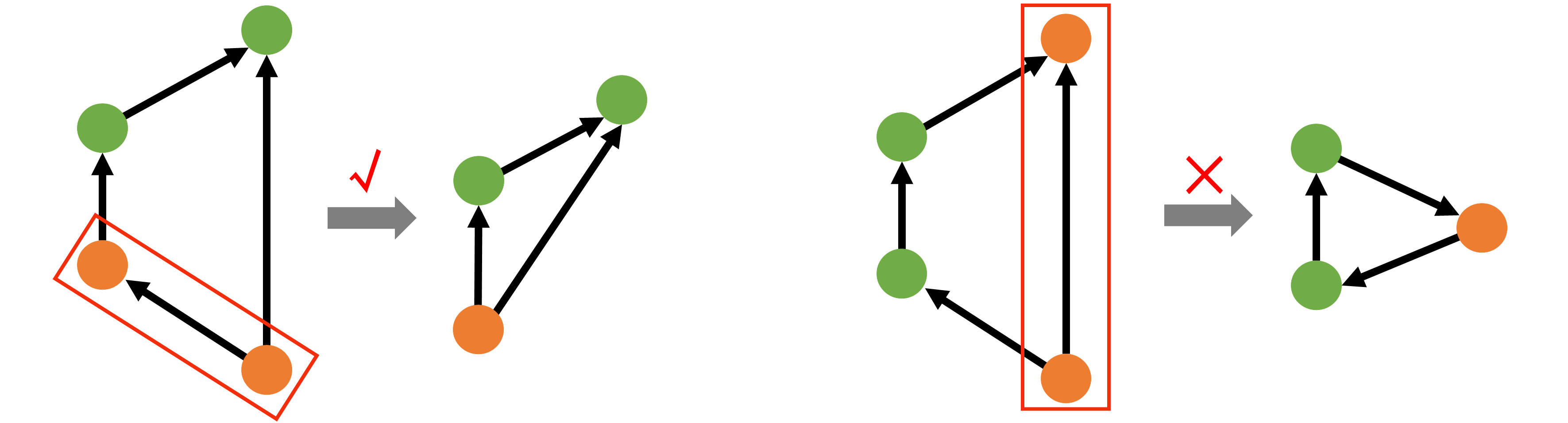
Merging Criteria of OPP Graph
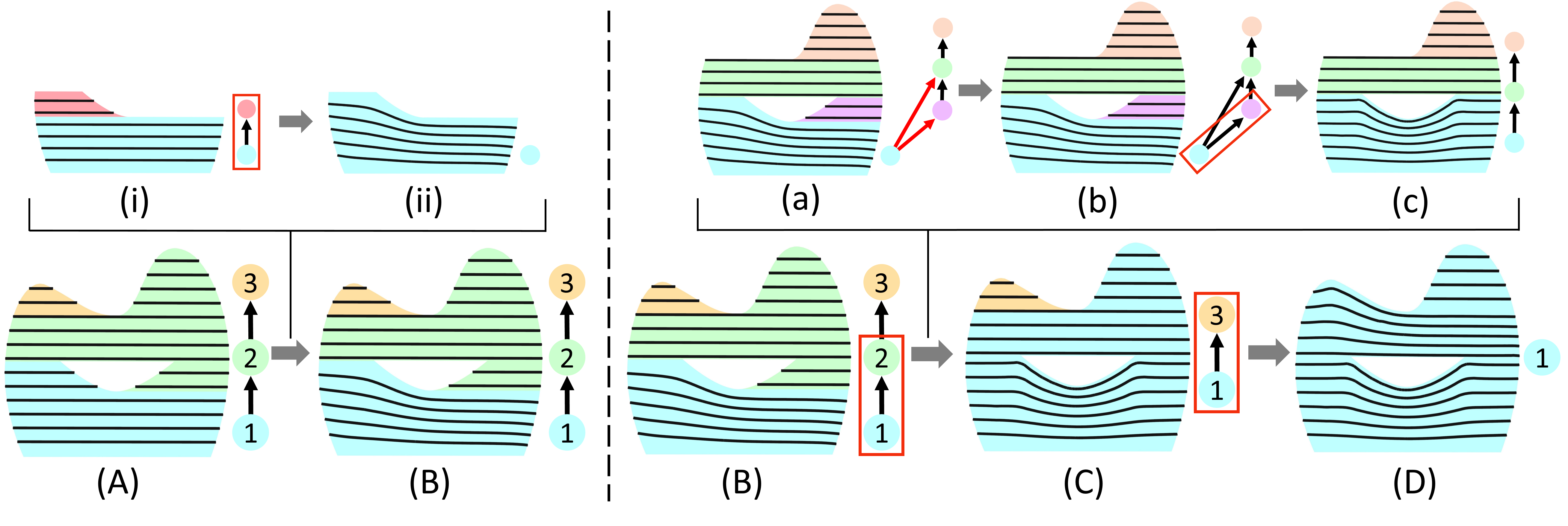
In our case, the directed edges of OPP graph indicate dependency relationships of OPPs. While merging a pair of nodes, one necessary criterion is to guarantee there are no multiple paths between the two nodes, since it will result in a deadlock of dependency after merging, shown in Figure 10(right). Another criterion is that the curving operation can be applied to the two OPPs (sub-OPP) nodes. The two merging processes are demonstrated in Figure 11(AB) and (BD). For each iteration of OPP Merging Process, we aim to merge two OPP nodes with the curving operation, which is taken as an inner loop of the OPP Merging Process (see ac in Figure 11).
Inner Loop of OPP Merging Process
As for the inner loop, a DAG can be formulated from the two candidate merging OPP nodes: 1) take their sequences of sub-OPPs where each sub-OPP is a node and maintain the dependency edges of these sub-OPPs; 2) add back the associated dependency edges between the two sequences from . While applying the pairwise merging strategy to the result DAG (Figure 11(ac)), we only select edges that benefit merging the two sequences to a single sequence. Specifically, we label the nodes that have edges across the two sub-OPP sequences (two red edges shown in (a)), then select edges over such labeled nodes. For each pair of nodes, call curving operation to merge the two nodes (subsection 3.3). The pseudo-code is presented in Appendix E.
![[Uncaptioned image]](https://cdn.awesomepapers.org/papers/340228cd-859d-44d6-82b2-7a5b7654e2be/differentCombination.png)
Optimality of Proposed Method
For different of input, the final number of nodes after merging may be different. We randomly select one with the least number of nodes since we only consider the OPP number criterion. Different and order of merging OPPs by curving may result in curved layers with different distributions, in other words, different sub-OPP of the final III-OPP, as shown in the inset. Similarly, since the order of selecting nodes in two levels is random, we cannot guarantee the global optimal solution. Figure 23 shows an example, and more details are discussed in Appendix D.
4.4. Layers Connection
With the bottom-up merging OPP process, we get an optimal OPP decomposition. This section works on path planning for each OPP by converting OPP slicing layers to continuous toolpath and generating transfer moves between OPPs. Note that we remove the most time-consuming smooth term of CurviSilcer while applying the curving operation during OPP merging (subsection 3.3). Here we add it back and rebuild the smoother curved layers of related OPPs for the toolpath planning. Then connect inter-layer to a single path for each OPP and determine the fabrication order of these OPP paths.
Inter-layer Connection Path
Since there are only in 2D models, they can be connected using Zig-zag pattern. For the two terminal points of a segment, if one is the entry point, the other will be the exit point. We select entry points for all , minimize the total length of the connection path between the entry and exit points of adjacent . Then we set a Euclidean distance threshold to determine whether two terminal points of two neighboring layers can be connected directly with a straight segment.
![[Uncaptioned image]](https://cdn.awesomepapers.org/papers/340228cd-859d-44d6-82b2-7a5b7654e2be/extraPath.png)
If the distance exceeds , an extra path is added. See the inset, call the current terminal point in the current layer , and the terminal point to be connected in the next layer . Print along the current printed layer with layer thickness from to the position closest to , and then print along straight line to (the orange path in the inset). The post path optimization in section 6 will improve the spatial distribution of the generated extra path.
OPPs Sequence
With the known dependency relationships of these OPP paths, we apply a method as subsection 4.2 to produce a feasible fabrication order. Then, we plan travel moves between OPP paths by withdrawing the nozzle to a safe distance above the printed objects to avoid possible collisions (see Figure 1). Finally, a G-code file is generated to transfer the toolpath to the printer.
5. Global Collision Considerations
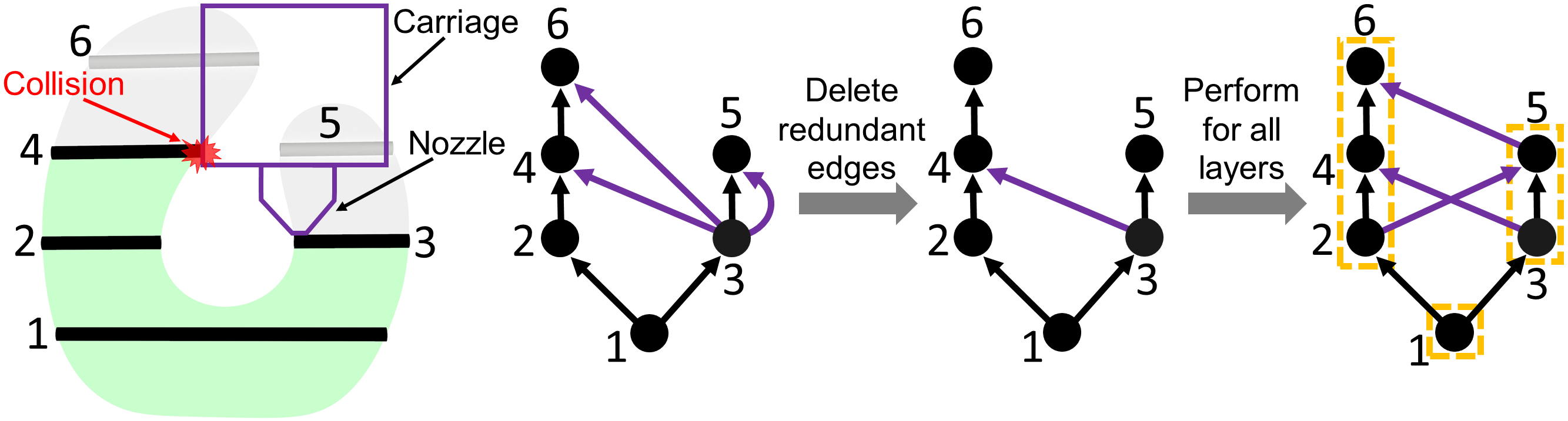
The algorithm of section 4 does not consider the global collision raised by the printed parts exceeding the nozzle length shown in Figure 12(a), which often occurs when printing a lower layer after the higher parts. To extend our method with this consideration, the key challenge is how to represent the global collision constraint in our proposed bottom-up OPP merging algorithm. We intend to formulate such constraints to a new type of directed edges of the OPP graph, named ”collision dependency edges.” Similar to the original directed edges, the new edges would represent printing dependencies. The difference is that the OPP nodes of the new edges cannot be merged through stacking operations. We would first clarify the generation of collision dependency edges and then introduce the algorithm’s modifications raised by the new edges.
(a) (b) (c) (d)
Generation of Collision Dependency Edges
To append the novel edges of , we apply the same method to model the printing nozzle in subsection 3.1. For each node pair of , add a collision dependency edge between them if a collision occurs while printing. As the layer ”3” and ”4” in Figure 12(a), the collision indicates that the layer ”4” must be printed after the layer ”3”. Note that we maintain as a Hasse diagram [Pemmaraju and Skiena, 2003], where redundant dependency edges do not exist. For example, if exist two edges: AB and BC, then AC is a redundant edge. The example in Figure 12(b) shows that three candidate collision dependency edges starting from the node ”3” has been compressed into one single edge (c).
Algorithm Modifications
1) For subsection 3.3, we need to add a requirement for applying curving operation, to guarantee no collision dependency between the top and bottom target flat areas of two OPPs. 2) For subsection 4.2, the method of path cover solution exploration remains the same as above. However, suppose a node of path cover solution space () includes sub-OPP nodes with ”collision dependency edges”, these sub-OPP nodes cannot be merged in . 3) For subsection 4.3, we observe that the number of OPP nodes (6 nodes) in becomes much more than that without including collision dependency edges (3 nodes indicated with orange boxes), as shown in Figure 12(d). To solve the efficiency problem raised by the increasing of OPP nodes, especially for the OPP merging procedure with curved layers, we add an external step before the Initial Merging Process. That is to apply the stacking operation for sub-OPPs of each OPP node according to the which is generated without considering the global collisions.
6. Extension to 3D
Extending our algorithm from 2D to 3D does not require extra effort for most steps, except to deal with contour in the construction step and extend the toolpath generation step for the 3D case. In this section, we describe the extension of these steps in detail.
Initial OPP Graph
For 3D cases with contours, we first build a with the method of subsection 4.2. If an OPP node of has both segments and contours, divide it into pure segment nodes and pure contour nodes. Such classification is conducive to the next step of merging via curving, which only allows the input of two OPPs composed of segments, or one OPP composed entirely of segments, and the other entirely of contours.
Contour Spiralization
To spiralize contours (,…), we need first to determine one connecting point for each contour. As subsection 4.4, we aim to minimize the total distance between connecting points of adjacent contours. We design a dynamic programming algorithm to choose appropriate connecting points for each contour. We discretize each contour with sampling points, where is a sampling point in . Denote as the minimum sum of length between neighboring contours ,… when choosing as connecting point. The transition equation is as below.
Then, we connect these contours by spiral path, shown in Figure 13. For each two adjacent contours, interpolate all sampling points starting from the connecting points:
where is a sampling point of the below contour (if , is connecting point of current contour), is the nearest point to of the above contour, is total length of the below contour, is the geodesic distance that moves from the connecting point along the below contour, is the interpolation point. Note that the top contour as a boundary will not be spiralized.
Filling the Low-Slope Area
While slicing, inadequate layers over low-slope regions inevitably result in under-fills, as shown in Figure 14(left). Such under-fills of small areas can be removed by a post path optimization process (see Figure 15 left bottom). For large under-fill areas, we propose to fill them with connected Fermat spirals [Zhao et al., 2016]. In our implementation, we set a threshold of to detect the Fermat spiral region. We traverse each pair of the adjacent contours, generate the matching edges between the sampling points of two contours by minimal Euclidean distance, and measure the angle of these matching edges from the horizontal plane. If all angles of these matching edges are smaller than the threshold, add the surface patch between the two contours to the Fermat spiral region. Figure 14(right) shows the filling path over the original 3D surface.
Toolpath Optimization
Since we generate toolpath for each OPP separately, the adjacent paths may be too close or too far from each other (left center of Figure 15(left)). Some inter-layer connection paths (subsection 4.4) and the filling paths of low slope areas (left bottom of Figure 15(left)) may be not uniformly distributed (left top of Figure 15(left)). To eliminate these problems, we use a similar method as [Zhao et al., 2018] to optimize the final toolpath, in which they iteratively evolve a single toolpath considering the spacing and smoothing constraints. Different from the original method, our input is not a single path but multiple continuous paths. Figure 15 shows a result before and after optimization.
7. Results and Discussions
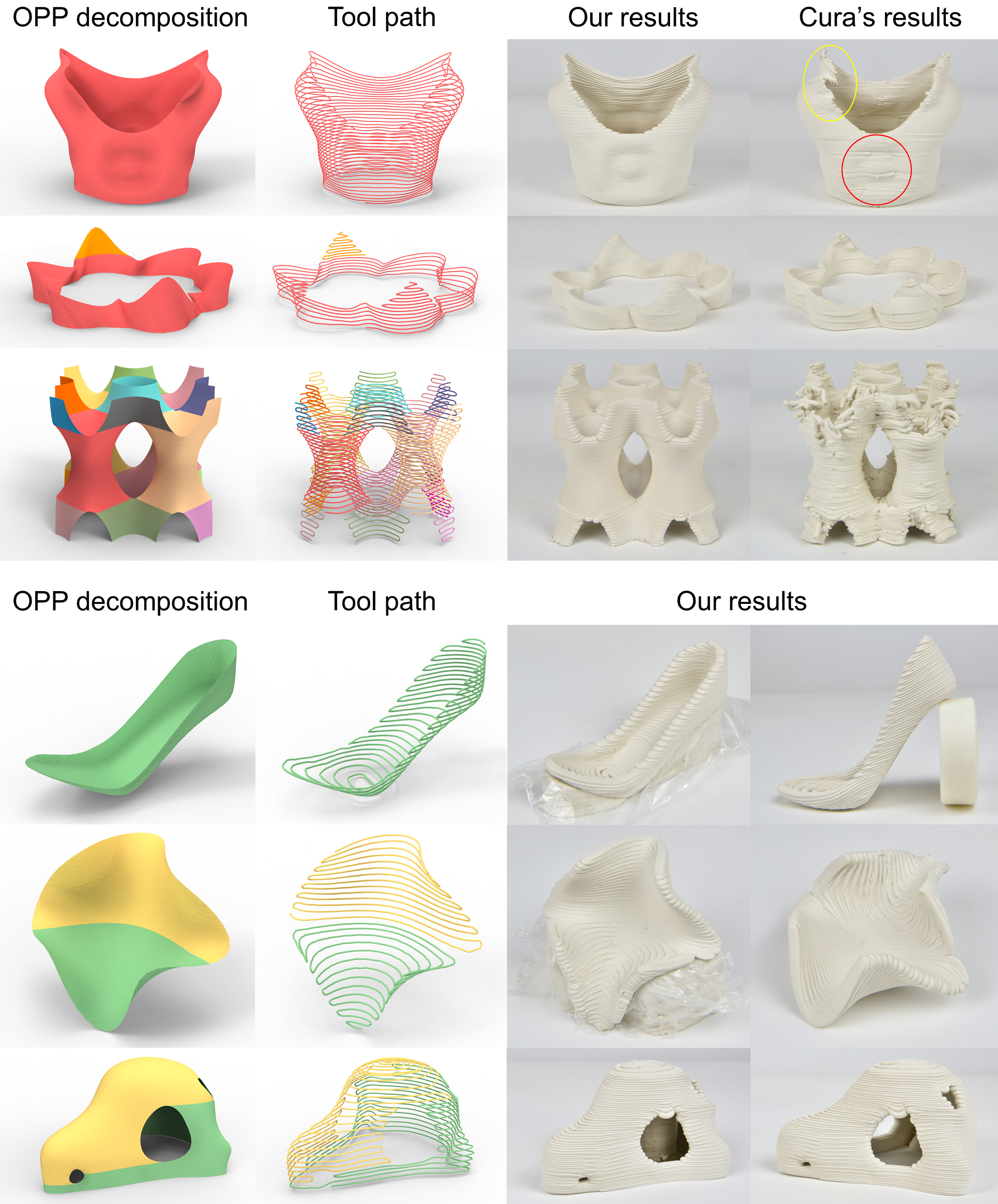
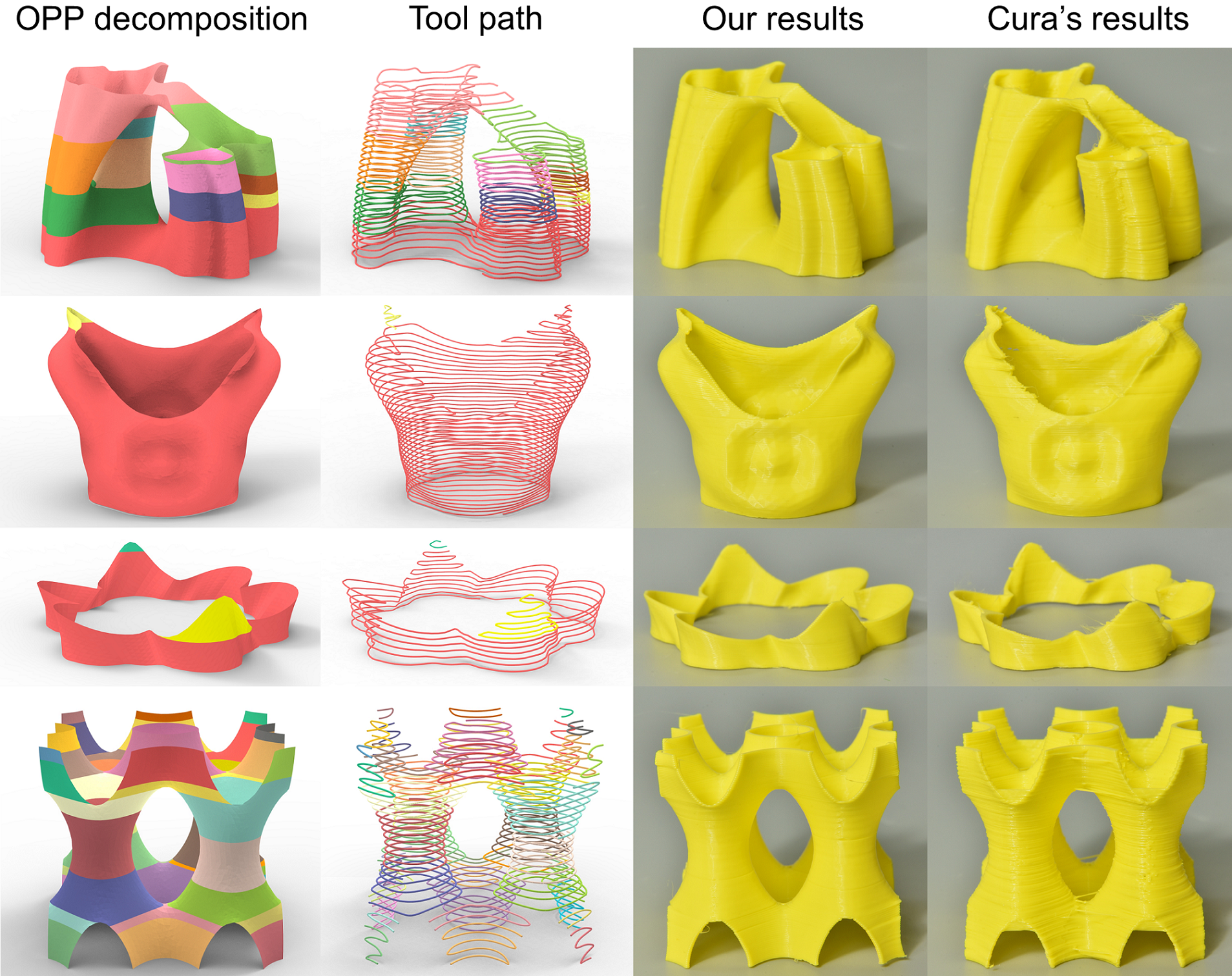
This section shows OPP decomposition results on surface models with varying geometric complexity, printed results, and comparisons with the Ultimaker Cura 4.9.1 software. We evaluate our ACAP algorithm on DIW-based ceramic printing and FDM platforms, with clay and thermoplastics as the material, respectively.
7.1. Implementation and Parameters
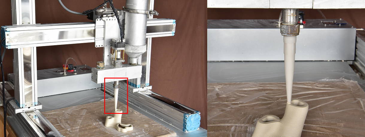
Our algorithm is implemented with C++, running on a PC with an Intel Core i7-9700 CPU @ 3.0GHz and 32GB memory. For the printing experiments, we use a 3-axis DIW ceramic printer Eazao Mega 5 with 470×370×390 printing volume (Figure 16) and an FDM printer Hori Z560 with 360×350×500 printing volume. Note that the parameters below in the brackets refer to the FDM. For the ceramic printing (FDM) printer, we use a 90 (8) long nozzle with the nozzle diameter of 5.2 (1.0) (Figure 16 shows the ceramic printer’s nozzle), nozzle movement speed as 25.0 (25.0). The printing path width is set to 6 (1.5). In subsection 3.1, we take the average of the layer thickness range, i.e., 1.5 (0.35) for calculating slope angle constraint, which is 30∘ (35∘) according to the formulation. We set the flat layer thickness to 1.0 (0.2) for slicing, producing the best surface quality in our experiments, and also use it as the slicing layer thickness to slice models and generate . The distance threshold is 5 (2) in connecting layers (subsection 4.4).
7.2. Fabrication Results
| Model | H | #OF | #OO | #OC | |||
|---|---|---|---|---|---|---|---|
![[Uncaptioned image]](https://cdn.awesomepapers.org/papers/340228cd-859d-44d6-82b2-7a5b7654e2be/juliaVaseIco.png) Julia vase
Julia vase
|
81 | 8 | 4 | 832 | 17.7 | 34.3 | 48% |
![[Uncaptioned image]](https://cdn.awesomepapers.org/papers/340228cd-859d-44d6-82b2-7a5b7654e2be/grailIco.png) Grail
Grail
|
120 | 2 | 1 | 1541 | 20.1 | 26.7 | 25% |
![[Uncaptioned image]](https://cdn.awesomepapers.org/papers/340228cd-859d-44d6-82b2-7a5b7654e2be/crownIco.png) Crown
Crown
|
38 | 6 | 2 | 116 | 8.3 | 12.5 | 34% |
![[Uncaptioned image]](https://cdn.awesomepapers.org/papers/340228cd-859d-44d6-82b2-7a5b7654e2be/tpmsIco.png) TPMS
TPMS
|
95 | 18 | 18 | 3332 | 37.3 | 58.5 | 36% |
![[Uncaptioned image]](https://cdn.awesomepapers.org/papers/340228cd-859d-44d6-82b2-7a5b7654e2be/shoeIco.png) Shoe
Shoe
|
52 | 2 | 1 | N/A | 20.7 | N/A | N/A |
![[Uncaptioned image]](https://cdn.awesomepapers.org/papers/340228cd-859d-44d6-82b2-7a5b7654e2be/oceanIco.png) Ocean
Ocean
|
79 | 4 | 2 | N/A | 59.5 | N/A | N/A |
![[Uncaptioned image]](https://cdn.awesomepapers.org/papers/340228cd-859d-44d6-82b2-7a5b7654e2be/caraIco.png) Mask
Mask
|
54 | 6 | 2 | N/A | 8.6 | N/A | N/A |
![[Uncaptioned image]](https://cdn.awesomepapers.org/papers/340228cd-859d-44d6-82b2-7a5b7654e2be/juliaVaseIco2.png) Julia vase
Julia vase
|
41 | 15 | 11 | 741 | 19.8 | 35.0 | 43% |
![[Uncaptioned image]](https://cdn.awesomepapers.org/papers/340228cd-859d-44d6-82b2-7a5b7654e2be/grailIco2.png) Grail
Grail
|
60 | 3 | 2 | 1487 | 24.0 | 31.4 | 24% |
![[Uncaptioned image]](https://cdn.awesomepapers.org/papers/340228cd-859d-44d6-82b2-7a5b7654e2be/crownIco2.png) Crown
Crown
|
19 | 7 | 3 | 311 | 8.8 | 12.7 | 31% |
![[Uncaptioned image]](https://cdn.awesomepapers.org/papers/340228cd-859d-44d6-82b2-7a5b7654e2be/tpmsIco2.png) TPMS
TPMS
|
48 | 44 | 44 | 2971 | 34.5 | 51.4 | 33% |
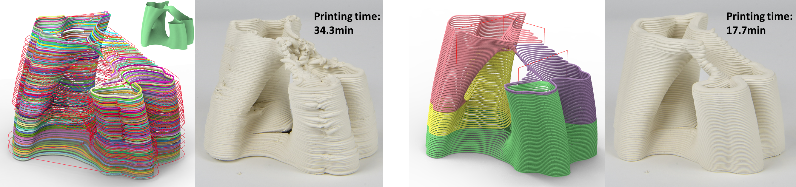
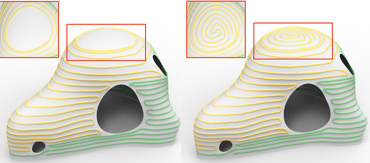
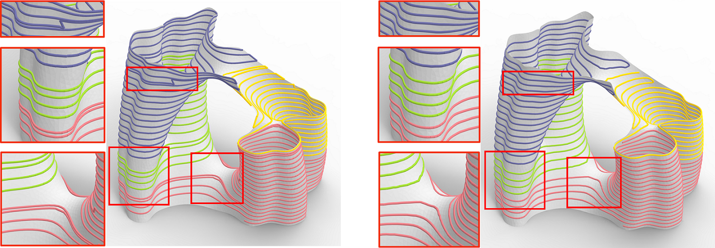
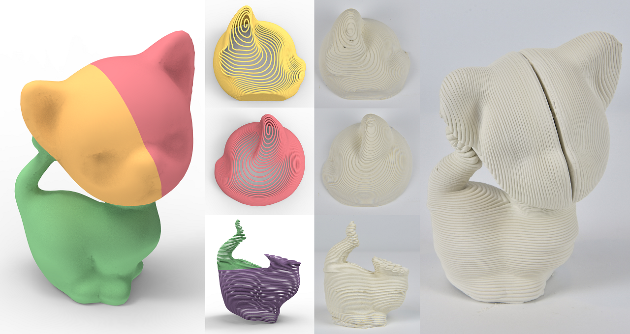
Figure 1, Figure 17 and Figure 18 show results of two different printing processes (ceramic printing and FDM), including OPP decomposition, printing path, and printed models (using our method and Cura, respectively). Refer to Table 1 for the statistics, where we list each model’s height, the number of OPPs produced by our algorithm, and the printing time raised by our method and Cura software. Specifically, the table includes the number of OPPs after merging through flat layers (#OF), and the number of OPPs after merging through curved layers (#OO), to illustrate the effectiveness of stacking and curving operations. Note that we scale models to half size in FDM experiments for time saving. Since the nozzle used for FDM printing is much shorter than for ceramic printing, our method partitions more OPPs to avoid the global collisions.
Compare with Cura
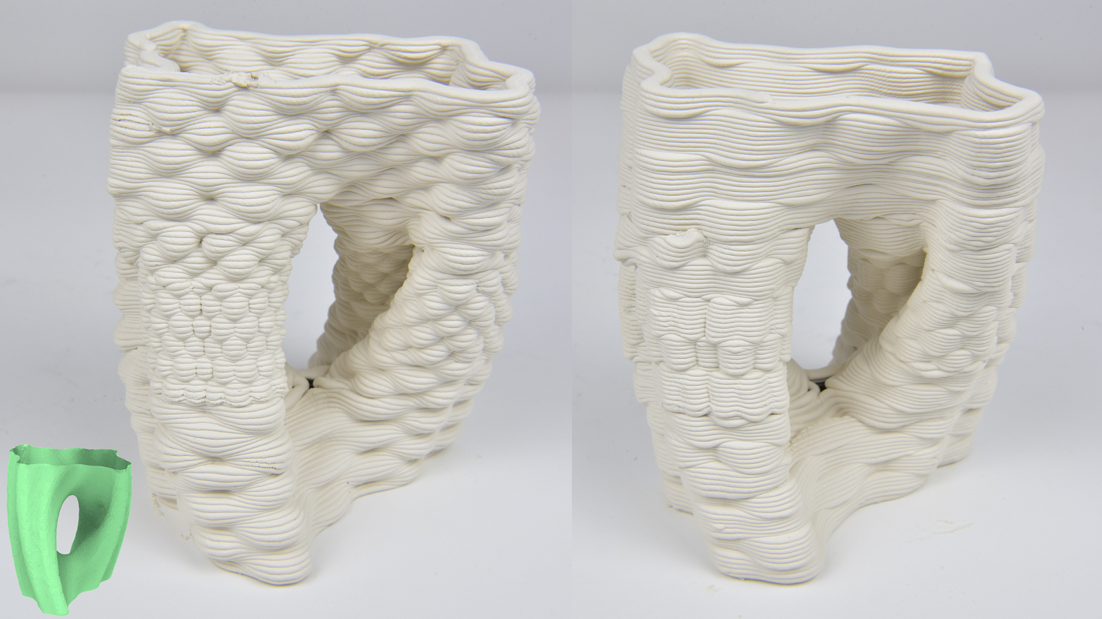
The top three models in Figure 17 and the four models in Figure 18 are all self-supporting. In the setting of Cura, we choose the Surface Mode, enable Spiralize Outer Contour and Retraction, and use the same nozzle movement speed as our method. It shows that our method outperforms Cura for shell models containing multiple contours or segments in both surface quality (fewer artifacts and slighter deformation) and fabrication efficiency (save 24%48% of printing time). For example, as the Grail model printed with Cura (ceramic printing), a large number of transfer moves (1541) induce deformation (see the red circle in Figure 17). Such transfer moves would increase the forces on the printed part and may cause the collapse (see the yellow circle). In contrast, the ACAP toolpath for this model only has one transfer move in FDM, and even no transfer move in ceramic printing, and thus strengthens the model during fabrication and avoids these problems. Generally, our algorithm improves the printing efficiency more significantly for the models with multiple branches like the Julia vase or TPMS model. Moreover, we can see the benefit of curved layers, which reduces the number of OPPs by around 50%, and improves the staircase defect (see the upper part of the Crown model). The TPMS model has no curved layer, as the slope angle constraint restricts it.
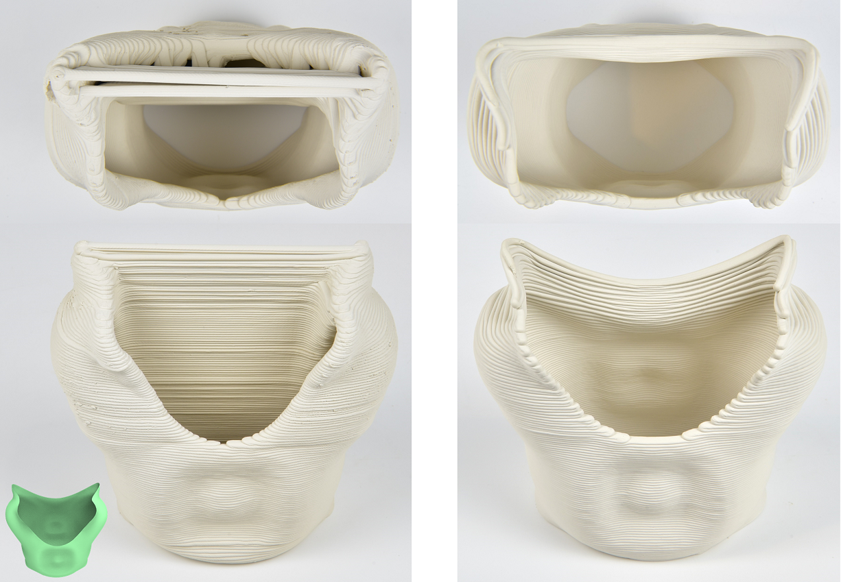
For the models that require support structures, we pre-build the support structures and place them before printing the models. See the last three models in Figure 17. To make support structure easy to remove, we add a membrane on the surface of their contact before printing the model.
Discussions on the printing quality
Generally, the quality of ceramic printing is more sensitive to toolpath continuity for surface models than FDM printing. Therefore, the clay results from the ACAP algorithm show significant superiority in the model quality over those from Cura. However, we can still observe some visible artifacts in the clay printouts, like over-extrusion at the zig-zag turning areas, seams at the junction of OPPs, and sagging at the concavity corner. The primary reason is that the DIW-based ceramic printing technique with clay is less mature than FDM with thermoplastics. The extrusion amount can hardly be precisely controlled due to material inertia. Moreover, there are many uncertainties during the fabrication process, such as material humidity, air pressure, and other coupled hardware and material problems.
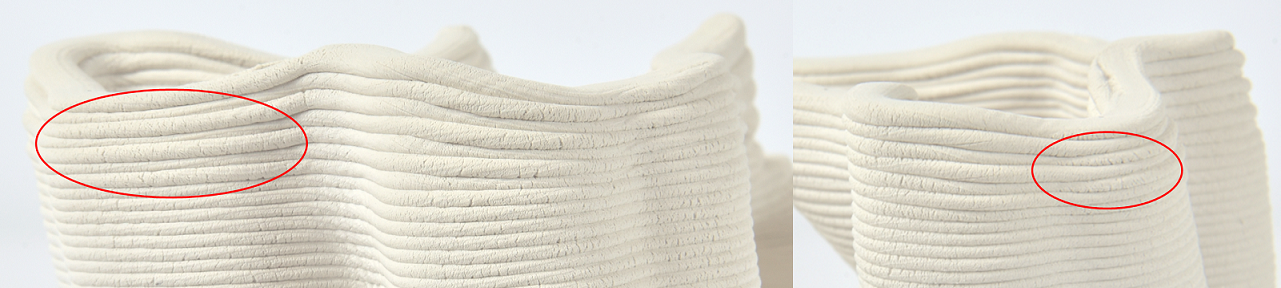
We also remark a defect in curved layers. See Figure 19; we observe that the layer thickness is non-uniform in the outer boundary, appearing like the stair-case defect. The reason is that curved slicing layers are applied with adaptive layer thickness, and the material deforms in different behaviors when extruded in downhill or uphill directions. Such artifact might be improved via fine-tuning the material flow or the nozzle height, while highly demanding on three issues: stable properties of the clay material, accurate simulation of clay deformation, and precise control of the extrusion rate for clay in the printing platform.
7.3. Algorithm Performance
| Section 4.1 | Section 4.2 | Section 4.3 | 4.4 | 5 | All | ||||||||
|---|---|---|---|---|---|---|---|---|---|---|---|---|---|
| Model | #DN | #DE | #IN | #IE | #BS | #SO | #CU | ||||||
|
|
81 | 209 | 17 | 19 | 8 | 128 | 768 | 315 | 246 | 326 | 887 | ||
|
|
120 | 146 | 4 | 3 | 2 | 2 | 4 | 3 | 497 | 438 | 938 | ||
|
|
38 | 91 | 9 | 8 | 6 | 16 | 96 | 39 | 313 | 144 | 496 | ||
|
|
95 | 598 | 38 | 48 | 18 | 3 | 96 | 0 | 3 | 1 | 455 | 462 | |
|
|
52 | 64 | 3 | 2 | 2 | 2 | 2 | 2 | 84 | 53 | 139 | ||
|
|
79 | 97 | 7 | 9 | 4 | 2 | 8 | 7 | 419 | 94 | 520 | ||
|
|
57 | 122 | 12 | 15 | 6 | 121 | 741 | 274 | 290 | 242 | 806 | ||
|
|
205 | 1254 | 443 | 1182 | 15 | 3 | 48 | 288 | 127 | 274 | 495 | 899 | |
|
|
300 | 415 | 107 | 157 | 3 | 2 | 2 | 1 | 440 | 524 | 965 | ||
|
|
190 | 1043 | 384 | 971 | 7 | 28 | 196 | 131 | 298 | 257 | 686 | ||
|
|
240 | 3836 | 905 | 3295 | 44 | 37 | 1 | 0 | 1 | 573 | 612 | ||
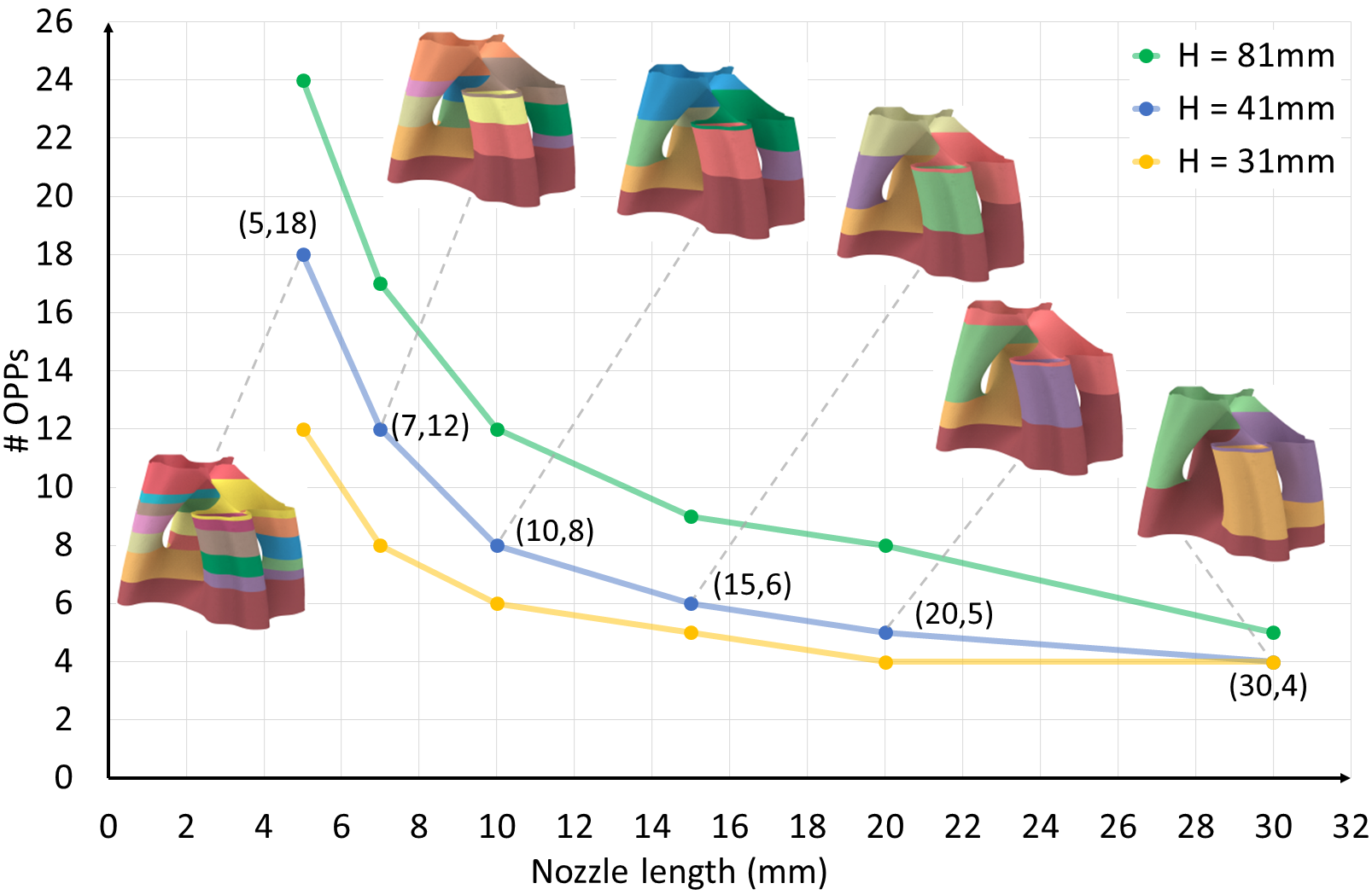
Effect of nozzle length
The nozzle size, especially the nozzle length, also affects the number of OPPs, as the shorter nozzle indicates more possibilities for the collision between the model and the printing platform. See Figure 20, we test the nozzle length from 5mm to 30mm on the Julia vase model in three different sizes.
Running time
Table 2 shows the running time statistics with the number of nodes and edges of the OPP graph during each step of our ACAP algorithm. For most of the input models, our algorithm is extremely efficient in the generation of , and , since our algorithm does not involve any geometric computation in this phase, but only some graph operations. The only exception is the TPMS model (FDM), whose time of building is much longer than that of other models, since it owns a large number of nodes and edges in (905 and 3295) with more iterations of beam search (44). The running time of OPP merging through curved layers varies mainly according to the number of (#SO) and calls to CurviSlicer (#CU), where CurviSlicer is the bottleneck to speed up this step. Similarly, the time of layers connection () is also time-consuming, which would apply CurviSlicer with the smooth term for each decomposed OPP patch. Besides, the toolpath optimization also takes a long time, worth improving.
8. Conclusion, Limitation, and Future work
In extrusion-based 3D printing, path continuity significantly impacts the surface quality and printing time, especially for shell models. We put forward the original concept of OPP to quantify path continuity and propose a method to decompose the given shell model into as few OPPs as possible, considering manufacturing constraints on a standard three-axis printer platform. We demonstrated our methods on various models, and the results are superior to existing methods in surface finish and printing time.
Limitations and Future work
Regarding the toolpath, improvement space still exists. The inter-layer connecting path might be outside the model by a distance , and such an artifact cannot be guaranteed to be avoided through the post global toolpath optimization. The constant path width maintains the uniform horizontal wall thickness of the shell model; however, the shell thickness in the direction normal to the surface varies, which is an unintended consequence.
Our framework only allows for geometry to be printed which is surface model. Extending the OPP criterion and the ACAP algorithm to general solid models could be valuable continuous work. The key issue is how to adapt the OPP criterion to different interior structures or infilling patterns. Moreover, to fully explore the applications of surface models, applying the shell reinforcement techniques like adding ribs [Gil-Ureta et al., 2020] or modulating the thickness [Xing et al., 2021] is also an exciting direction. In such a way, the contour of the surface models is of varying thickness. The ACAP algorithm should be adapted to combine both thin regions of +/- the nozzle size and wider ranges of multiple nozzle sizes.
The support structure constraint limits the feasible surface shapes for fabrication, i.e., the model is either self-supporting or with the support structures located on the ground. Thus, for models with no orientation satisfying the support structure constraint, we decompose the model manually and assemble them afterwards, as shown in Figure 21. We remark that different degrees of shrinkage of material may leave noticeable seam lines between parts after solidifying of materiel. In future work, we would like to study the generalization of more complex surface models by considering more decoupling strategies between the support and intact structures, and also the scheduling strategies for printing the support structures in-situ with the intact model. An automated pre-decomposition that balances the number of decomposed patches and path continuity is also a natural objective.
Since our method generates the toolpath and related G-code files, it would be natural to cooperate with the research works that fine-tune the printing parameters like the extruder height and extrusion amount [Takahashi and Miyashita, 2017], or positions in a local range [Yan et al., 2021], to achieve various delicate geometric features without violating the toolpath continuity. Referring to Figure 22, each OPP can be treated as an independent unit to embed different textures on the fly.
Finally, another problem worth exploring is extending the algorithm to multi-axis printing setups. Accordingly, the slope angle constraint can be ignored, the support structures are of fewer restrictions, and the toolpath has more freedom. We believe the research direction owns great potential.
References
- [1]
- Allen and Trask [2015] Robert J.A. Allen and Richard S. Trask. 2015. An experimental demonstration of effective Curved Layer Fused Filament Fabrication utilising a parallel deposition robot. Additive Manufacturing 8 (oct 2015), 78–87. https://doi.org/10.1016/j.addma.2015.09.001
- Anton et al. [2019] Ana Anton, Angela Yoo, Patrick Bedarf, Lex Reiter, Timothy Wangler, and Benjamin Dillenburger. 2019. Vertical Modulations. Computational design for concrete 3D printed columns. In ACADIA 19: Ubiquity and Autonomy. Proceedings of the 39th Annual Conference of the Association for Computer Aided Design in Architecture, Kory Bieg, Danelle Briscoe, and Clay Odom (Eds.). Association for Computer Aided Design in Architecture (ACADIA), s.l., 596 – 605.
- Bhatt et al. [2020] Prahar M. Bhatt, Rishi K. Malhan, Pradeep Rajendran, and Satyandra K. Gupta. 2020. Building free-form thin shell parts using supportless extrusion-based additive manufacturing. Additive Manufacturing 32 (mar 2020), 101003. https://doi.org/10.1016/j.addma.2019.101003
- Bhooshan et al. [2020] Shajay Bhooshan, Tom Van Mele, and Philippe Block. 2020. Morph & Slerp: Shape description for 3D printing of concrete. Symposium on Computational Fabrication (nov 2020). https://doi.org/10.1145/3424630.3425413
- B.Huang and S.Singamneni [2012] B.Huang and S.Singamneni. 2012. Alternate slicing and deposition strategies for fused deposition modelling of light curved parts. Journal of achievements in materials and manufacturing engineering 55 (2012), 511–517.
- Burger et al. [2020] Joris Burger, Ena Lloret-Fritschi, Fabio Scotto, Thibault Demoulin, Lukas Gebhard, Jaime Mata-Falcón, Fabio Gramazio, Matthias Kohler, and Robert J. Flatt. 2020. Eggshell: Ultra-Thin Three-Dimensional Printed Formwork for Concrete Structures. 3D Printing and Additive Manufacturing 7, 2 (apr 2020), 48–59. https://doi.org/10.1089/3dp.2019.0197
- Chakraborty et al. [2008] Debapriya Chakraborty, B. Aneesh Reddy, and A. Roy Choudhury. 2008. Extruder path generation for Curved Layer Fused Deposition Modeling. Computer-Aided Design 40, 1 (feb 2008), 235–243. https://doi.org/10.1016/j.cad.2007.10.014
- Chan et al. [2020] Shareen S.L. Chan, Ryan M. Pennings, Lewis Edwards, and George V. Franks. 2020. 3D printing of clay for decorative architectural applications: Effect of solids volume fraction on rheology and printability. Additive Manufacturing 35 (oct 2020). https://doi.org/10.1016/j.addma.2020.101335
- Chen et al. [2019a] Lufeng Chen, Man-Fai Chung, Yaobin Tian, Ajay Joneja, and Kai Tang. 2019a. Variable-depth curved layer fused deposition modeling of thin-shells. Robotics and Computer-Integrated Manufacturing 57 (jun 2019), 422–434. https://doi.org/10.1016/j.rcim.2018.12.016
- Chen et al. [2019b] Zhangwei Chen, Ziyong Li, Junjie Li, Chengbo Liu, Changshi Lao, Yuelong Fu, Changyong Liu, Yang Li, Pei Wang, and Yi He. 2019b. 3D printing of ceramics: A review. Journal of the European Ceramic Society 39, 4 (apr 2019), 661–687. https://doi.org/10.1016/j.jeurceramsoc.2018.11.013
- Dai et al. [2018] Chengkai Dai, Charlie C. L. Wang, Chenming Wu, Sylvain Lefebvre, Guoxin Fang, and Yong-Jin Liu. 2018. Support-free volume printing by multi-axis motion. ACM Transactions on Graphics 37, 4 (aug 2018), 1–14. https://doi.org/10.1145/3197517.3201342
- Etienne et al. [2019] Jimmy Etienne, Nicolas Ray, Daniele Panozzo, Samuel Hornus, Charlie C. L. Wang, Jonàs Martínez, Sara McMains, Marc Alexa, Brian Wyvill, and Sylvain Lefebvre. 2019. CurviSlicer: Slightly curved slicing for 3-axis printers. ACM Transactions on Graphics 38, 4 (jul 2019), 1–11. https://doi.org/10.1145/3306346.3323022
- Ezair et al. [2018] Ben Ezair, Saul Fuhrmann, and Gershon Elber. 2018. Volumetric covering print-paths for additive manufacturing of 3D models. Computer-Aided Design 100 (jul 2018), 1–13. https://doi.org/10.1016/j.cad.2018.02.006
- Fang et al. [2020] Guoxin Fang, Tianyu Zhang, Sikai Zhong, Xiangjia Chen, Zichun Zhong, and Charlie C. L. Wang. 2020. Reinforced FDM: multi-axis filament alignment with controlled anisotropic strength. ACM Transactions on Graphics 39, 6 (nov 2020), 1–15. https://doi.org/10.1145/3414685.3417834
- Gil-Ureta et al. [2020] Francisca Gil-Ureta, Nico Pietroni, and Denis Zorin. 2020. Reinforcement of General Shell Structures. ACM Transactions on Graphics 39, 5 (sep 2020), 1–19. https://doi.org/10.1145/3375677
- Hergel et al. [2019] Jean Hergel, Kevin Hinz, Sylvain Lefebvre, and Bernhard Thomaszewski. 2019. Extrusion-based ceramics printing with strictly-continuous deposition. ACM Transactions on Graphics 38, 6 (nov 2019), 1–11. https://doi.org/10.1145/3355089.3356509
- Herholz et al. [2015] Philipp Herholz, Wojciech Matusik, and Marc Alexa. 2015. Approximating free-form geometry with height fields for manufacturing. Computer Graphics Forum 34, 2 (2015), 293–251. https://doi.org/10.1111/cgf.12556
- Hildebrand et al. [2013] Kristian Hildebrand, Bernd Bickel, and Marc Alexa. 2013. Orthogonal slicing for additive manufacturing. Computers & Graphics 37, 6 (2013), 669–675. https://doi.org/10.1016/j.cag.2013.05.011
- Hornus et al. [2020] Samuel Hornus, Tim Kuipers, Olivier Devillers, Monique Teillaud, Jonàs Martínez, Marc Glisse, Sylvain Lazard, and Sylvain Lefebvre. 2020. Variable-width contouring for additive manufacturing. ACM Transactions on Graphics 39, 4 (jul 2020). https://doi.org/10.1145/3386569.3392448
- Hu et al. [2014] Ruizhen Hu, Honghua Li, Hao Zhang, and Daniel Cohen-Or. 2014. Approximate Pyramidal Shape Decomposition Ruizhen. ACM Transactions on Graphics 33, 213 (nov 2014), 1–12. https://doi.org/10.1145/2661229.2661244
- Kubo and Kasugai [1991] Mikio Kubo and Hiroshi Kasugai. 1991. The precedence constrained traveling salesman problem. Journal of the Operations Research Society of Japan 34, 2 (1991), 152–172. https://doi.org/10.15807/jorsj.34.152
- Kuipers et al. [2020] Tim Kuipers, Eugeni L. Doubrovski, Jun Wu, and Charlie C.L. Wang. 2020. A Framework for Adaptive Width Control of Dense Contour-Parallel Toolpaths in Fused Deposition Modeling. Computer-Aided Design 128 (nov 2020), 102907. https://doi.org/10.1016/j.cad.2020.102907
- Lensgraf and Mettu [2016] Samuel Lensgraf and Ramgopal R. Mettu. 2016. Beyond layers: A 3D-aware toolpath algorithm for fused filament fabrication. In 2016 IEEE International Conference on Robotics and Automation (ICRA). IEEE. https://doi.org/10.1109/icra.2016.7487546
- Lensgraf and Mettu [2017] Samuel Lensgraf and Ramgopal R. Mettu. 2017. An improved toolpath generation algorithm for fused filament fabrication. In 2017 IEEE International Conference on Robotics and Automation (ICRA). IEEE. https://doi.org/10.1109/icra.2017.7989141
- Lensgraf and Mettu [2018] Samuel Lensgraf and Ramgopal R. Mettu. 2018. Incorporating Kinematic Properties into Fused Deposition Toolpath Optimization. In 2018 IEEE/RSJ International Conference on Intelligent Robots and Systems (IROS). IEEE. https://doi.org/10.1109/iros.2018.8594398
- Li et al. [2021] Yamin Li, Kai Tang, Dong He, and Xiangyu Wang. 2021. Multi-Axis Support-Free Printing of Freeform Parts with Lattice Infill Structures. Computer-Aided Design 133 (apr 2021), 102986. https://doi.org/10.1016/j.cad.2020.102986
- Llewellyn-Jones et al. [2016] Thomas Llewellyn-Jones, Robert Allen, and Richard Trask. 2016. Curved Layer Fused Filament Fabrication Using Automated Toolpath Generation. 3D Printing and Additive Manufacturing 3, 4 (dec 2016), 236–243. https://doi.org/10.1089/3dp.2016.0033
- Luo et al. [2012] Linjie Luo, Ilya Baran, Szymon Rusinkiewicz, and Wojciech Matusik. 2012. Chopper: Partitioning Models into 3D-Printable Parts. ACM Transactions on Graphics 31, 129 (nov 2012), 1–9. https://doi.org/10.1145/2366145.2366148
- Mahdavi-Amiri et al. [2020] Ali Mahdavi-Amiri, Fenggen Yu, Haisen Zhao, Adriana Schulz, and Hao Zhang. 2020. VDAC: volume decompose-and-carve for subtractive manufacturing. ACM Transactions on Graphics (TOG) 39, 6 (2020), 1–15.
- Mitropoulou et al. [2020] Ioanna Mitropoulou, Mathias Bernhard, and Benjamin Dillenburger. 2020. Print Paths Key-framing. In Symposium on Computational Fabrication. ACM. https://doi.org/10.1145/3424630.3425408
- Muntoni et al. [2018] Alessandro Muntoni, Marco Livesu, Riccardo Scateni, Alla Sheffer, and Daniele Panozzo. 2018. Axis-Aligned Height-Field Block Decomposition of 3D Shapes. ACM Transactions on Graphics 37, 5 (nov 2018), 1–15. https://doi.org/10.1145/3204458
- Ordoñez et al. [2019] Edisson Ordoñez, Jhon M. Gallego, and Henry A. Colorado. 2019. 3D printing via the direct ink writing technique of ceramic pastes from typical formulations used in traditional ceramics industry. Applied Clay Science 182 (dec 2019). https://doi.org/10.1016/j.clay.2019.105285
- Pemmaraju and Skiena [2003] Sriram Pemmaraju and Steven Skiena. 2003. Computational Discrete Mathematics: Combinatorics and Graph Theory with Mathematica. Cambridge University Press. https://doi.org/10.1017/CBO9781139164849
- Peng et al. [2018] Erwin Peng, Danwei Zhang, and Jun Ding. 2018. Ceramic Robocasting: Recent Achievements, Potential, and Future Developments. ADVANCED MATERIALS (oct 2018). https://doi.org/10.1002/adma.201802404
- Revelo and Colorado [2018] Carlos F. Revelo and Henry A. Colorado. 2018. 3D printing of kaolinite clay ceramics using the Direct Ink Writing (DIW) technique. Ceramics International 44 (apr 2018), 5673–5682. https://doi.org/10.1016/j.ceramint.2017.12.219
- Takahashi and Miyashita [2017] Haruki Takahashi and Homei Miyashita. 2017. Expressive Fused Deposition Modeling by Controlling Extruder Height and Extrusion Amount. In Proceedings of the 2017 CHI Conference on Human Factors in Computing Systems. ACM. https://doi.org/10.1145/3025453.3025933
- Toussaint [1985] Godfried T Toussaint. 1985. Movable separability of sets. Machine Intelligence and Pattern Recognition 2 (1985), 335–375.
- Ultimaker [2021] Ultimaker. 2021. Ultimaker Cura 4.9.1. (2021). https://ultimaker.com/software/ultimaker-cura
- Vanek et al. [2014] J. Vanek, J. A. Garcia Galicia, B. Benes, R. Mech, N. Carr, O.Stava, and G.S. Miller. 2014. PackMerger: A 3D Print Volume Optimizer. Computer Graphics Forum 33, 6 (sep 2014), 322–332. https://doi.org/10.1111/cgf.12353
- Wei et al. [2018] Xiangzhi Wei, Siqi Qiu, Lin Zhu, Ruiliang Feng, Yaobin Tian, Juntong Xi, and Youyi Zheng. 2018. Toward Support-Free 3D Printing: A Skeletal Approach for Partitioning Models. IEEE TRANSACTIONS ON VISUALIZATION AND COMPUTER GRAPHICS 24, 10 (oct 2018), 2799–2812. https://doi.org/10.1109/TVCG.2017.2767047
- Wu et al. [2017] Chenming Wu, Chengkai Dai, Guoxin Fang, Yong-Jin Liu, and Charlie C.L. Wang. 2017. RoboFDM: A robotic system for support-free fabrication using FDM. In 2017 IEEE International Conference on Robotics and Automation (ICRA). IEEE. https://doi.org/10.1109/icra.2017.7989140
- Wu et al. [2020] Chenming Wu, Chengkai Dai, Guoxin Fang, Yong-Jin Liu, and Charlie C. L. Wang. 2020. General Support-Effective Decomposition for Multi-Directional 3-D Printing. IEEE Transactions on Automation Science and Engineering 17, 2 (apr 2020), 599–610. https://doi.org/10.1109/tase.2019.2938219
- Xia et al. [2020] Lingwei Xia, Sen Lin, and Guowei Ma. 2020. Stress-based tool-path planning methodology for fused filament fabrication. Additive Manufacturing 32 (mar 2020), 101020. https://doi.org/10.1016/j.addma.2019.101020
- Xing et al. [2021] Yu Xing, Yu Zhou, XinYan, Haisen Zhao, Wenqiang Liu, Jingbo Jiang, and Lin Lu. 2021. Shell thickening for extrusion-based ceramics printing. Computers & Graphics 97 (jun 2021), 160–169. https://doi.org/10.1016/j.cag.2021.04.031
- Xu et al. [2019] Ke Xu, Yingguang Li, Lufeng Chen, and Kai Tang. 2019. Curved layer based process planning for multi-axis volume printing of freeform parts. Computer-Aided Design 114 (sep 2019), 51–63. https://doi.org/10.1016/j.cad.2019.05.007
- Yan et al. [2021] Xin Yan, Lin Lu, Andrei Sharf, Xing Yu, and Yulu Sun. 2021. Man-made by Computer: On-the-Fly Fine Texture 3D Printing. Symposium on Computational Fabrication (oct 2021). https://doi.org/10.1145/3485114.3485119
- Yoo et al. [2020] Chanyeol Yoo, Samuel Lensgraf, Robert Fitch, Lee M. Clemon, and Ramgopal Mettu. 2020. Toward Optimal FDM Toolpath Planning with Monte Carlo Tree Search. In 2020 IEEE International Conference on Robotics and Automation (ICRA). IEEE. https://doi.org/10.1109/icra40945.2020.9196945
- Zhai and Chen [2019] Xiaoya Zhai and Falai Chen. 2019. Path Planning of a Type of Porous Structures for Additive Manufacturing. Computer-Aided Design 115 (oct 2019), 218–230. https://doi.org/10.1016/j.cad.2019.06.002
- Zhao et al. [2016] Haisen Zhao, Fanglin Gu, Qi-Xing Huang, Jorge Garcia, Yong Chen, Changhe Tu, Bedrich Benes, Hao Zhang, Daniel Cohen-Or, and Baoquan Chen. 2016. Connected fermat spirals for layered fabrication. ACM Transactions on Graphics 35, 4 (jul 2016), 1–10. https://doi.org/10.1145/2897824.2925958
- Zhao et al. [2018] Haisen Zhao, Hao Zhang, Shiqing Xin, Yuanmin Deng, Changhe Tu, Wenping Wang, Daniel Cohen-Or, and Baoquan Chen. 2018. DSCarver: decompose-and-spiral-carve for subtractive manufacturing. ACM Transactions on Graphics 37, 4 (aug 2018), 1–14. https://doi.org/10.1145/3197517.3201338
- Zhong et al. [2020] Fanchao Zhong, Wenqiang Liu, Yu Zhou, Xin Yan, Yi Wan, and Lin Lu. 2020. Ceramic 3D printed sweeping surfaces. Computers & Graphics 90 (aug 2020), 108–115. https://doi.org/10.1016/j.cag.2020.05.007
- Zocca et al. [2015] Andrea Zocca, Paolo Colombo, Cynthia M. Gomes, and Jens Günster. 2015. Additive Manufacturing of Ceramics: Issues, Potentialities, and Opportunities. Journal of the American Ceramic Society 98, 7 (jul 2015), 1983–2001. https://doi.org/10.1111/jace.13700
Appendix A PC-MPC to PC-TSP
The precedence constrained traveling salesman problem (PC-TSP) was formulated by [Kubo and Kasugai, 1991] and proved to be NP-hard: ”Given a directed complete graph , a distance on each arc , precedence constraints on , find a minimum distance tour that starts node , visits all the nodes in , and returns node 1 again so that node i is visited before node j when .” We define our precedence constrained minimum path cover problem (PC-MPC): given a directed acyclic graph where edges are precedence constraints on , our goal is to find a path cover for with the fewest paths.
To prove that PC-MPC is NP-hard, we reduce this problem to PC-TSP for the input of PC-MPC to turn it into a weighted directed complete graph: (1) set the weight of directed edges of to . (2) add missing edges to make a directed complete graph where the weight of new edges is set to . Therefore, we convert the input of PC-MPC {} to the input of PC-TSP {} in linear time. The goals of PC-TSP and PC-MPC are equivalent by this conversion. With an arbitrary starting node meeting precedence constraints, find a tour from this node by solving PC-TSP. The output of PC-TSP can be taken as the output of PC-MPC by removing edges with a weight of on tour. The minimum distance of PC-TSP plus equals the number of paths for the minimum path cover of PC-MPC.
Appendix B Orientation Determination
Given the input model , this step extracts feasible printing orientations by uniformly sampling orientations over the Gaussian sphere, and then choosing one that satisfies the support structure constraint. For each extracted orientation, apply a similar method as [Hergel et al., 2019] to detect the support areas and validate the support structure constraint. First, slice the model and if a layer sampling point requires support, cast a ray downward. If intersect with the model itself (except adjacent layer), it indicates violating the support structure constraint.
Appendix C CurviSlicer for Surface Models
CurviSlicer takes the watertight triangle mesh, its tetrahedral mesh, and target flat areas as input, which cannot be directly applied to the surface model, a surface patch of watertight triangle mesh. The key challenge is that it’s not straightforward to extend the gradient formulation of the vertical coordinates within each tetrahedron (Sec. 4.2 of [Etienne et al., 2019]) to that formulation within each triangle.
We propose to generate a tetrahedral mesh to approximate the original surface patch of watertight triangle mesh with a minimal shell thickness. In our implementation, we set it to of the longest diagonal of the bounding box of the input model. We do not suggest directly offsetting the input surface model along the horizontal direction to form a watertight mesh and generate the corresponding tetrahedral mesh. The self-intersection problem raised by offsetting makes it hard for tetrahedralization. Our solution is described below. For each triangle, offset its centroid by a minimal distance along the triangle’s normal direction, then connect the resulting point with the three points of the triangle to form a tetrahedron. For each edge of the target flat boundaries (a set of edges of triangles), offset its midpoint by a minimal distance along the horizontal direction starting, then connect the resulting point with the two endpoints to form a triangle.
Appendix D Different Merging Results by Curving
When choosing two OPPs , different orders may lead to different results. Figure 23 is an extreme example. The middle green OPP of (a) meets the layer thickness constraint when with only the upper or lower OPP. However, merging with both upper and lower OPPs will violate the constraint. The two different orders of OPP (b, c) result in a different number of final OPPs.