Beamforming Design for RIS-Aided AF Relay Networks
Abstract
Since reconfigurable intelligent surface (RIS) is considered to be a passive reflector for rate performance enhancement, a RIS-aided amplify-and-forward (AF) relay network is presented. By jointly optimizing the beamforming matrix at AF relay and the phase shifts matrices at RIS, two schemes are put forward to address a maximizing signal-to-noise ratio (SNR) problem. Firstly, aiming at achieving a high rate, a high-performance alternating optimization (AO) method based on Charnes-Cooper transformation and semidefinite programming (CCT-SDP) is proposed, where the optimization problem is decomposed to three subproblems solved by CCT-SDP and rank-one solutions can be recovered by Gaussian randomization. While the optimization variables in CCT-SDP method are matrices, which leads to extremely high complexity. In order to reduce the complexity, a low-complexity AO scheme based on Dinkelbachs transformation and successive convex approximation (DT-SCA) is put forward, where matrices variables are transformed to vector variables and three decoupled subproblems are solved by DT-SCA. Simulation results verify that compared to two benchmarks (i.e. a RIS-assisted AF relay network with random phase and a AF relay network without RIS), the proposed CCT-SDP and DT-SCA schemes can harvest better rate performance. Furthermore, it is revealed that the rate of the low-complexity DT-SCA method is close to that of CCT-SDP method.
Index Terms:
Reconfigurable intelligent surface, AF relay, beamforming, phase shift, semidefinite programming, successive convex approximation.I Introduction
Developing an innovative, efficient, highly reliable and resource-saving future wireless network is our vision, while with the exponential growth of smart devices and data traffic, a large and complex communication network has been formed. Meanwhile, two major practical limitations are generated, the first one is that it needs to consume a lot of energy to communicate, and the second one is that the wireless transmission channel is uncontrollable, which causes serious signal attenuation. Due to the ability to create friendly multipaths by adjusting reflection coefficient of each passive element [1], reconfigurable intelligent surface (RIS) is considered to have potential to improve the communication quality [2, 3]. Passive RIS is low-cost and low-power-consumption, which is easy to deploy [4]. Deploying properly a RIS in the communication environment, especially when the direct channel link is blocked, the transmit signal can still be received by the desired receiver for a extended coverage.
Compared with conventional relay [5], such as amplify-and-forward (AF) relay and decode-and-forward (DF) relay, passive RIS has no radio frequency (RF) chain and does not need much energy to process signals [6], thus RIS is viewed as a green reflector. A fair performance comparison between RIS and relay had been made in [7, 8], it was verified that RIS not only achieved the same energy efficiency to half-duplex relay, but also was comparable to full-duplex relay in terms of spectral efficiency in [7]. Recently, RIS has become a research hot-spot and has drawn much attention. As far as we know, RIS has been widely researched in different novel communication applications, such as secure communication [9, 10, 11], covert communication [12], satellite communication [13, 14], simultaneous wireless information and power transfer (SWIPT) [15], vehicle networks [16] and spatial modulation [17, 18]. A RIS-aided multiple input multiple output secure network was proposed in [9], where the transmit beamforming and RIS phase shift matrix were jointly optimized by an alternate optimization (AO) algorithm for maximum sum secrecy rate. In [13], a RIS-assisted low-earth orbit satellite system was considered. A flexible beamforming can be achieved by controlling phase shifts of RIS in a programable way, so that the time-varying channel can be cost-effectively handled. The authors applied a RIS to a traditional vehicular network in [16], where a method of maximizing instantaneous signal-to-noise ratio (SNR) was proposed to jointly optimize the transmit beamforming and RIS reflection-coefficient matrix. By evaluating the sum spectral efficiency, it was revealed that the capacity of a moving vehicular network can be enhanced by introducing a RIS.
At present, there is some existing literature researching a hybrid network including RIS and relay have appearing, which harness the benefits of RIS and relay for rate enhancement [19, 20, 21], coverage extension [22], spectral efficiency and energy efficiency improvement [23, 24], and channel estimation [25] of the communication network. A RIS-aided two-way DF relay wireless network was proposed in [19], where power allocation parameters of two users and DF relay were optimized by successive convex approximation (SCA) method and maximizing determinant method to obtain maximum rate. In the hybrid network, the position of RIS plays a key role in the rate maximization problem. The authors proposed a method of optimizing RIS deployment to enhance rate in [20], where the closed-form expressions of optimal RIS deployment were derived. Then it was verified that when RIS was close to relay, the maximum rate could be obtained. With the aim of extended coverage, three different double-RIS networks (i.e. a double-RIS network without relay, a relay-aided double-RIS network and double relay-aided double-RIS network) were respectively proposed in [22], where the AO and majorization-minimization (MM) schemes were designed to optimize the double-RIS phase. Furthermore, it was demonstrated that the double relay-aided double-RIS network can achieve the higher rete than the other two networks. In [24], a multiuser downlink network aided by relay and RIS was put forward. In order to solve the optimization problem of maximizing the energy efficiency, singular value decomposition (SVD), semidefinite programming (SDP) and function approximations were respectively applied to optimize the beamforming matrices of transmitter and relay, and RIS phase shifts. In terms of channel estimation, a pilot pattern was proposed in [25] to separate direct and cascaded channels for the channel estimation of a discrete-phase-shifter RIS-assisted two-way relay network, and the performance loss of finite quantization was derived.
The existing research works on hybrid networks are related to DF relay and RIS, in this case, beamforming at DF relay and phase shifts at RIS are optimized for better performance. To our best knowledge, there is few researches on such a hybrid network consisting of AF relay and RIS, which motivats us to design a RIS-aided AF relay wireless network. Aiming at improving the rate performance, two AO methods are proposed to maximize SNR. Our contributions are summarized as follow:
-
1.
A RIS-aided AF relay network is proposed, in which an non-convex optimization problem of maximizing SNR is formulated. Since the optimization variables (i.e. the beamforming matrix at AF relay and the reflecting-coefficient matrices at RIS) are coupled, a high-performance AO method based on Charnes-Cooper transformation and semidefinite programming (CCT-SDP) is proposed. To solve such a non-convex problem, vectorization and trace function is applied to convert the problem into fractional or linear optimization problem. After dropping rank-one constraints, optimization problem can be addressed by CCT and SDP algorithm. Lastly, rank-one solutions are recovered by Gaussian randomization method. Simulation results demonstrate that the proposed CCT-SDP scheme has a significant rate improvement over a RIS-assisted AF relay network with random phase and a AF relay network without RIS.
-
2.
The optimization variables in the proposed CCT-SDP method are matrices, which has a extremely high computational complexity (i.e. ). To reduce the extremely high complexity, a low-complexity maximizing SNR scheme based on Dinkelbachs transformation and SCA (DT-SCA) is presented. By performing DT and the first-order Taylor approximation, the non-convex optimization problem are transformed to one convex problem. Since the optimization variables are vectors, the complexity of DT-SCA method (i.e. ) is much lower than that of CCT-SDP method. Moreover, from the simulation results, it is found that the low-complexity DT-SCA scheme outperforms the existing networks with random phase and without AF relay. Additionally, its rate is approximate to that of CCT-SDP method.
The remainder of this paper is organized as follows. We present a RIS-aided AF relay network in Section 2. In Section 3, a high-performance CCT-SDP-based AO scheme is proposed. A a low-complexity DT-SCA-based AO scheme in Section 4 is put forward. Section 5 presents the related simulation results, and Section 6 summarizes the conclusions.
Notation: throughout this paper, we represent scalars, vectors and matrices by using letters of lower case, bold lower case, and bold upper case. The conjugate, transpose and conjugate transpose of matrix A are expressed as , and . The sign , , and respectively represent the expectation operation, the modulus of a scalar, 2-norm and the phase of a complex number. and respectively represent the trace and the largest eigenvalue of matrix A. The sign stands for the N-dimensional identity matrix. denotes Kronecker product.
II system model
II-A Signal Model

Fig. 1 depicts a RIS-aided AF relay network, where there are a half-duplex AF relay with transmit antennas, a RIS with reflecting elements, a single-antenna source (S) and a single-antenna destination (D). Here, the network is operated in half-duplex mode. It is assumed that there is no direct path from S to D, S transmits signal towards D with the help of RIS and AF relay. The signal reflected by the RIS twice or more can be ignored because of the serious path loss, considering the RIS reflects the signal once in each time slot. Moreover, we assume all channel state informations (CSIs) are perfectly known to S, AF relay, RIS and D. In the first time slot, the received signal at AF relay is written as
| (1) |
where is the transmit signal from S with , and is the total transmission power. We assume all channels follow Rayleigh fading, , and are the channels from S to AF relay, from S to RIS and from RIS to AF relay, respectively. is a diagonal reflection-coefficient matrix of RIS in the first time slot, where is the phase shift for the -th RIS reflecting element. denotes the complex additive white Gaussian noise (AWGN) vectors at AF relay with distribution . After receive and transmit beamforming operations are performed to AF relay, the transmit signal at AF relay can be expressed as
| (2) |
where represents the beamforming matrix. The transmit power at AF relay can be written as
| (3) |
where is the transmit power budget at AF relay. In the second time slot, the received signal at D is given by
| (4) |
where channels , and respectively denote the links AF-D, RIS-D and AF relay-RIS. The diagonal reflection-coefficient matrix of RIS in the second time slot is expressed as , where is the phase shift for the -th RIS reflecting element. is the complex AWGN at D with distribution . It is assumed that and , the achievable rate can be defined as
| (5) |
where
| (6) |
II-B Problem Formulation
In order to enhance the system rate performance, it is necessary to maximize SNR. The corresponding optimization problem can be formulated as
| (7a) | |||
| (7b) | |||
| (7c) | |||
where . By defining , , , , , and , we have and . Therefore, the above optimization problem can be converted to
| (8a) | |||
| (8b) | |||
| (8c) | |||
| (8d) | |||
where the optimization variables , and A are coupled. To solve problem (8), two schemes: CCT-SDP-based AO method and DT-SCA-based AO method are proposed to optimize variables , and A for maximum SNR.
III Proposed high-performance CCT-SDP-based AO method
Let us define and , problem (8) can be rewritten as follows
| (9a) | |||
| (9b) | |||
| (9c) | |||
| (9d) | |||
| (9e) | |||
where the problem is non-convex with rank-one constains. By AO algorithm, the above mentioned problem (9) can be decoupled into the following three subproblems.
III-A Optimizing A Given and
When and are fixed, let us define , and problem (9) can be simplified as
| (10a) | |||
| (10b) | |||
where matrix , and . Upon defining and removing constraint, an SDR problem of problem (10) is written as
| (11a) | |||
| (11b) | |||
which is a quasi-convex problem. Defining , the SDR problem by using CCT operation can be transformed to the following SDP problem
| (12a) | |||
| (12b) | |||
| (12c) | |||
where . Since the objective function is concave and the constraints are convex, problem (12) is convex, which can be directly solved via CVX. While constraint is ignored in the SDR problem, we apply Gaussian randomization method to achieve a solution with . a can be obtained through the eigenvalue decomposition of , thereby, AF relay beamforming matrix A is achieved.
III-B Optimizing Given and A
Upon fixing and A, problem (9) without considering can be reduced to
| (13a) | |||
| (13b) | |||
| (13c) | |||
which is a standard SDP problem and efficiently solved through CVX. Similarly, rank-one solution is recovered via Gaussian randomization method.
III-C Optimizing Given and A
In the case of fixing , A and taking no account of , optimization problem (9) can be simplified as
| (14a) | |||
| (14b) | |||
Clearly, the above problem (14) is similar to problem (11), so that the mean of solving can also be applied to seek . In the same manner, the SDR problem (14) can be transformed to
| (15a) | |||
| (15b) | |||
| (15c) | |||
where . Solution can be found via CVX, then Gaussian randomization method can also be applied to seek with .
III-D Overall Algorithm and Complexity Analysis
The related procedure of the proposed CCT-SDP method is summarized in Algorithm 1.
| Proposed CCT-SDP Method |
|---|
| 1. Initialize , and , can be computed based on (9a). |
| 2. set and convergence accuracy . |
| 3. repeat |
| 4. Solve problem (12) to obtain with given and , apply Gaussian randomization to recover rank-1 solution and obtain . |
| 5. Fix and , compute according to problem (13), recover rank-1 solution via Gaussian randomization. |
| 6. Fix and , obtain by solving problem (15), use Gaussian randomization to recover rank-1 solution . |
| 7. Compute . |
| 8. until |
| . |
The corresponding total computational complexity is written as
| (16) |
FLOPs, where denotes the computation accuracy, , and are the numbers of variables in problems (12), (13) and (15), respectively. is the iterative number to reach the convergence condition of CCT-SDP-based AO method. Clearly, the highest order of computational complexity (III-D) is and FLOPs.
IV Proposed low-complexity DT-SCA-based AO method
In previous section, we have proposed a high-performance CCT-SDP method to optimize the beamforming matrix A, reflecting coefficient matrix and for a high achievable rate. While CCT-SDP method is related to the matrix optimization, which results in high complexity. Aiming at reducing the high complexity, a low-complexity DT-SCA method is proposed in this section. By optimizing one variable and fixing the other two variables, optimization problem (8) can also be decomposed to the following three subproblems.
IV-A Optimization of A with Fixed and
Based on Dinkelbachs transformation (DT), we reformulate the fractional optimization problem (10) by introducing a slack variable as follow
| (17a) | |||
| (17b) | |||
where matrix , , and is iteratively updated in accordance with
| (18) |
where is the iteration index. It is worthy noting that problem (17) is non-convex because of the non-concave objective function (17a). Here, we apply SCA method to approximate to a linear function given by
| (19) |
The above inequation is the corresponding first-order Taylor expansion of at feasible point . Therefore, problem (17) can be transformed to
| (20a) | |||
| (20b) | |||
Due to the fact that is nondecreasing, the convergence of the objective function (20a) can be guaranteed. Obviously, problem (20), consisting of concave objective function and convex constraint, is convex, and its solution a can be computed via CVX. Consequently, A can be obtained.
IV-B Optimization of with Fixed and A
Given and A, problem (8) can be reduced to
| (21a) | |||
| (21b) | |||
| (21c) | |||
| (21d) | |||
where matrix and . The above problem is non-convex because of a non-concave objective function (21a) and a unit-modulus constraint (21b). (21a) can be approximated as a linear function through its first-order Taylor expansion at feasible vector , which is
| (22) |
The unit-modulus constraint (21b) can be relaxed to
| (23) |
After the above transformation, we have the following optimization problem
| (24a) | |||
| (24b) | |||
The above problem is a convex optimization problem, and its solution is denoted as achieved via CVX. Thereby, the solution to problem (21) is given by
| (25) |
IV-C Optimization of with Fixed and A
When and A are given, problem (8) can be simplified as
| (26a) | |||
| (26b) | |||
| (26c) | |||
where matrix and . Similarly, the SCA method is also applied to achieve the low bound of (26c). Its first-order Taylor expansion at feasible vector can be expressed as [26]
| (27) |
where
| (28a) | ||||
| (28b) | ||||
In the same manner, problem (26) can be transformed to
| (29a) | |||
| (29b) | |||
which is convex. Its optimal solution can be efficiently found by CVX. Therefore, the solution to problem (26) can be denoted as
| (30) |
IV-D Overall Algorithm and Complexity Analysis
The related procedure of the proposed DT-SCA method is summarized in Algorithm 2.
| Proposed DT-SCA Method |
|---|
| 1. Initialize , and . Achieve in line with (8). Set and convergence accuracy . |
| 2. repeat |
| 3. Given and , find by solving problem (20), and obtain . |
| 4. Given and , find by solving problem (24). |
| 5. Given and , find by solving problem (29). |
| 6. Achieve . |
| 7. until |
| . |
The corresponding total complexity of Algorithm 2 is
| (31) |
FLOPs. The number of variables , and are respectively equal to , and in problems (20), (24) and (29). is the iterative number satisfied the convergence condition of DT-SCA method. The highest order of computational complexity (IV-D) is and FLOPs, which is much lower than that of CCT-SDP method.
V Simulation and Numerical Results
Numerical simulations are applied to verify the rate performance of the proposed two schemes in this section. For convenience, the positions of S, D, RIS and AF relay are respectively set as (0, 0, 0), (0, 100m, 0), (10m, 50m, 20m) and (10m, 50m, 10m) in three-dimensional (3D) space. According to , the path loss between transmitter and receiver can be computed. represents the path loss exponent, is the distance, and 30dB denotes the reference path loss at m. Here, the path loss exponents of channel link S-RIS, S-AF relay, RIS-AF relay, RIS-D and AF relay-D are respectively set as 2.0, 3.5, 2.0, 2.0 and 3.5. Additionally, let 30dBm, 90dBm.
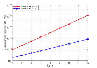
Fig. 2 shows the computational complexity of the proposed two methods versus with () (2, 10, 10). It verifies that as N increases, the computational complexity of the proposed CCT-SDP method and DT-SCA method increase. Meanwhile, it is obvious that the complexity of CCT-SDP method is far higher than that of DT-SCA method, which is consistent with our analysis of the complexity in previous sections.
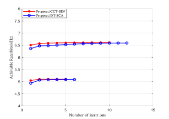
Fig. 3 verifies the convergence of the proposed two algorithms with 15dBm and 25dBm. When 15dBm, it needs about four iterations to be convergent for the proposed CCT-SDP and DT-SCA methods. In the case of 25dBm, the proposed two methods can come up to maximum rate within eight iterations. It is revealed that the proposed CCT-SDP and DT-SCA methods are convergent and feasible.
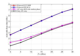
Fig. 4 depicts the achievable rate versus with (M, N, )= (2, 256, 30dBm). Obviously, the rate performance of the proposed CCT-SDP and DT-SCA methods increase as the transmit power at S increase. Since multipaths have been created with the aid of RIS, and beamforming matrix at AF relay and phase shifts at RIS have been optimized, the proposed two schemes can perform much better than a RIS-assisted AF relay network with random phase and a AF relay network without RIS. Moreover, the rate of DT-SCA method is slightly lower than that of CCT-SDP scheme in the whole region.
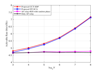
Fig. 5 shows the achievable rate versus the number of RIS elements with () (2, 30dBm, 30dBm). For small-scale RIS, the gap between the proposed two methods (i.e. CCT-SDP and DT-SCA) and two benchmark schemes (i.e. a RIS-assisted AF relay network with random phase and a AF relay network without RIS) is small. As the number of RIS elements increases, the rates of CCT-SDP and DT-SCA methods increase, which widen the gap gradually. For medium-scale and large-scale RIS, the gap between CCT-SDP and DT-SCA method is growing smaller. When 256, the rate of DT-SCA method is approximate to that of CCT-SDP method. Meanwhile, compared to the two benchmark schemes, a 50% rate gain can be obtained by the proposed two schemes.
VI Conclusion
In this paper, a RIS-aided AF relay wireless network was investigated. There were two AO methods based on the criterion of Max SNR proposed, one is CCT-SDP and the other is DT-SCA. Here, the beamforming matrix at AF relay and phase shifts matrices at RIS were jointly optimized for rate performance enhancement. From simulation, it was verified that the proposed CCT-SDP and DT-SCA schemes are convergent, which can obtain an apparent rate improvement compared to a RIS-assisted AF relay network with random phase and a AF relay network without RIS. Besides that, it was proved that the rate performance achieved by the low-complexity DT-SCA method is slightly lower than that of the high-performance CCT-SDP method.
References
- [1] F. Shu, Y. Teng, J. Li, M. Huang, W. Shi, J. Li, Y. Wu, and J. Wang, “Enhanced secrecy rate maximization for directional modulation networks via IRS,” IEEE Trans. Commun., vol. 69, no. 12, pp. 8388–8401, Dec. 2021.
- [2] Z. Tian, Z. Chen, M. Wang, Y. Jia, L. Dai, and S. Jin, “Reconfigurable intelligent surface empowered optimization for spectrum sharing: Scenarios and methods,” IEEE Trans. Veh. Technol., vol. 17, no. 2, pp. 74–82, June 2022.
- [3] Z. Chen, J. Tang, X. Y. Zhang, D. K. C. So, S. Jin, and K.-K. Wong, “Hybrid evolutionary-based sparse channel estimation for irs-assisted mmwave mimo systems,” IEEE Trans. Wireless Commun., vol. 21, no. 3, pp. 1586–1601, Mar. 2022.
- [4] Q. Wu and R. Zhang, “Intelligent reflecting surface enhanced wireless network via joint active and passive beamforming,” IEEE Trans. Wireless Commun., vol. 18, no. 11, pp. 5394–5409, Nov. 2019.
- [5] F. Shu, Y. Lu, Y. Chen, X. You, J. Wang, M. Wang, W. Sheng, and Q. Chen, “High-sum-rate beamformers for multi-pair two-way relay networks with amplify-and-forward relaying strategy,” Sci. China Inf. Sci., vol. 57, pp. 1–11, Feb. 2014.
- [6] X. Wang, F. Shu, W. Shi, X. Liang, R. Dong, J. Li, and J. Wang, “Beamforming design for IRS-aided decode-and-forward relay wireless network,” IEEE Trans. Green Commun. Netw., vol. 6, no. 1, pp. 198–207, Mar. 2022.
- [7] Q. Gu, D. Wu, X. Su, J. Jin, Y. Yuan, and J. Wang, “Performance comparisons between reconfigurable intelligent surface and full/half-duplex relays,” in IEEE 94th Veh. Technol. Conf. (VTC2021-Fall), Dec. 2021, pp. 01–06.
- [8] M. Wang, W. Duan, G. Zhang, M. Wen, J. Choi, and P.-H. Ho, “On the achievable capacity of cooperative NOMA networks: RIS or relay?” IEEE Wireless Commun. Lett., vol. 11, no. 8, pp. 1624–1628, Aug. 2022.
- [9] W. Jiang, B. Chen, J. Zhao, Z. Xiong, and Z. Ding, “Joint active and passive beamforming design for the IRS-assisted MIMOME-OFDM secure communications,” IEEE Trans. Veh. Technol., vol. 70, no. 10, pp. 10 369–10 381, Oct. 2021.
- [10] S. Hong, C. Pan, H. Ren, K. Wang, K. K. Chai, and A. Nallanathan, “Robust transmission design for intelligent reflecting surface-aided secure communication systems with imperfect cascaded CSI,” IEEE Trans. Wireless Commun., vol. 20, no. 4, pp. 2487–2501, Apr. 2021.
- [11] W. Shi, J. Li, G. Xia, Y. Wang, X. Zhou, Y. Zhang, and F. Shu, “Secure multigroup multicast communication systems via intelligent reflecting surface,” China Commun., vol. 18, no. 3, pp. 39–51, Mar. 2021.
- [12] X. Zhou, S. Yan, Q. Wu, F. Shu, and D. W. K. Ng, “Intelligent reflecting surface (IRS)-aided covert wireless communications with delay constraint,” IEEE Trans. Wireless Commun., vol. 21, no. 1, pp. 532–547, Jan. 2022.
- [13] B. Zheng, S. Lin, and R. Zhang, “Intelligent reflecting surface-aided LEO satellite communication: Cooperative passive beamforming and distributed channel estimation,” IEEE J. Sel. Areas Commun., vol. 40, no. 10, pp. 3057–3070, Oct. 2022.
- [14] J. Lee, W. Shin, and J. Lee, “Performance analysis of IRS-assisted LEO satellite communication systems,” in Int. Conf. Inf. and Commun. Technol. Conv. (ICTC), Dec. 2021, pp. 323–325.
- [15] W. Shi, X. Zhou, L. Jia, Y. Wu, F. Shu, and J. Wang, “Enhanced secure wireless information and power transfer via intelligent reflecting surface,” IEEE Commun. Lett., vol. 25, no. 4, pp. 1084–1088, Apr. 2021.
- [16] W. Jiang and H. D. Schotten, “Intelligent reflecting vehicle surface: A novel IRS paradigm for moving vehicular networks,” in IEEE Mil. Commun. Conf. (MILCOM), Jan. 2023, pp. 793–798.
- [17] F. Shu, X. Jiang, X. Liu, L. Xu, G. Xia, and J. Wang, “Precoding and transmit antenna subarray selection for secure hybrid spatial modulation,” IEEE Trans. Wireless Commun., vol. 20, no. 3, pp. 1903–1917, Mar. 2021.
- [18] F. Shu, L. Yang, X. Jiang, W. Cai, W. Shi, M. Huang, J. Wang, and X. You, “Beamforming and transmit power design for intelligent reconfigurable surface-aided secure spatial modulation,” IEEE J. Sel. Topics Signal Process., vol. 16, no. 5, pp. 933–949, Aug. 2022.
- [19] X. Wang, P. Zhang, F. Shu, W. Shi, and J. Wang, “Power allocation for irs-aided two-way decode-and-forward relay wireless network,” IEEE Trans. Veh. Technol., vol. 72, no. 1, pp. 1337–1342, Jan. 2023.
- [20] Q. Bie, Y. Liu, Y. Wang, X. Zhao, and X. Y. Zhang, “Deployment optimization of reconfigurable intelligent surface for relay systems,” IEEE Trans. Green Commun. Netw., vol. 6, no. 1, pp. 221–233, Mar. 2022.
- [21] W. Khalid, M. Shahjalal, and H. Yu, “Outage performance analysis of hybrid relay-reconfigurable intelligent surface networks,” in 27th Asia Pac. Conf. on Commun. (APCC), Nov. 2022, pp. 253–254.
- [22] Z. Abdullah, S. Kisseleff, K. Ntontin, W. A. Martins, S. Chatzinotas, and B. Ottersten, “Double-RIS communication with DF relaying for coverage extension: Is one relay enough?” in IEEE Int. Conf. Commun. (ICC), Aug. 2022, pp. 2639–2644.
- [23] G.-H. Li, D.-W. Yue, S.-N. Jin, and Q. Hu, “Hybrid double-RIS and DF-relay for outdoor-to-indoor communication,” IEEE Access, vol. 10, pp. 126 651–126 663, Dec. 2022.
- [24] M. Obeed and A. Chaaban, “Joint beamforming design for multiuser MISO downlink aided by a reconfigurable intelligent surface and a relay,” IEEE Trans. Wireless Commun., vol. 21, no. 10, pp. 8216–8229, Oct. 2022.
- [25] Z. Sun, X. Wang, S. Feng, X. Guan, F. Shu, and J. Wang, “Pilot optimization and channel estimation for two-way relaying network aided by IRS with finite discrete phase shifters,” IEEE Trans. Veh. Technol., pp. 1–6, 2023.
- [26] X. Guan, Q. Wu, and R. Zhang, “Joint power control and passive beamforming in IRS-assisted spectrum sharing,” IEEE Commun. Lett., vol. 24, no. 7, pp. 1553–1557, July 2020.