Capillary filling in microchannels with wall corrugations -
A comparative study of the Concus-Finn criterion by continuum, kinetic and atomistic approaches
Abstract
We study the impact of wall corrugations in microchannels on the process of capillary filling by means of three broadly used methods - Computational Fluid Dynamics (CFD), Lattice-Boltzmann Equations (LBE) and Molecular Dynamics (MD). The numerical results of these approaches are compared and tested against the Concus-Finn (CF) criterion, which predicts pinning of the contact line at rectangular ridges perpendicular to flow for contact angles . While for , (no flow) and (flow) all methods are found to produce data consistent with the CF criterion, at the numerical experiments provide different results. Whilst pinning of the liquid front is observed both in the LB and CFD simulations, MD simulations show that molecular fluctuations allow front propagation even above the critical value predicted by the deterministic CF criterion, thereby introducing a sensitivity to the obstacle height.
Dip. Fisica Universitá di Roma Tre Via della vasca navale 84, 00146 Roma, Italy]Dip. Fisica Universitá di Roma tre Roma, Italy D’Appolonia S.p.A. 00142 Rome, Italy]D’Appolonia S.p.A. 00142 Rome Italy Inorganic Chemistry and Physical Chemistry Department University of Food Technology, Maritza Blvd. 26, 4000 Plovdiv, Bulgaria]Inorganic Chemistry and Physical Chemistry Department University of Food Technology Maritza Blvd 26 4000 Plovdiv Bulgaria IAC–CNR, via dei Taurini 19, 00185, Roma, Italy]IAC–CNR 00185 Roma Italy Institute of Physical Chemistry, Bulgarian Academy of Sciences, 1113 Sofia, Bulgaria]Institute of Physical Chemistry Bulgarian Academy of Sciences 1113 Sofia Bulgaria D’Appolonia S.p.A. 00142 Rome, Italy]D’Appolonia S.p.A. 00142 Rome Italy IAC–CNR, va dei Taurini 19, 00185, Roma, Italy]IAC–CNR 00185 Roma Italy
1 Introduction
In the recent years, with the rapid technological progress in the production of micro- and nano-channels, the understanding of fluid flow on the nanoscale[1, 2] has become crucial for modern nanotechnology (such as the “lab on a chip” and related microfluidic devices) as well as for various applications of porous materials, flow in biomembranes, etc. A key problem is the description of fluid flow in narrow channels with wettable walls. Such channels are ubiquitous in cells and living matter but have been also successfully produced from synthetic materials in recent years[3]. Thus, planar nanochannels, fabricated by silicon-based technology, can provide an attractive configuration for fundamental studies like filling kinetics[4], hydrodynamics in confinement, and for molecular separation processes in biology[5]. Indeed, besides practical applications, microfluidics also raises a challenge to basic research since the continuum description of fluid flow goes under question whenever discreteness of matter comes into play, that is, at length scales comparable to the molecular size.
To gain insight into the transport mechanisms involved in fluid flows, many researchers have studied the problem using a variety of computer simulation methods, and most notably Computational Fluid Dynamics (CFD), Lattice-Boltzmann Equations (LBE), and Molecular Dynamics (MD) methods. The classical continuum theory based on Navier-Stokes (NS) equations assumes that state variables do not vary appreciably on a length scale comparable to the molecular free path. This conjecture has been challenged by both experiment[6] and the earliest MD computer simulations[7] which indicate the existence of significant density fluctuations of the liquid normal to the solid wall. Against expectations, however, some MD studies[8, 9] on Poiseulle flow demonstrated that the classical NS description may be used for modeling capillary flow in channels with diameter of several molecular sizes and greater, while this has been challenged by another study[10]. To these controversial results one should add data, produced by the LBE method[11] which has gained increased prominence in recent years due to its efficiency and proximity to the basic assumptions of the NS constitutive equations. Results from the LBE approach indicate that there are several microfluidic situations, in which molecular details, although non-negligible, can still be given a meso-scopic, rather than fully atomistic, representation, without affecting the basic physics [12, 13, 14, 15, 16, 17, 18]. On general grounds, this can be expected to be the case whenever molecular fluctuations do not play any major role. However, as the physics of micro/nanoflows progresses towards increasingly demanding standards, qualitative expectations need to be complemented and possibly tested against quantitative assessments.
In view of the diversity of methods and the plethora of controversial results from the computational modeling of flow in the sub-micrometer range, a test of the adequacy and reliability of the principal approaches is highly warranted. In the present investigation we perform such a test by comparing the results from three of the most broadly used methods - CFD, LBE, and MD - focusing on a generic case, the capillary filling of a wettable narrow channel by spontaneous imbibition of a simple fluid.
The aim of this comparative study is as follows: (i) we test the reliability of the three simulation methods with respect to the capillary filling of a wettable nanochannel, by comparing the results against the Lucas - Washburn (LW) theoretical prediction; (ii) we analyse the effect of the presence of an isolated corrugation on the flow dynamics and test the numerical results against the theoretical Concus-Finn criterion; (iii) the direct comparison between fluctuating (MD) and non-fluctuating (CFD and LB) approaches, permits to highlight the role of thermal fluctuations on the universality of the CF criterion.
2 Theoretical background
In a horizontal capillary under steady state conditions (i.e., in the absence of gravity and transient inertial effects), the capillary imbibition pressure is balanced by the viscous drag of the liquid. Simple analysis of this process leads to the Lucas - Washburn equation (LW)[19, 20] which relates the distance of penetration of the fluid front at time to the capillary size , the viscosity and surface tension of the liquid, and the static contact angle between the liquid and the capillary wall. If slip velocity and deviations from Poiseille flow are neglected, in the late asymptotic regime the distance travelled by the moving interface in the channel (having as initial coordinate) is given by
| (1) |
where denotes the height of the channel and the constant for a slit-like capillary. Equation 1 can be recast in dimensionless form as and , where , becoming:
| (2) |
It is apparent that in these dimensionless units, time-penetration depends only on the value of the contact angle , regardless of other fluid parameters and geometrical details. This facilitates the comparison between different simulation methods.
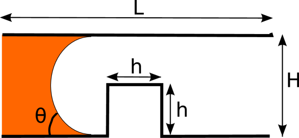
In this comparative study we explore capillary filling in the presence of topological obstacles (rectangular ridges) on the channel wall (1). Since capillary filling is mainly determined by the three-phase boundary (“contact line”) between liquid, wall and vapor, the motion of the contact line offers a much more stringent test of the various simulation methods and offers a possibility to assess their shortcomings and advantages. A key problem in this regard is the pinning of the contact line, due to a geometric singularity in the meniscus stability, like the presence of obstacles whose sides make an angle with respect to the wall, broadly known as Concus-Finn condition [21, 22, 23]. According to the Concus-Finn criterion, there is no filling due to meniscus instability, provided the contact angle fulfills the following condition:
| (3) |
For a rectangular obstacle, this means that a contact line will be pinned at its trailing edge, once , regardless of the obstacle height. While this condition follows from the detailed mathematical analysis[21] of the liquid surface stability, in fact it goes back to the thermodynamic foundations of wetting, as established in the early works of Gibbs[24]. The possibility for capillary driven flow is of major importance for numerous applications, e.g., modern fuel cells[25], therefore it is not surprising that this criterion has been tested even in space experiments on the Shuttle-Mir complex.
3 Modelling microfluids: from continuum mechanics to molecular dynamics
Currently, intensive efforts to get deeper insight and understanding of flow in microchannels are carried out by researchers using a variety of computer modeling approaches. In principle, continuum fluid mechanics provides the most economical description of microflows. However, this approach fails to describe a series of phenomena, such as near-wall slip-flow, in which the continuum assumption goes under question due to the onset of molecular effects, especially near solid walls. Molecular Dynamics provides a high degree of physical fidelity, at the price, however, of a very susbtantial computational burden. The lattice kinetic approach is well positioned to offer a good compromise between the physical realism of molecular dynamics and the computational efficiency of continuum mechanics [26, 27]. The lattice kinetic approach is finding increasing applications to microfluidic problems, as it permits to handle fluid-wall interactions at a more microscopic level than the Navier-Stokes equations, while simultaneously reaching up to much larger scales than Molecular-Dynamics [12, 28, 29, 30]. However, the LB approach is subject to a number of limitations, such as the existence of spurious currents near curved interfaces, as well as enhanced evaporation/condensation effects due to the finite-width of the interface [31]. Ideally, one would combine the three methods within a synergistic multiscale procedure, using each of them wherever/whenever appropriate, in different regions of the microflow. Various two-level (continuum-MD, LB-MD and continuum-LB), are already available in the literature [32], while, to the best of our knowledge, three-level coupling are just beginning to appear [33]. A detailed and comparative assessment of merits and downsides of the three levels of description, is therefore of great importance to the ultimate goal of developing efficient and robust multiscale coupling methods for complex microfluidic flows. In this work, we shall present a comparative study of capillary filling in the presence of wall corrugations, using all of the three methods mentioned above, namely a finite-volume CFD software package, a LB model with non-ideal fluid interactions, and a MD computer program. Since all of these methods are by now standard, in the following we shall provide just a cursory description, leaving the details to the vaste literature on the subject.
3.1 Computational Fluid Dynamics
Our CFD approach is based on the CFD-ACE+ software package (release 2008), as a multiphysics commercial tool including geometry modeling, grid generation and results visualization [34]. The spontaneous capillary filling in micro/nano channels is reproduced by means of the VOF (Volume of Fluid) scheme, based on the hypotheses of incompressibility, no-interpenetration and negligible localized relative slip of the two fluids in contact. In order to describe the transport of the volume fraction of one of the two fluids in each cell ( thus ranging from 0 to 1), the Navier-Stokes equations for the fluid velocity are augmented with a scalar transport equation for the volume fraction:
| (4) |
where is time, is the standard spatial gradient operator, and is the velocity vector of the fluid. The composition of the two fluids in the mixture determines for each computational cell the averaged value of physical properties such as density and viscosity. Any volume-specific quantity is evaluated in accordance with the following expression:
| (5) |
where is the volume-averaged quantity, (resp. ) is the value of the property for one liquid (resp. gas). However, being the averaged volume fraction of fluid in each cell, the definition of the interface between the two fluids in that cell is not unique and must be dynamically reconstructed throughout the simulation. In CFD-ACE+, this is accomplished through an upwind scheme with PLIC (Piecewise Linear Interface Construction method [35, 36]), taking into account surface tension to determine accurately the interface curvature. As to boundary conditions, a zero static pressure is imposed at both inlet (liquid only) and outlet (gas only). At the initial time both fluids are at rest, with a short portion of the channel at the inlet filled with liquid. This specific configuration allows the liquid-vapour interface to assume the curvature corresponding to the hydrophilic partial wetting condition imposed at walls through the contact angle , thus generating the capillary pressure that drives the fluid motion. The CFD simulation set-up consists of a straight channel with a height nm and overall length m. At the bottom wall, a squared post, of side and height nm, is located. The computational domain has been discretized with a squared structured non-uniform grid consisting of cells and nodes.
3.2 Lattice Boltzmann method for multiphase flows
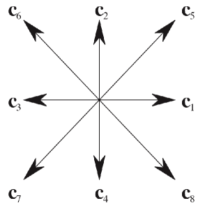
The Lattice Boltzmann (LB) method is based on a minimal form of the Boltzmann kinetic equation describing the time evolution of discrete particle distribution function , denoting the probability of finding a particle at lattice site and time moving along the lattice vector ( 2), where the index labels the discrete directions of motion.
In mathematical terms [27], the LB equation reads as follows: [37]
| (6) |
where is the fluid density, is the fluid velocity and labels the the nine-speed, two-dimensional model [27]. The second term on the right hand side is a model collision operator , describing the relaxation towards a local equilibrium on a time scale . Finally, describes the effect of external/internal forces on the discrete particle distribution. The macroscopic density and momentum are obtained as weighted averages of discrete distributions: [27]
| (7) |
For the case of a two-phase fluid, the interparticle force reads as follows:
| (8) |
Here is the pseudo-potential functional, describing the fluid-fluid interactions triggered by inhomogeneities of the density profile, and is the strength of the coupling (see [11, 38] for details). Finally, , where are the standard weights of the nine-speed two-dimensional lattice 2DQ9 [27] and is the sound speed in lattice units. Besides introducing a non-ideal excess pressure , the model also provides a surface tension , where is the drop of the pseudo-potential across the interface of width . By tuning the value of the pseudo-potential at the wall , this approach allows to define a static contact angle, spanning the full range of values [39].
As to the boundary conditions, the standard bounce-back rule is imposed: any flux of particles that hits a boundary simply reverses its velocity so that the average velocity at the boundary is automatically zero. This rule can be shown to yield no-slip boundary conditions up to second order in the Knudsen number in the hydrodynamic limit of single phase flows.
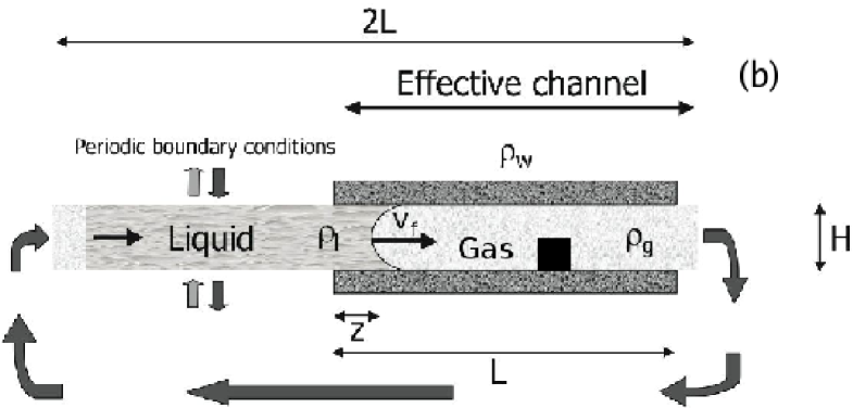
In this work we consider a channel composed of two parallel plates separated by a distance , where is the space discretization unit. This two-dimensional geometry, with length , is divided in two regions, as shown in 3. The left part has top and bottom periodic boundary conditions, so as to support a perfectly flat gas-liquid interface, mimicking a “infinite reservoir”. The actual capillary channel resides on the right half, of length . The top and bottom boundary conditions are those of a solid wall, with a given contact angle . Periodic boundary conditions are also imposed at the west and east sides. The squared obstacle, of side , is placed on the lower wall.
3.3 Molecular Dynamics
During the last few decades Molecular Dynamics has proved to be one of the most broadly used simulation techniques, capable of reproducing many details of macroscopic fluid dynamics. It has been extensively used to study dynamic wetting problems and to shed more light on the molecular processes close to the contact line region [40, 41]. An appealing feature of MD (e.g., compared with Monte Carlo or molecular statics) is that it follows the actual dynamical evolution of the system.
We perform MD simulation of a simple generic model on a coarse-grained level. In our MD simulation, see Fig. 4, the fluid particles interact with each other through a Lennard-Jones (LJ) potential,
| (9) |
where and . The capillary walls are represented by particles forming a triangular lattice with spacing in units of the liquid atom diameter . The wall atoms may fluctuate around their equilibrium positions, subject to a finitely extensible non-linear elastic (FENE) potential
| (10) |
with and where denotes the Boltzmann constant and is the temperature of the system; is the distance between the particle and the virtual point which represents its equilibrium position in the wall structure. The FENE-potential acts like an elastic string between the wall-particles and their equilibrium positions in the lattice and keeps the structure of the wall densely-packed hexagonal. In addition, the wall particles interact with each other via a LJ potential with and . This choice of interactions guarantees no penetration of liquid through the wall, and at the same time the mobility of the wall particles corresponds to the system temperature.
Molecules are advanced in time via the velocity-Verlet algorithm with integration time step where is the basic time-unit and we have taken particle mass and . The temperature is maintained by a Dissipative-Particle-Dynamics (DPD) thermostat, with friction parameter , thermostat cutoff and step-function-like weight functions [42, 43]. Fluid properties and flow boundary conditions arise then as a consequence of the collision dynamics and the local friction controlled by the DPD thermostat. An advantage of the DPD method in comparison with other MD schemes is that the local momentum is conserved, so that the hydrodynamic behavior of the liquid at large scales is correctly reproduced.
It is worth emphasizing that all contact angles , used in the simulations, have been determined by measuring the mean static contact angle of a sessile meniscus in a slit, formed by two parallel atomistic walls for a few given liquid -wall interactions . Specific contact angles are then chosen by interpolation between the relevant values of . Therefore, the actual value of the contact angle when the fluid front is located at an obstacle edge, for instance, may incidentally deviate from the nominal value of . A recent MD study [44] has shown that the LW-law (Eq.(1)), holds almost quantitatively down to nanoscale tube diameters. In this study we use an obstacle shaped as a rectangular ridge which runs perpendicular to the flow direction in the slit and has the same atomic composition as that of the slit walls. The height and width of the ridge are chosen as so that the obstacle height takes half of the slit thickness.
4 Numerical results
We have performed simulations of spontaneous capillary filling in presence of a squared obstacle, for each of the three computational methods described above. The test case is the same: the filling of a channel of height with a squared post of side . In LB and MD, the post is placed at the central position on the bottom wall(1), at a distance and from the inlet, respectively, due to computational costs. Since the LW equation does not depend on the channel length, this is not a limiting factor for the present study (see below). Since the inertial transient with the CFD method is much longer than the estimated inertial time, as shown also in 5, in this case the channel length has been taken , so as to guarantee that the front meets the post when the asymptotic regime is attained.
We have performed a series of four simulations (for each method), varying the contact angle from to . The specific values of the physical parameters for each simulation method are reported in Table 1.
| Parameter | CFD value | LB value | MD value |
|---|---|---|---|
| Channel height (m) | |||
| Water density (kg/m3) | |||
| Water kinematic viscosity (m2/s) | |||
| Water dynamic viscosity (kg/(m s)) | |||
| Liquid/gas surface tension (N/m) | |||
| Vapour density (kg/m |
Some comments are in order. By construction, the CFD approach is able to reproduce exactly all the physical properties of the flow. On the other hand, both LB and MD show some discrepancies in the value of the surface tension and vapour density. However, these discrepancies have been found to be irrelevant to the purpose of investigating the macroscopic features of capillary imbibition [44, 45]
As is well known, depending on the value of the contact angle , two scenarios may appear according to the Gibbs, or Concus Finn criterion [21, 22, 23]: a) for small contact angles the front is able to climb the obstacle, walk on it, and eventually pass it; b) for large contact angles the front climbs the obstacle, but pins at its back edge, thus stopping the fluid motion. We wish to emphasize that the Concus-Finn, or Gibbs, criterion is based upon thermodynamic arguments and, consequently, it has been rigourously proven only at a macroscopic level.
4.1 Recovering the Lucas-Washburn regime
As is well known, the Lucas-Washburn asymptotic regime sets in once inertial effects die out and steady propagation results from the sole balance between capillary drive and dissipation. During the transient regime, the dynamic contact angle, which depends on the front speed itself, changes in time until its static value is attained [46, 47].
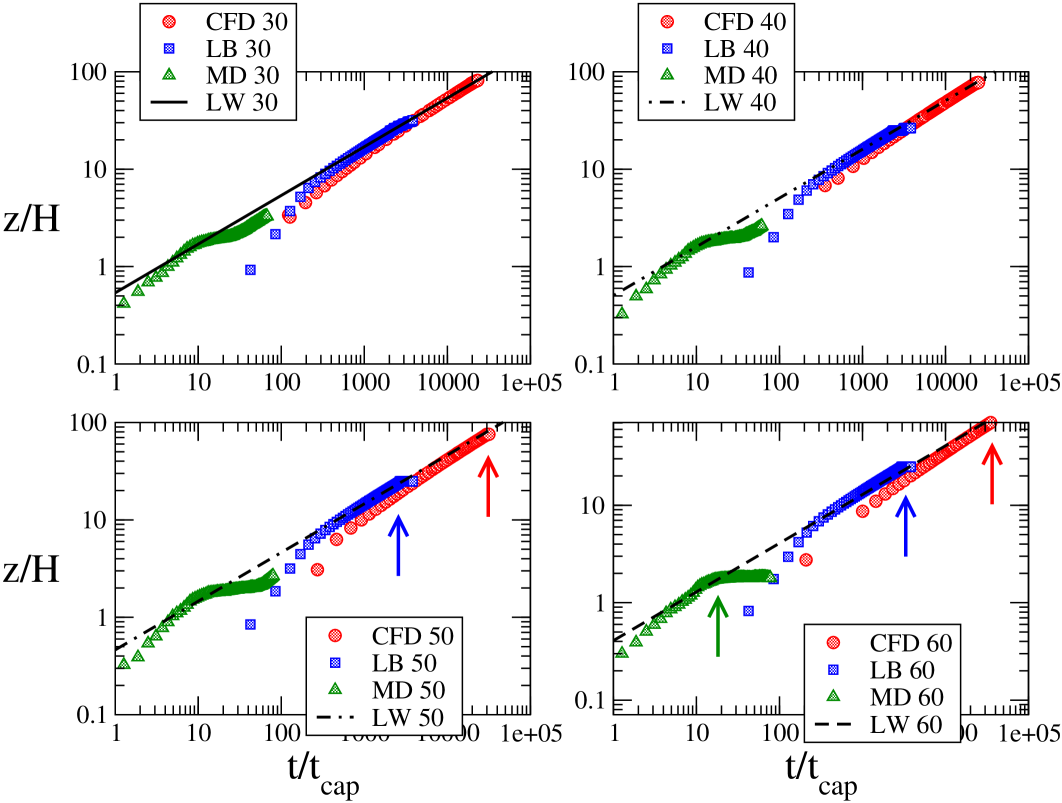
In 4, the time evolution of the centerline ( front position is reported as a function of time, and compared with the dimensionless LW-law Eq. (2). As one can see, all three methods exhibit satisfactory agreement with the theoretical LW prediction, although on a different range of time-scales. This is due to the different values of the parameters used in each method, and particularly, to the fact that the MD capillary speed is times higher than in the other methods. Indeed, it should be noted that the LW asymptotic solution sets in after a typical transient time of the order of , or in units of capillary times, . Based on the data in Table I, one can readily check that for LB and CFD, and for MD. It is therefore possible to appreciate the anomalous transient in the CFD case, see 4, which is of the order . However, since CFD and LB simulations last over capillary times, and MD simulations last about capillary times, before reaching the obstacle, the superposition with the LW regime is free from transient phenomena.
4.2 Front morphology while crossing the obstacle
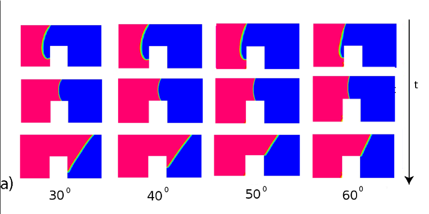
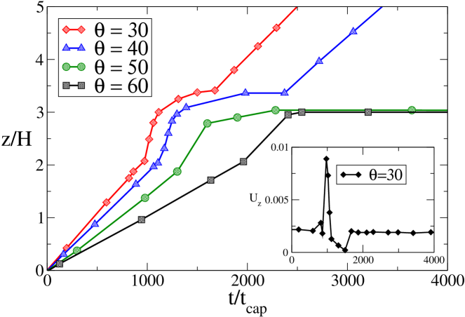
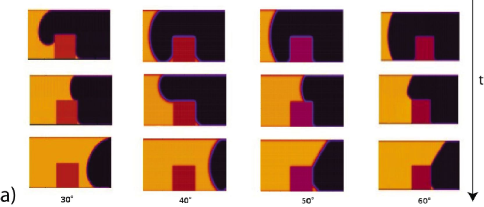
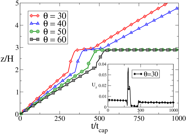
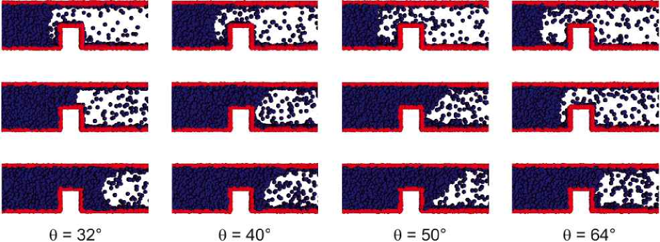
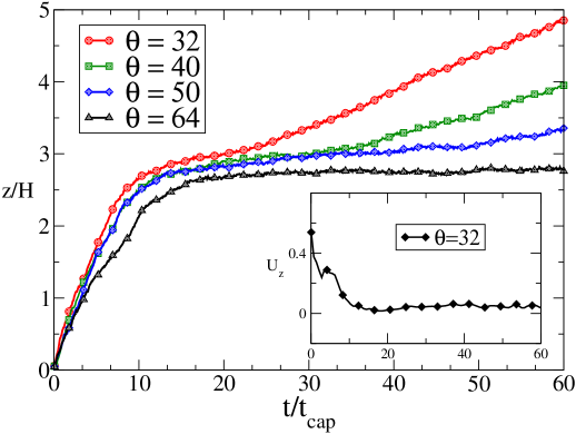
In 5, 6 and 7, snapshots of the fluid front during the surmounting of the obstacle are reported for the three simulation methods (the figures report density contours). As one can see, the front dynamics and morphology are strongly affected by the presence of the obstacle: the liquid impinging on the obstacle must adjust to a degrees discontinuity of the contact angle, which is clearly causing a significant deformation of the front, before the static value is recovered again on the flat-top surface of the obstacle. These changes of shape are well visible in figures 5 and 6, for both CFD and LB. The case of MD is less clear-cut, due to the absence of a well-defined interface and to molecular fluctuations. Indeed, although the fluid meniscus is clearly visible, its surface appears rough and strongly fluctuating in time. From 7 one can see that some atoms evaporate from the liquid and overcome the slit. Moreover, long before the fluid meniscus has passed the obstacle, vapor condensation and partial filling of the wedge, formed by the rear wall of the ridge and the slit wall, take place (see also 7a). Since fluid imbibition in a capillary is accompanied by the faster motion of a precursor film far ahead of the meniscus [49, 50, 48], it is also conceivable that the wedge is filled by this atomically thin precursor. Since the meniscus position at time is difficult to locate precisely, we rather measure the volume of the fluid in the capillary which is readily obtained by the total number of fluid atoms, residing at time in the slit during the filling process. For an incompressible fluid, this volume is directly proportional to the distance , travelled by the fluid front at time . The curve giving is shown in 7b for several values of the contact angle, . The shape changes also entail a substantial change of the front speed, as well documented in 5b, 6b and 7b , from which the front speed can be read off simply as the slope of the curves reporting the front position as a function of time. These figures show evidence of a significant acceleration of the front (centerline position ) in the climbing stage, followed by a deceleration in the stage where the front is approaching the rear corner, where the chance/risk of pinning is highest. Here the fate of the front becomes critical. According to the CF analysis, if the contact angle is below , there is enough drive from the upper wall to pull the front away from the rear edge of the obstacle. Otherwise, the front stops moving.
The CFD and LB simulations confirm this picture, showing evidence of pinning only for the two angles above . More precisely, they show a significant front acceleration in the climbing stage, followed by a coasting period, once the rear edge is reached. For and , the coasting period exhibits a finite lifetime, after which the front regains its motion. For and , the coasting period does not seem to come to an end (within the simulation time), and the front is pinned. After the obstacle, the (unpinned) front is slowed down, as one can appreciate from the slightly reduced slope of the front dynamics, see 5b (only for ) and 6b.
The MD simulations, on the other hand, tell a different story, in that even at , the front proves capable of overcoming the obstacle, although with a drastically reduced speed. Note that, while both CFD and LB show evidence of a strong front acceleration as they approach the obstacle, MD simply shows a monotonic deceleration. This is due to the fact that while in CFD and LB simulations we measure the distance travelled by the interface midpoint, as already pointed out, MD measures the total volume of the fluid in the capillary.
Given the qualitatively different outcome of CFD(LB) versus MD simulations at , we next discuss the dependence of the filling dynamics on the different contact angles, case by case.
-
•
Contact angles and
As already mentioned, in these cases, all three methods give the same qualitative outcome: in proximity of the ridge, the front deforms in response to the geometrical discontinuity, climbs up the obstacle and walks over its top. Once the rear-edge is reached, the bottom end of the front pins at the corner, and keeps moving on the top wall. Then, according to the CF criterion, the front overcomes the obstacle and completely fills up the entire channel. Manifestly, the standard versus relationship, described by the LW-law (1) is strongly violated in the vicinity of the obstacle. After overcoming the obstacle, the usual LW regime is recovered, although after a transitional period of time, which depends on the wettability [17], and with a reduced velocity. In particular, in all cases, the front is slowed down right after passing the obstacle, see 5b, 6b and 7b. However, at , the asymptotic behaviour is quite different for the three methods: (i) In CFD simulations, 5b, after a short transient time, the velocity basically regains the initial value before passing the obstacle. (ii) LB shows a similar behaviour, with only a slight reduction of the front velocity after passing the obstacle. (iii) in MD, however, the front undergoes a substantial velocity decrease.This might be due to the details of the fluid-solid interaction during the obstacle surmounting (in which the contact angle is bound to undergo drastic changes), as well as to the different time-scales. A detailed analysis of this effect shall be deferred to a future study.
-
•
Contact angle
In this case, while results from CFD and LB confirm the CF criterion, MD simulations show a different behaviour for the front motion: interestingly, the Concus-Finn (Gibbs) criterion for contact line pinning at the edge of the ridge is found to break down. Indeed, for , the fluid front overcomes the obstacle in manifest violation of the Concus-Finn criterion. In order to vividly explain this feature, we show in 8 the snapshots and in video 1 and 2 the movie of the front dynamics, respectively for the cases . These observations suggest that, on the nanoscale, the overcoming of topological obstacles is strongly affected by interface fluctuations, thus undermining the deterministic nature of the imbibition process. Indeed, both the CFD and LB method work in absence of fluctuations, and this would explain the difference with MD simulations. The problem of contact line pinning during capillary imbibition acquires thus a stochastic character and is most probably governed by the size of the obstacles around the CF critical point. In fact, depending on the height of the ridge obstacle, a coalescence of the pinned meniscus with the molecules ahead of the obstacle, in the vicinity of the edge, may occur at later times. -
•
Contact angle
Again, in this case all the three methods give the same result: the front deforms, climbs the obstacle, walks on its top, but pins at the back edge and definitely stops moving.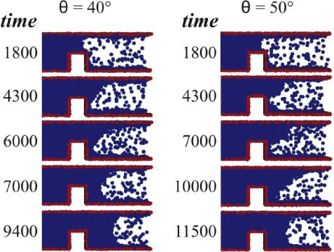
Figure 8: Snapshots from MD simulations with (on the left) and for (on the right). It is clearly seen that for both values of the contact angle the front overcomes the obstacle, although at different times. This shows that the Concus-Finn criterion is violated in the case with . 4.3 Further discussion
In order to gain a better understanding of the previous results, and particularly of the violation of the CF criterion for mildly super-critical angles in MD simulations, additional runs have been performed. More precisely, we have run MD simulations at with a taller obstacle, , in order to inspect whether the front is still capable of surmounting the obstacle in violation of the CF criterion (in this case, the total slit height was correspondingly increased, so as to leave the same clearance above the obstacle as in the previous simulations). Moreover, we have also run additional CFD and MD simulations at with shorter obstacles, , in order to inspect whether even CFD(LB) would show violations of the CF criterion upon reducing the obstacle size. The main outcome is as follows: MD simulations with do show front pinning, indicating that violations of the CF criterion disappear once the obstacle is made sufficiently tall (see Fig. 9). This corroborates our previous conjecture of a (Arrehnius-like?) dependence of the CF criterion on the obstacle height, in the presence of molecular fluctuations. At the same time, CFD and LB simulations with at keep showing evidence of pinning, thereby lending further support to the idea that the CF criterion remains insensitive to obstacle size, so long as molecular fluctuations can be neglected.
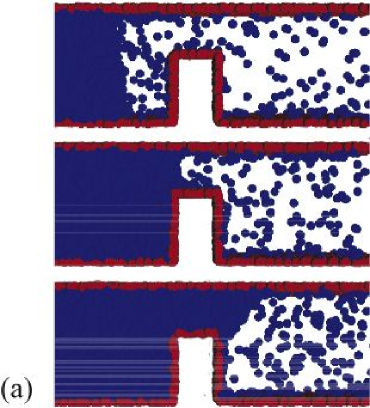
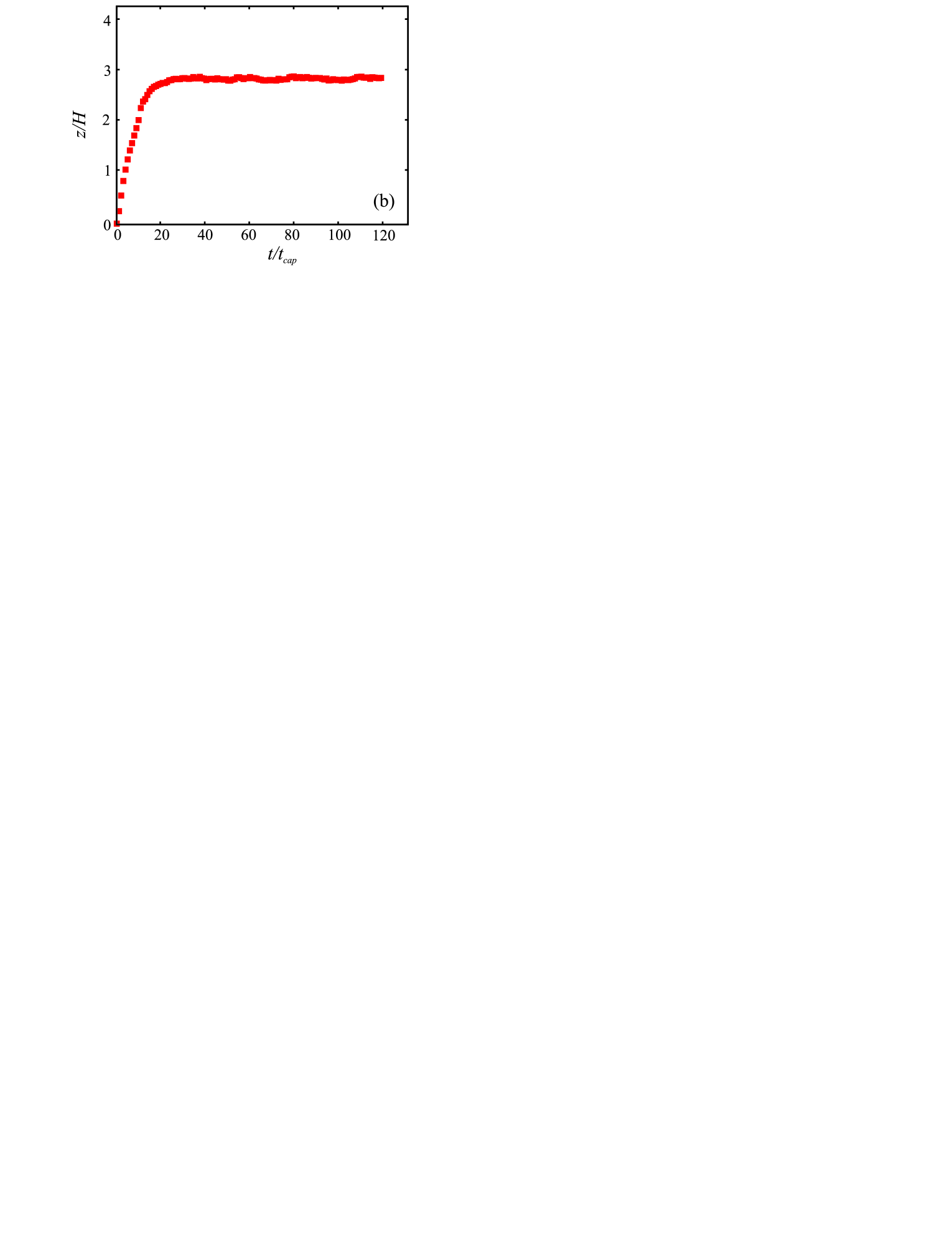
Figure 9: Snapshots (a) and centerline front coordinate (b), from MD simulations with and . Unlike the same case with , the front is now pinned in accordance with the CF criterion. Before concluding, a few words of caution should be spent on the fact that, being diffuse-interface methods, both CFD and LB propagate a finite-width interface. As a result, one may wonder whether and to what extent finite-width effects could interfere with the physics of post surmounting. Indeed, as shown in previous studies by these and other authors ([45, 13]), finite interface width eventually leads to mild deviations from the LW law. However, they do not affect the qualitative outcome of a pinning/no-pinning test, unless the interface width becomes comparable to the characteristic obstacle width. Both CFD and LB simulations are visibly far from this critical limit, which is why we are confident that the qualitative conclusions of the present work are not significantly affected by finite-width effects. One may wonder whether such deviations might be paralleled to the effect of molecular fluctuations. To this regard, it is worth underlining that such a parallel has to be taken very cautiously, since molecular fluctuations stem from the microscopic physics of the problem, while finite-width effects are due to a lack of numerical resolution. Sometimes a mapping between the two can be established, but this can by no means be taken as a general rule. Finally, another potential source of discrepancy between CFD(LB) and MD is the fact that the latter allows slip motion while CFD and LB (in this set up) do not. Although any solid statement on the effect of slip flow on the dynamics of post surmounting must necessarily be deferred to a detailed quantitative analysis, we observe that due to the weakness of inertial effects, hydrodynamic boundary conditions have little or no effect, on the dynamics/energetics of the obstacle surmounting.
This is confirmed by the fact that slip flow effects should manifest through visible deviations from the LW regime, of which we have no evidence, at least in the parameter regime investigated in this work. This situation can drastically change in the presence of superhydrophobic effects, although we shall not be concerned with these problems in the present work.
5 Conclusions
Summarizing, we have studied the effect of geometrical obstacles in microchannels on the process of capillary filling, by means of three distinct simulation methods - Computational Fluid Dynamics (CFD), Lattice-Boltzmann Equations (LBE) and Molecular Dynamics (MD). The numerical results of these approaches have been compared and tested against the Concus-Finn (CF) criterion, which predicts pinning of the contact line at rectangular ridges perpendicular to flow for contact angles . While for (flow), and (no flow) all methods are found to produce data consistent with the CF criterion, at the numerical experiments provide different outcomes. While pinning of the liquid front is observed in both LB and CFD simulations, the MD simulations show that the moving meniscus overcomes the obstacle and the filling goes on, for a sufficiently small obstacle. This result indicates that the macroscopic picture underlying the CF criterion and hydrodynamic approach needs to be amended near the critical angle. Furthermore, while in CFD and LB simulations the front re-emerges from the obstace surmounting with a nearly unchanged velocity, in the MD case the post-surmounting velocity appears considerably reduced. These results suggest that, away from the critical value , the issue of front-pinning in a corrugated channel can be quantitatively described by a kinetic Boltzmann approach or by the macroscopic CFD method.
While the CFD software used in this work is well-suited to handle complex geometries, it also shows some physical and computational limitations, namely anomalous-long transients and the need of a large computational grid to assure the required accuracy, which entails a correspondingly long computational time, much closer to the MD requirements than to the LB ones. In the vicinity of the critical angle, the motion of the front exhibits a strong sensitivity to molecular fluctuations which cannot be accounted for by standard (non-fluctuating) LB methods, let alone continuum methods. In particular, the MD simulations show that molecular fluctuations allow front propagation slightly above the critical value predicted by the deterministic CF criterion, thereby introducing a sensitivity to the obstacle height (the CF criterion is restored for sufficiently tall obstacles). On the basis of the present results, it would be indeed of interest to explore whether fluctuating hydrodynamic methods, either in the form of stochastic hydrodynamics or fluctuating LB, would prove capable of reproducing the results of MD simulations [51]. Whether the probability of "tunnelling" to the deterministically forbidden region shows an Arrehnius-like dependence on the obstacle height, stands as an interesting topic for future research.
The authors thank the support from the project "INFLUS", NMP-031980 of the VI-th FW programme of the EC.
References
- [1] Drake, J. M.; Klafter, J; Phys. Today 1990, 43, 46.
- [2] Meller, A; J. Phys. Condens. Matter 2003, 15, R581.
- [3] Alvine, K. J.; Shpyrko, O. G.; Pershan, P. S.; Shin, K; Russell, T. P.; Phys. Rev. Lett. 2006, 97, 175503
- [4] Haneveld, J.; Tas, N. R.; Brunets, N.; Jansen, H. V.; Elwenspoek, M.; J. Appl. Physics, 2008, 104, 014309.
- [5] Han, J.; Craighead, H. G.; Science 2000, 288, 1026.
- [6] Cheng, L.; Fenter, P.; Nagy,K. L.; Schlegel, M. L.; Sturchio, N. C.; Phys. Rev. Lett. 2001, 87, 156103.
- [7] Cieplak, M.; Koplik, J.; Banavar, J. R.; Phys. Rev. Lett, 2001, 86, 803.
- [8] Bitsanis, I.; Vanderlick, T. K.; Tirrell, M.; Davis, H. T.; J.Chem. Phys., 1998, 89, 3152.
- [9] Travis, K. P.; Todd, B. D.; Evans, D. J; Phys. Rev. E , 1997, 55, 4288.
- [10] Travis, K. P.; Gubbins, K. E.; J. Chem. Phys. 2000, 112, 1984.
- [11] Shan, X.; Chen, H.; Phys. Rev. E 1993, 47, 1815.
- [12] Sbragaglia M.; Benzi, R.; Biferale, L.; Succi, S.; Toschi F.; PRL 2006, 97 , 204503
- [13] Kusumaatmaja, H.; Pooley, C. M.; Girardo, S.; Pisignano, D.; Yeomans, J. M.; Phys. Rev. E2008 77, 067301.
- [14] Kuksenok O.;Jasnow, D.; Yeomans, J.; Balazs, A. C.; Phys. Rev. Letters 2003, 91, 108303.
- [15] Ansumali,S.;Frouzakis, C.E.; Karlin, I. V.; Boulouchos, K. B.;Physica A 2006 359, 289 .
- [16] Dupin, M. M.; Halliday, I.; Care C. M.; Physical Review E 2006 73, 055701
- [17] Chibbaro S., Biferale L, Binder K, Dimitrov D, Diotallevi F., Milchev A, and Succi S JSTAT 2009 P06007 arXiv:0901.0677v2
- [18] Diotallevi, F.; Biferale, L.; Chibbaro, S.; Puglisi, A.; Succi, S.; Phys. Rev. E 2008, 78, 036035.
- [19] Lucas, R. Kolloid Z.,1918, 23, 15.
- [20] Washburn, E. W.; Phys. Rev. 1923, 17, 273.
- [21] Concus, P.; Finn, R.; Appl. Math. Sci. 1969, 63, 292.
- [22] Concus, P.; Finn, R.; Acta Math.1974, 132, 177;
- [23] Finn, R,; Manuscripta Math. 1979, 28, 1.
- [24] Gibbs, J. W.; Scientiic papers 1906,1961, Dover, New York;
- [25] Metz, T.; Viertel, J.; Müller, C.; Kerzenmacher, S.; Paust, N.; Zengerle R.; Koltay, P.; J. Micromech. Microeng. 2008 18 104007.
- [26] Succi, S.; Eur. Phys. J. B. 2008, 64, 471.
- [27] Wolf-Gladrow, D.; Lattice-Gas Cellular Automata And Lattice Boltzmann Models 2000 (Springer, New York)
- [28] M.R Swift, W.R. Osborn, J.M. Yeomans, Phys. Rev. Lett. 75 (1995) 830.
- [29] J. Harting, C. Kunert, H.J. Herrmann, Europhys. Lett. 75 (2006) 328.
- [30] Popescu, S Dietrich, and G Oshanin, J. Phys.: Condens. Matter 17 4189 (2005)
- [31] Diotallevi, F; Biferale, L.; Chibbaro, S.; Pontrelli, G.; Succi, S.; Toschi F.; Eur. Phys. J. ST, 171, 237, (2009). arXiv : 0801.4223.
- [32] AG. Bird, Molecular Gas Dynamics and the Direct Simulation of Gas Flows, Claredon, Oxford 1994
- [33] Praprotnik, M.; Delgado-Buscalioni, R.; Kremer, K.; J. Chem. Phys. 2008,128, 114110.
- [34] ESI CFD Inc., CFD-ACE+ V2008 Modules Manual,Vol.2.
- [35] Kothe, D.B.; Rider, W.J.; Mosso, S.J.; Brock, J.S.; AIAA Paper, 1996 96-0859.
- [36] Rider, W.J.; Kothe, D.B.; Mosso, S.J.; Cerrutti, J.H.; Hochstein, J.I.; AIAA Paper 1995 95-0699.
- [37] Benzi, R.; Succi, S.; Vergassola, M.; Phys. Rep. 1992, 222, 145.
- [38] Sbragaglia, M.; Benzi, R.; Biferale, L.; Succi, S.; Sugiyama K.; Toschi, F.; Phys. Rev. E 2007,75 026702.
- [39] Kang, Q.; Zhang, D.; Chen, S.; Phys. Fluids 200214, 3203.
- [40] Thompson, P. A.; Robins, M. O.; Phys. Rev. Lett.,1989, 63, 766.
- [41] Gentner, F.; Ogonowski, G.; De Coninck, J.; Langmuir 2003,19, 3996.
- [42] Hoogerbrugge P. J.; Koelman, J. M.; Europhys. Lett., 1992,19, 155.
- [43] Allen M. P.; Tildesley, D. J.; Computer Simulation of Liquids, 1987, Clarendon Press, Oxford .
- [44] Dimitrov, D.; Milchev, A.; Binder, K.; Phys. Rev. Lett., 2007, 99, 054501.
- [45] Diotallevi, F; Biferale, L.; Chibbaro, S.; Lamura, A.; Pontrelli, G.; Sbragaglia, M.; Succi, S.; Toschi F.; Eur. Phys. J. ST, 166, 111, (2009).
- [46] Martic G. et al; Langmuir 2002, 18, 7971.
- [47] Quere D. et al; Europhys. lett. 1997, 39, 533.
- [48] Chibbaro, S.; Biferale, L.; Diotallevi, F.; Succi, S; Binder, K.; Dimitrov, D.; Milchev, A.; Girardo, S.; Pisignano, D.; EPL 208, 84 44003.
- [49] D. Bonn, J. Eggers, J. Indekeu, J. Meunier, E. Rolley, Rev. Mod. Phys 2009, 81, 739 .
- [50] H. Pirouz Kavehpour, Ben Ovryn, and Gareth H. McKinley, Phys. Rev. Lett. 91, 196104 (2003).
- [51] M. Moseler et al., Science, 2000, 289, 1165.