XX Month, XXXX \reviseddateXX Month, XXXX \accepteddateXX Month, XXXX \publisheddateXX Month, XXXX \currentdateXX Month, XXXX \doiinfoOJIM.2022.1234567
CORRESPONDING AUTHOR: M. Salman Asif (e-mail: sasif@ucr.edu). \authornoteThis work was supported in part by National Science Foundation (NSF) grants CCF-2046293 and CMMI-2133084.
Coded Illumination for 3D Lensless Imaging
Abstract
Mask-based lensless cameras offer a novel design for imaging systems by replacing the lens in a conventional camera with a layer of coded mask. Each pixel of the lensless camera encodes the information of the entire 3D scene. Existing methods for 3D reconstruction from lensless measurements suffer from poor spatial and depth resolution. This is partially due to the system ill conditioning that arises because the point-spread functions (PSFs) from different depth planes are very similar. In this paper, we propose to capture multiple measurements of the scene under a sequence of coded illumination patterns to improve the 3D image reconstruction quality. In addition, we put the illumination source at a distance away from the camera. With such baseline distance between the lensless camera and illumination source, the camera observes a slice of the 3D volume, and the PSF of each depth plane becomes more resolvable from each other. We present simulation results along with experimental results with a camera prototype to demonstrate the effectiveness of our approach.
3D reconstruction, coded illumination, mask-based lensless cameras
1 Introduction
Lensless cameras provide novel designs for extreme imaging conditions that require small, thin form factor, large field-of-view, or large-area sensors [1, 2, 3, 4]. Compared to conventional lens-based cameras, lensless cameras are flat, thin, light-weight, and geometry flexible. Depth estimation with lensless imaging has been a challenging problem [3, 5, 6]. The primary reason is that the sensor responses for different depth planes have small differences, which makes the 3D reconstruction an ill-conditioned problem.
In this paper, we propose a new method that combines coded illumination with mask-based lensless cameras (such as FlatCam[1]) to improve the quality of recovered 3D scenes. We project a sequence of coded illumination patterns onto the 3D scene and capture multiple frames of lensless measurements. We then solve an inverse problem to recover the 3D scene volume using all the coded measurements. Coded illumination-based measurements provide a better-conditioned system and improve the quality of 3D reconstruction. The illumination source is separated from the camera by a baseline distance, which ensures that the depth-dependent point spread functions (PSFs) of each depth plane is different from one another. The choice and design of the illumination source depend on the application of the imaging system. We use a projector installed next to the lensless camera as the illumination source.
The main contributions of this paper are as follows.
-
•
We propose a novel framework to capture lensless measurements under a sequence of coded illumination patterns and improve the 3D reconstruction results.
-
•
We show that the baseline between projector and camera cause depth-dependent shifts of PSF and enhance the 3D performance at large distances.
-
•
We provide simulation and experimental results to validate the proposed method. Our experiments show that the quality of 3D reconstruction improves significantly with coded illumination.
2 Related Work
Mask-based lensless cameras, such as FlatCam [1], can be viewed as extended versions of pinhole cameras. Although a pinhole camera is able to image the scene directly on a sensor, it often suffers from severe sensor noise [7]. Coded aperture-based cameras alleviate this problem by using multiple pinholes arranged in a designed pattern [1, 8, 9, 10, 2]. The scene is reconstructed by solving an inverse problem using the linear multiplexed lensless measurements. With the small baseline between the pinholes on the mask, the coded aperture-based cameras are also able to capture the depth information of the scene [11, 12, 3, 5, 6, 13, 14]. 3D reconstruction using a single snapshot of a lensless camera is an under-determined and highly ill-conditioned problem [6].
Signal recovery from ill-conditioned and under-determined systems is a long-standing problem in signal processing. A standard approach to deal with ill-conditioned and under-determined systems is to add a signal-dependent regularization term in the recovery problem, which constrains the range of the solutions. Popular methods include adding sparse and low-rank priors [15, 16, 17, 18, 19] or natural image prior [20, 21, 22]. Recently, a number of methods have been proposed that use deep networks to reconstruct or post-process the images from lensless measurements [23, 24, 25, 26]. Some of these methods provide exceptional improvement over traditional optimization-based methods. Nevertheless, deep learning-based methods in general, and end-to-end methods in particular, provide a huge variation in performance for simulated and real data (mainly because of mismatch in the simulated/actual mask-sensor-projector configuration and scenes). In contrast to deep learning methods, our method seeks to improve the conditioning of the underlying linear system and offer better generalization and robust results for arbitrary scenes without the need for learning from data [13, 14].
Our proposed approach can be viewed as an active imaging approach combining coded modulation or structured illumination method with coded aperture imaging [27, 28, 29]. Structured illumination schemes are commonly used for imaging beyond diffraction in microscopy. These schemes use multiple structured illumination patterns to down-modulate high spatial frequencies in a sample into a low-frequency region that can be captured by the microscope [27, 30, 31]. Coded illumination for lensless imaging of 2D scenes was recently presented in [32, 33]. Another active imaging approach uses time-of-flight sensors [34, 35] that estimate the 3D scene by sending out infrared light pulses and measuring the traveling time of their reflections.
3 Methods
3.1 Imaging Model
Mask-based lensless cameras replace the lens with a layer of coded mask and capture linear multiplexed measurements with an image sensor. The mask pattern can be placed parallel to the sensor plane at distance , as illustrated in Figure 1. In general, we can model the measurement recorded at a sensor pixel as a linear function of the scene intensity as
| (1) |
where denotes the image intensity at 3D location and denotes the point spread function (PSF) or the sensor response recorded at in the sensor plane for a point source at .
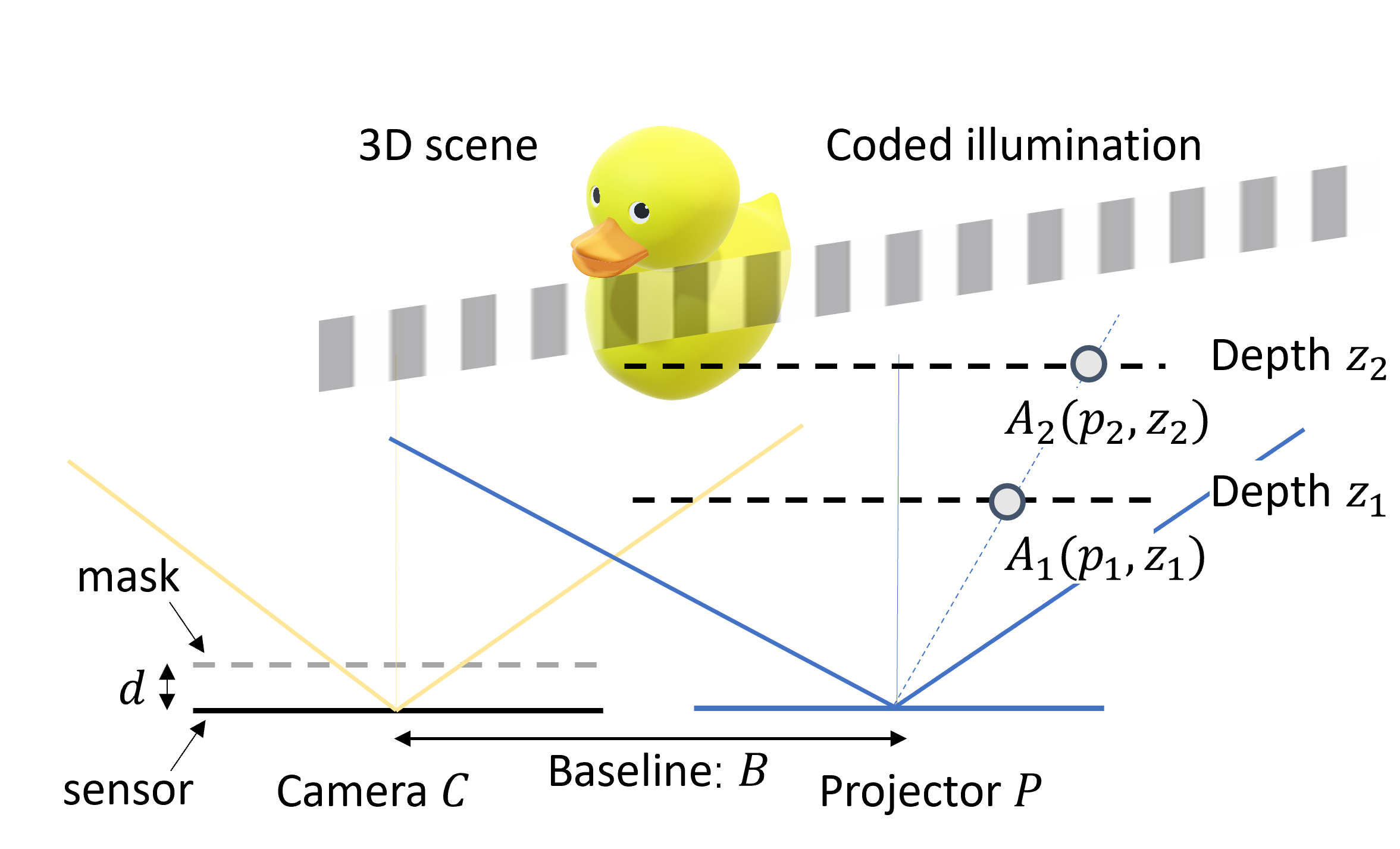
The general system in (1) can be simplified depending on the system design and placement and pattern of the mask. In our proposed method, we use a separable model proposed in [1], where we use a rank-1 matrix as the amplitude mask. With the separable mask placed parallel to the image sensor, the PSF of an arbitrary point, , will be a rank-1 matrix, and the general model in (1) can be written in a simpler form as a separable system.
Suppose we discretize the continuous scene into depth planes , each with pixels. The separable system can be represented in the following compact form:
| (2) |
represents sensor measurements and represents the system matrix for the -th depth plane.
3.2 Coded Illumination
We use a projector separated by baseline distance from the camera to illuminate the scene with a sequence of coded illumination patterns (as illustrated in Figure 1. The effect of coded illumination can be modelled as an element-wise product between the illumination pattern and the scene. We divide the field-of-view (FOV) cone of the projector into angles, which also determines the spatial discretization of the scene. We generate a sequence of illumination patterns and capture the corresponding measurements on the sensor. The measurements captured for -th pattern can be represented as
| (3) |
Note that we assume the same illumination pattern for every depth plane at a time. This is because we use the projector to determine the scene discretization at every depth plane.
To recover the 3D scene as a stack of planes, , we solve the following regularized least-squares problem:
| (4) |
represents a finite difference operator that computes local gradients of the 3D volume along spatial and depth directions. The norm of the local differences provides the 3D total variation function that we use as the regularization function. The total variation function constrains the magnitude of the local variation in the reconstruction and is widely used in ill-conditioned image recovery problems [36, 16]. The optimization problem in (4) can be solved using an iterative least-squares solvers; we used the TVreg package [37].
3.3 Effect of Baseline on Depth-Dependent PSFs
As discussed in previous work on 3D lensless imaging [3, 5, 13, 6], the points at different depth in the scene provide a scaled version of the mask pattern as the sensor response. However, if the object is far from the lensless camera, the depth-dependent differences in the sensor reponse become almost negligible.
Coded illumination in our proposed system provides robust 3D reconstruction for two main reasons: (1) Coded illumination selects a subset of scene points that contribute to each sensor measurement. (2) Spatial separation between camera and projector (i.e., baseline) maps depth variations in scene points into depth-dependent shifts in the sensor response. Since shifted versions of the the mask pattern can be easily resolved compare to the scaled versions, the baseline plays a critical role in quality of 3D reconstruction.
Let us consider the 1D case of our proposed framework, the projector is placed at a baseline distance away from the camera , as shown in Figure 1. For an arbitrary point at in the coordinate system of , its measurements on camera can be written as
| (5) |
where denotes the coordinates on the camera sensor and denotes the sensor-to-mask distance. The coordinates of two arbitrary points and on the same ray of the projector in the coordinate system of become , in the coordinate system of camera (because of the the baseline between camera and projector). We can represent the camera response or PSF corresponding to each of these points as
| (6) |
| (7) |
Note that because the two points are at different depths on the same ray angle. Therefore, the PSF of points and differ from each other with a scaling factor and a depth-dependent shift .
Specifically, when the object is far from the camera, we can often ignore the difference in depth scaling factor , and the difference of the depth-dependent shift becomes When the baseline is zero, two point light sources on the same ray are the scaled versions of each other, and the scaling factor becomes almost the same when the object distance is large. However, by separating the camera and project by baseline distance , the camera observes a shifted 3D grid; two points on the shifted grid provide an angular difference with respect to the camera. Therefore, the depth resolvability of the system improves. This effect was previously discussed in [12] for more general geometries with multiple cameras.
In general, the projector and camera can be separated laterally and axially. Lateral separation provides depth-dependent shifts of the PSF, which we discussed in (6) and (7). Axial separation would provide depth-dependent scaling and shifts of the PSF, which can also be deduced from (6) and (7). For instance, if the camera and projector are separated axially by , the depth-dependent shifts can be calculated by replacing with , respectively. Since these terms appear in the denominator, their influence on the PSF shift will be small compared to lateral baseline .
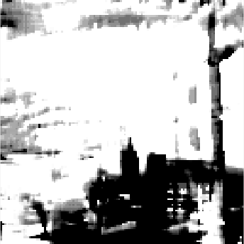
| original image | uniform | 16 lines | 48 lines | |
 |
 |
 |
 |
|
| original depth | SSIM: 0.28 | 0.64 | 0.66 | |
 |
 |
 |
 |
|
| RMSE:8.28cm | 4.53cm | 2.96cm |
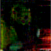
| original image | Baseline: 0cm | 1cm | 5cm | |
|
 |
 |
|
|
| original depth | SSIM: 0.91 | 0.63 | 0.66 | |
|
 |
 |
|
|
| RMSE:8.57cm | 6.60cm | 2.96cm |
4 Simulation Results
To validate the performance of the proposed algorithm, we simulate a lensless imaging system where a coded-mask is placed on top of an image sensor. We use a separable maximum length sequence (MLS) mask pattern [9, 1]. The size of each mask feature is 60m, and the sensor-mask distance is 2mm. The sensor pitch in the simulation is 4.8m and the total number of pixels on the sensors is . We simulate a multi-plane 3D scene with voxels. The simulated sensor noise consists of photon noise and read noise, and the noisy sensor measurements can be described as
| (8) |
where and refers to original and noisy measurements, where stands for the full-well capacity of the sensor, and represents the gain value. The variance and is the dynamic range.
4.1 Effect of Illumination Patterns
We test different types of binary illumination patterns for the simulation. The patterns are designed to be binary to keep the model simple and to avoid the effect of non-linearity caused by the Gamma curve of the projector..
Uniform. One pattern that illuminates all the pixels simultaneously;
Random. A sequence of separable binary random matrices. We ensure that the union of all the patterns should illuminate all the pixels (i.e., if we add up all the illumination patterns, they should not have zero entries anywhere).
Shifting dots array. The base illumination pattern consists of dots separated by pixels along the horizontal and vertical directions. We then generate a total of illumination patterns, each of which is a shifted version of the base pattern. The summation of all the patterns will give us a uniform illumination pattern.
Shifting lines. Similar to shifting dots array, the base illumination patterns consist of horizontal lines separated by pixels along vertical axis and vertical lines separated along horizontal axis. We then generate shifted version of these two base patterns. The summation of all the patterns is a uniform illumination pattern.
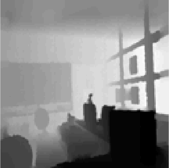
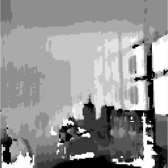
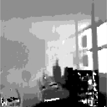
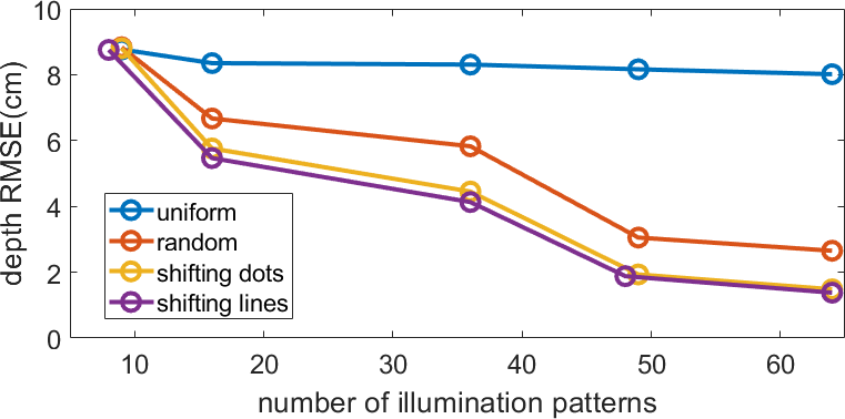
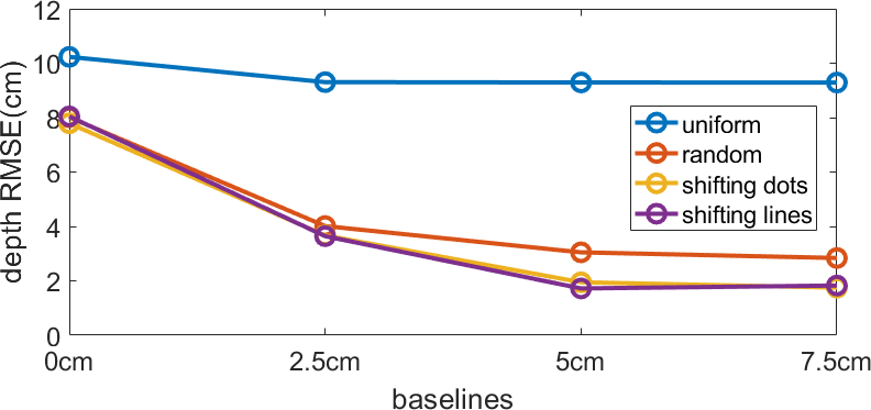
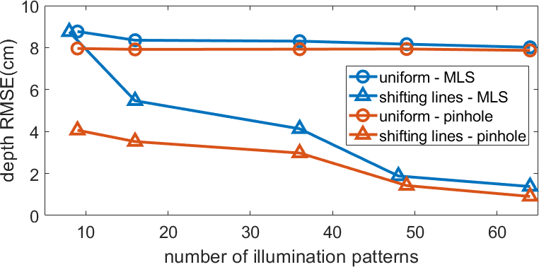
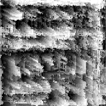
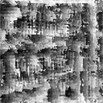
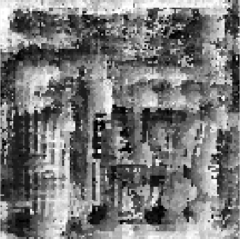
We present simulation results with different number and types of illumination patterns in Figure 2. The simulated test scene is taken from NYU depth dataset[38]. The depth of scene is rescaled into the range from to and discretized into 50 depth planes to simulate the sensor measurements. The camera setup and the baseline between camera and projector are fixed during the simulation. The shifting lines and shifting dots outperform the uniform pattern in terms of depth RMSE. Also, the depth RMSE drops as we increase the number of illumination patterns.
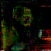
| MLS mask | pinhole | MLS mask | pinhole |
| 16 lines | 16 lines | 48 lines | 48 lines |
|
 |
|
 |
| SSIM: 0.64 | 0.66 | 0.66 | 0.69 |
|
 |
|
 |
| RMSE: 4.53cm | 3.52cm | 2.96cm | 1.72cm |
| 16 coded | 16 mask | 48 coded | 48 mask |
| illuminations | shifts [13] | illuminations | shifts [13] |
|
 |
|
 |
| SSIM: 0.64 | 0.61 | 0.66 | 0.62 |
|
 |
|
 |
| RMSE: 4.53cm | 10.48cm | 2.96cm | 9.87cm |
4.2 Effects of Baseline
The baseline between the lensless camera and the projector affects the depth resolvability of the system. Shifting the lensless camera by a distance, the camera observes the scene from a side view and transfers the depth difference of two points into angular difference. We present simulation results in Figure 3 to demonstrate the effect of camera-projector baselines. The number of illumination patterns for all the simulation are the same. We then fix the baseline along axial direction to 0cm and the baseline along lateral direction as . As shown in Figure 3, the depth RMSE is decreased as we increase the baseline between the camera and the projector. When the baseline is zero, which means the camera and projector are overlapped, we barely distinguish any depth.
One important consideration for our method is that the target object should lie within the intersection of the sensor FOV cone and the projector illumination cone. As we increase the baseline, the intersection of the two cones is pushed farther from the sensor. Therefore, we should determine the maximum baseline based on the object distance, sensor FOV, and projector cone. If we increase the baseline beyond the maximum limit, then the reconstruction quality can decrease.
4.3 Comparison with an Ideal Pinhole Camera
In existing structured illumination methods [27, 30, 31], a lens-based camera is used to capture the scene from the side view of the projector and depth map can be accurately reconstructed by triangulation. We can model the lens-based camera as an ideal pinhole camera (ignoring photon or sensor noise) for the sake of comparison with our method. We present simulation results comparing a pinhole-based camera with structured illumination in Figure 4. The baseline between the projector and the camera is fixed at 5cm in all the simulations. Results in Figure 4 show that the pinhole mask (that represents an ideal lens-based camera) provides better results compared to the MLS mask. Compared to mask-based lensless camera where the sensor measurements are multiplexed, a lens-based system can offer better conditioning and depth reconstruction. Nevertheless, a lens-based camera imposes additional burden in terms of device thickness, weight, and geometry.
4.4 Comparison with Multishot Lensless System
In our proposed method, multiple frames of measurements are captured, which introduce additional limitations such as long capture time and low frame rate. In Figure 5, we present simulation results comparing our method with another multi-shot lensless imaging system called SweepCam [13]. SweepCam captures multiple frames of sensor measurements while translating the mask laterally. The translation of the mask offers a perspective shift in the measurements that depends on the depth of objects in the scene. In our simulations, the SweepCam mask is translated to 48 positions within a range of . However, since the translating distance of the mask is limited by the sensor area, the SweepCam method fails to resolve the depths when the scene is farther than 30cm.
| 58cm | 62cm | 66cm | all-in-focus image | reconstructed depth | original |
|---|---|---|---|---|---|
|
uniform 
|
 |
 |
 |
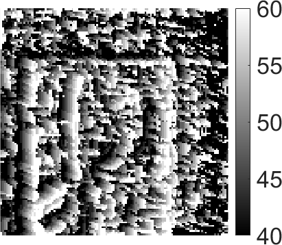 |

image |
|
48 shifting lines 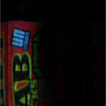
|
 |
 |
 |
 |
depth |
|
uniform 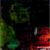
|
 |
 |
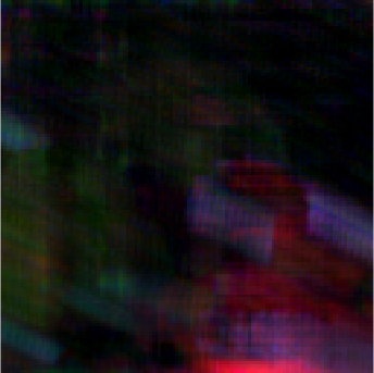 |
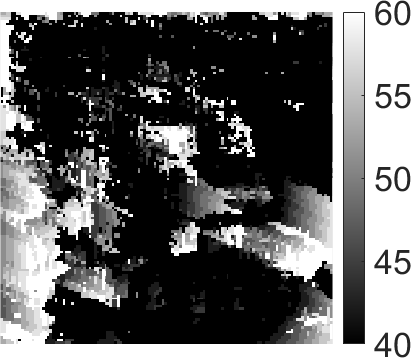 |

image |
|
48 shifting lines 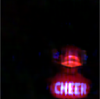
|
 |
 |
 |
 |
depth |
5 Experimental Results
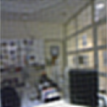
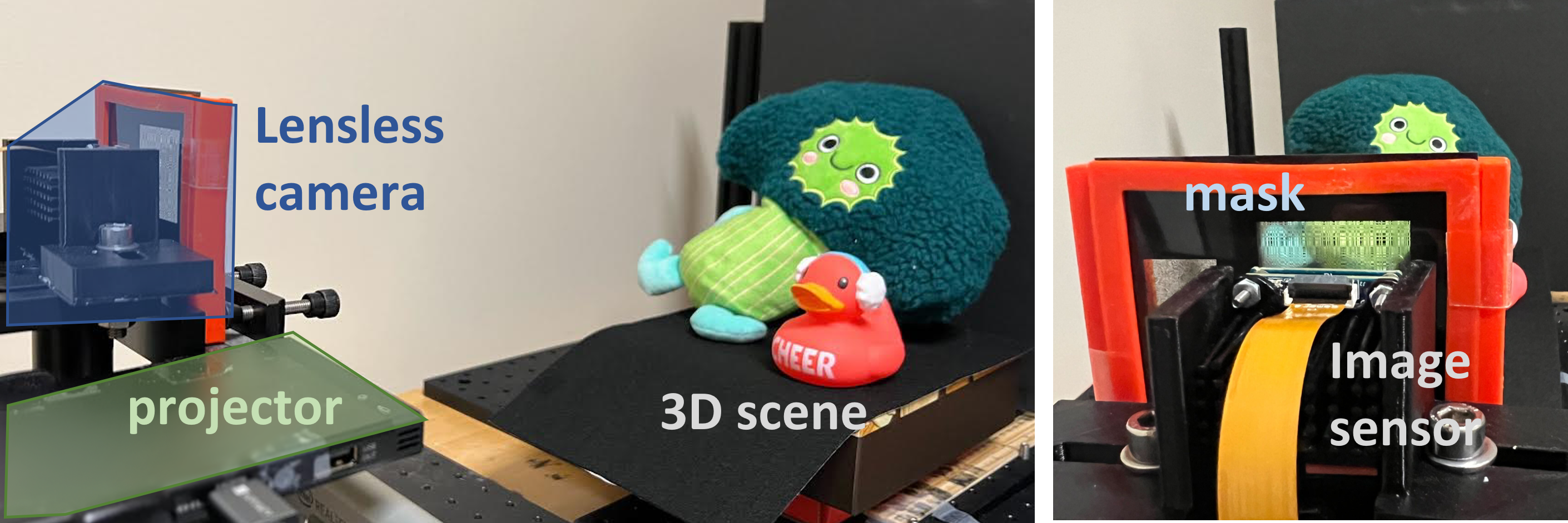
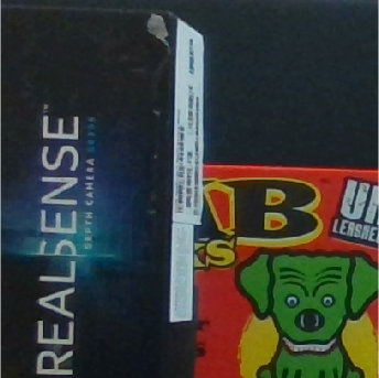
To validate our proposed method, we built a prototype with a lensless camera and a Sony MP-CL1 laser projector, shown in Figure 6. The lensless camera prototype consists of an image sensor and a coded amplitude mask on top of it. We employ the outer-product of two MLS vectors as our mask pattern. The mask has square features. The pixel pitch is 60m and the sensor-to-mask distance is 2mm. We use a Sony IMX183 sensor and bin sensor pixels, which yields the effective sensor pitch close to 4.8m. We record measurements from the sensor and the effective sensor size is . We place the test 3D objects within 40cm and 60cm depth range with respect to the camera. Finally, we reconstruct voxels in the illuminated area. In our method, the lensless camera and the projector are separated by a 55mm baseline. We first reconstruct the depth planes by solving the regularized least-squares problem in (4). Then we create an all-in-focus image and depth map by selecting the pixel with the maximum amplitude along each light ray.
In our experiments, the pixel grid of the scene, illumination patterns , the system matrices at each depth must be correctly aligned; otherwise, we will get artifacts in the reconstruction. To avoid any grid mismatch, we use the same projector to calibrate the system matrices and generate the illumination patterns in our experiments.
| original | uniform | 16 shifting dots | 49 shifting dots | 16 shifting lines | 48 shifting lines | |
|---|---|---|---|---|---|---|
|
image |
 |
 |
 |
 |
 |
 |
|
depth |
 |
 |
 |
 |
 |
 |
|
image |
 |
 |
 |
 |
 |
 |
|
depth |
 |
 |
 |
 |
 |
 |
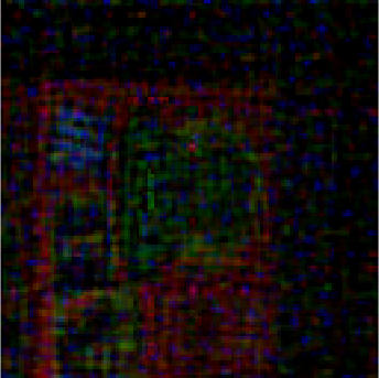
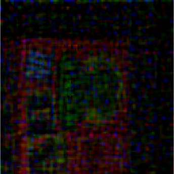
5.1 Effect of Illumination Patterns
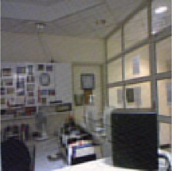
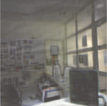
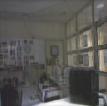
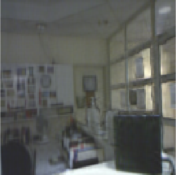
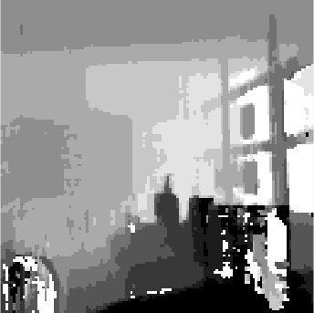
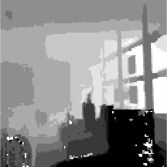
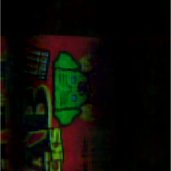
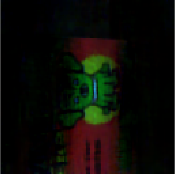
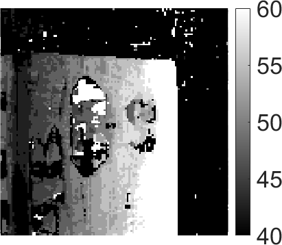
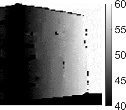
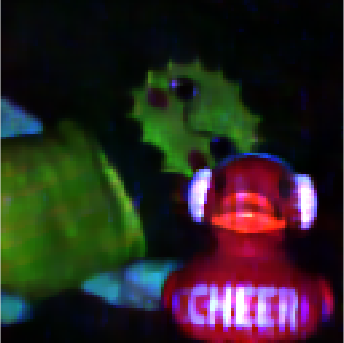
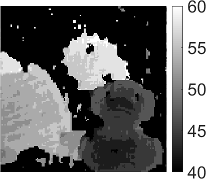
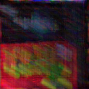
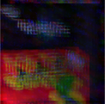
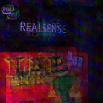
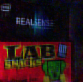
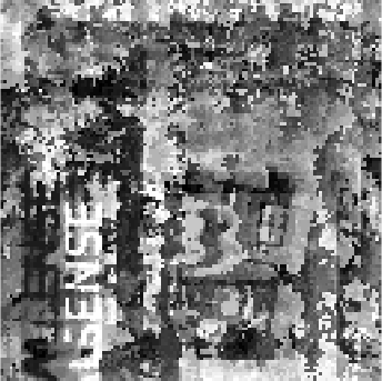
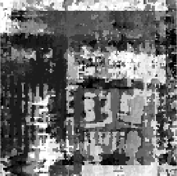
We present experimental results of 3D reconstruction with our proposed method for real objects in Figures 7 and 9. We show the results of reconstructed depth planes, estimated all-in-focus images and depth maps using uniform, shifting lines, and shifting dots patterns. For comparison, we captured the original image and depth map for each scene using Intel RealSense D415 depth camera, where the baseline between the lens-based camera and the projector is 55mm.
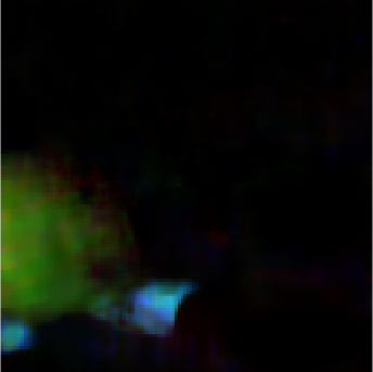
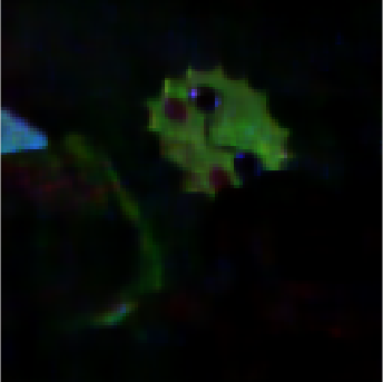
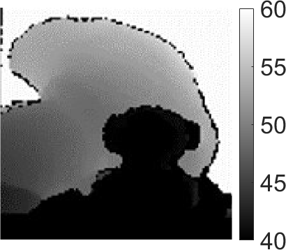
The results in Figure 7 compare 3D reconstruction with uniform and 48 shifting lines. In the first two rows, the scene is a slanted box, containing continuous depth varying from 40cm to 60cm. In the last two rows, the scene contains a red toy located at 40cm and a green toy lying from 50cm to 60cm. The results in the first three columns in Figure 7 represent three depth planes at 58cm, 62cm, and 66cm. The results show that the correct depth can be easily distinguished in images reconstructed with 48 shifting lines pattern, whereas depth planes reconstructed with the uniform illumination pattern show incorrect depth and intensity. The estimated all-in-focus image and depth maps for 48 shifting lines also appear significantly better than those from the uniform illumination patterns.
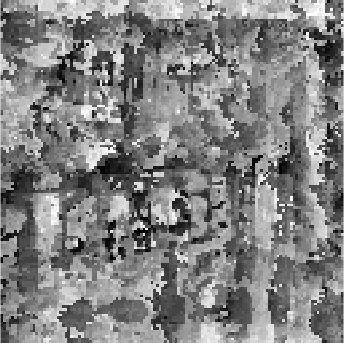
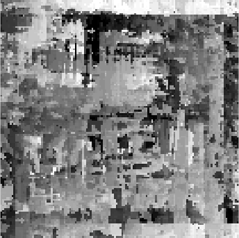
The results in Figure 8 compare different number and types of illumination patterns. We observe that the uniform illumination pattern barely recover any depth. The illumination pattern with 16 and 49 shifting dots provide better results than uniform illumination. 16 shifting lines provide slightly better results compared to shifting dots and 48 shifting lines provide significanlty better image and depth map.
In summary, the ill-conditioned system matrices with uniform illumination pattern cause various artifacts in 3D reconstruction. Capturing measurements from coded illumination improves the conditioning of the overall system and the reconstructed images have better spatial and depth resolution. Increasing the number of illumination patterns provides better reconstruction. More illumination patterns would require longer acquisition time as well, which enforces a trade off between the quality of reconstruction and data acquisition time.
| 51cm | 55cm | 59cm |
|---|---|---|
|
5.5cm baseline 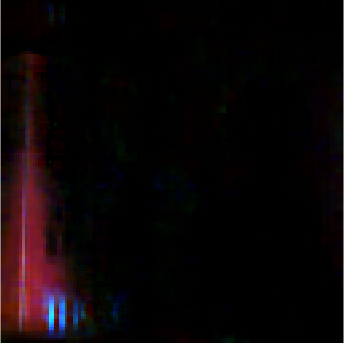
|
 |
 |
|
10.5cm baseline 
|
 |
 |
5.2 Effect of Baselines
We show experimental results for different baselines in Figure 9. We captured the same scene with and baseline and performed 3D reconstruction with the respective measurements. The results in Figure 9 show that 10.5cm baseline offers finer depth resolution (indicated as narrow depth of field) compared to the reconstruction with 5.5cm baseline. The improvement is small, and this effect was observed in the simulation results in Figure 3(b) that show the depth RMSE of the system tapers off as we increase the baseline between the camera and the projector.
6 Conclusion and Discussion
We propose a framework for combining coded illumination with lensless imaging for 3D lensless imaging. We present simulation and real experiment results to demonstrate that our proposed method can achieve significantly improved 3D reconstruction with multiple coded illumination compared to uniform illumination. Such a mask-based lensless camera can be useful in space-limited applications such as under-the-display or large-area sensing, where installing a lens-based camera can be challenging. Our proposed setup can also be useful for distributed lensless sensors (in different shapes and geometries), where we may want to image over a large area, large field-of-view, but keep the devices flat, thin, and lens-free.
Limitaitons. Our current setup can add extra cost and complexity to the system design because of the illumination source. The need to capture multiple shots can also increase the data acquisition time and restrict the usage for static or slow-moving objects.
Future directions. Extending our method to dynamic scenes is a natural direction for future work. We also need to further explore if some other illumination patters can offer better 3D reconstruction for scenes with different depth profiles. Co-design of illumination patterns, mask pattern/placement, and overall system arrangement can further improve the quality of 3D reconstruction. On the algorithmic side, the recovery algorithm can be improved by including more sophisticated priors for the 3D scenes.
References
- [1] M. S. Asif, A. Ayremlou, A. Sankaranarayanan, A. Veeraraghavan, and R. G. Baraniuk, “Flatcam: Thin, lensless cameras using coded aperture and computation,” IEEE Transactions on Computational Imaging, vol. 3, no. 3, pp. 384–397, 2017.
- [2] V. Boominathan, J. K. Adams, M. S. Asif, B. W. Avants, J. T. Robinson, R. G. Baraniuk, A. C. Sankaranarayanan, and A. Veeraraghavan, “Lensless imaging: A computational renaissance,” IEEE Signal Processing Magazine, vol. 33, no. 5, pp. 23–35, 2016.
- [3] N. Antipa, G. Kuo, R. Heckel, B. Mildenhall, E. Bostan, R. Ng, and L. Waller, “Diffusercam: lensless single-exposure 3d imaging,” Optica, vol. 5, no. 1, pp. 1–9, Jan 2018.
- [4] V. Boominathan, J. T. Robinson, L. Waller, and A. Veeraraghavan, “Recent advances in lensless imaging,” Optica, vol. 9, no. 1, pp. 1–16, 2022.
- [5] J. K. Adams, V. Boominathan, B. W. Avants, D. G. Vercosa, F. Ye, R. G. Baraniuk, J. T. Robinson, and A. Veeraraghavan, “Single-frame 3d fluorescence microscopy with ultraminiature lensless flatscope,” Science Advances, vol. 3, no. 12, 2017.
- [6] Y. Zheng and M. Salman Asif, “Joint image and depth estimation with mask-based lensless cameras,” IEEE Transactions on Computational Imaging, vol. 6, pp. 1167–1178, 2020.
- [7] A. Yedidia, C. Thrampoulidis, and G. Wornell, “Analysis and optimization of aperture design in computational imaging,” IEEE International Conference on Acoustics, Speech, and Signal Processing, pp. 4029–4033, April 2018.
- [8] E. E. Fenimore and T. M. Cannon, “Coded aperture imaging with uniformly redundant arrays,” Appl. Opt., vol. 17, no. 3, pp. 337–347, Feb 1978.
- [9] A. Busboom, H. Elders-Boll, and H. D. Schotten, “Uniformly redundant arrays,” Experimental Astronomy, vol. 8, no. 2, pp. 97–123, Jun 1998.
- [10] T. M. Cannon and E. E. Fenimore, “Coded Aperture Imaging: Many Holes Make Light Work,” Optical Engineering, vol. 19, p. 283, Jun. 1980.
- [11] A. Levin, R. Fergus, F. Durand, and W. T. Freeman, “Image and depth from a conventional camera with a coded aperture,” ACM Trans. Graph., vol. 26, no. 3, Jul. 2007.
- [12] M. S. Asif, “Lensless 3d imaging using mask-based cameras,” in 2018 IEEE International Conference on Acoustics, Speech and Signal Processing (ICASSP). IEEE, 2018, pp. 6498–6502.
- [13] Y. Hua, S. Nakamura, M. S. Asif, and A. C. Sankaranarayanan, “Sweepcam — depth-aware lensless imaging using programmable masks,” IEEE Transactions on Pattern Analysis and Machine Intelligence, vol. 42, no. 7, pp. 1606–1617, 2020.
- [14] Y. Zheng, Y. Hua, A. C. Sankaranarayanan, and M. S. Asif, “A simple framework for 3d lensless imaging with programmable masks,” in Proceedings of the IEEE/CVF International Conference on Computer Vision, 2021, pp. 2603–2612.
- [15] E. J. Candès, J. K. Romberg, and T. Tao, “Stable signal recovery from incomplete and inaccurate measurements,” Communications on Pure and Applied Mathematics, vol. 59, no. 8, pp. 1207–1223, 2006.
- [16] L. I. Rudin, S. Osher, and E. Fatemi, “Nonlinear total variation based noise removal algorithms,” Phys. D, vol. 60, no. 1-4, pp. 259–268, Nov. 1992.
- [17] D. L. Donoho, “Compressed sensing,” IEEE Transactions on Information Theory, vol. 52, no. 4, pp. 1289–1306, April 2006.
- [18] R. G. Baraniuk, “Compressive sensing [lecture notes],” IEEE Signal Processing Magazine, vol. 24, no. 4, pp. 118–121, 2007.
- [19] B. Recht, M. Fazel, and P. A. Parrilo, “Guaranteed minimum-rank solutions of linear matrix equations via nuclear norm minimization,” SIAM Review, vol. 52, no. 3, pp. 471–501, 2010.
- [20] R. Hyder, V. Shah, C. Hegde, and M. S. Asif, “Alternating phase projected gradient descent with generative priors for solving compressive phase retrieval,” in IEEE International Conference on Acoustics, Speech and Signal Processing (ICASSP), 2019, pp. 7705–7709.
- [21] A. Bora, A. Jalal, E. Price, and A. G. Dimakis, “Compressed sensing using generative models,” in Proceedings of the 34th International Conference on Machine Learning - Volume 70, ser. ICML’17. JMLR.org, 2017, pp. 537–546.
- [22] P. Hand, O. Leong, and V. Voroninski, “Phase retrieval under a generative prior,” in Advances in Neural Information Processing Systems 31, S. Bengio, H. Wallach, H. Larochelle, K. Grauman, N. Cesa-Bianchi, and R. Garnett, Eds. Curran Associates, Inc., 2018, pp. 9136–9146.
- [23] S. Khan, V. Sundar, V. Boominathan, A. Veeraraghavan, and K. Mitra, “Flatnet: Towards photorealistic scene reconstruction from lensless measurements,” IEEE Transactions on Pattern Analysis and Machine Intelligence, oct 2020.
- [24] V. Boominathan, J. K. Adams, J. T. Robinson, and A. Veeraraghavan, “Phlatcam: Designed phase-mask based thin lensless camera,” IEEE Transactions on Pattern Analysis and Machine Intelligence, vol. 42, no. 7, pp. 1618–1629, 2020.
- [25] K. Monakhova, J. Yurtsever, G. Kuo, N. Antipa, K. Yanny, and L. Waller, “Learned reconstructions for practical mask-based lensless imaging,” Opt. Express, vol. 27, no. 20, pp. 28 075–28 090, Sep 2019.
- [26] K. Monakhova, V. Tran, G. Kuo, and L. Waller, “Untrained networks for compressive lensless photography,” Opt. Express, vol. 29, no. 13, pp. 20 913–20 929, Jun 2021.
- [27] M. G. L. Gustafsson, L. Shao, P. M. Carlton, C. J. R. Wang, I. N. Golubovskaya, W. Z. Cande, D. A. Agard, and J. W. Sedat, “Three-Dimensional Resolution Doubling in Wide-Field Fluorescence Microscopy by Structured Illumination,” Biophysical Journal, vol. 94, pp. 4957–4970, Jun. 2008.
- [28] S. K. Nayar and M. Gupta, “Diffuse structured light,” in 2012 IEEE International Conference on Computational Photography (ICCP), April 2012, pp. 1–11.
- [29] D. Fofi, T. Sliwa, and Y. Voisin, “A comparative survey on invisible structured light,” in IST/SPIE Electronic Imaging, 2004.
- [30] R. Heintzmann and C. G. Cremer, “Laterally modulated excitation microscopy: improvement of resolution by using a diffraction grating,” in Optical Biopsies and Microscopic Techniques III, I. J. Bigio, H. Schneckenburger, J. Slavik, K. S. M.D., and P. M. Viallet, Eds., vol. 3568, International Society for Optics and Photonics. SPIE, 1999, pp. 185 – 196.
- [31] M. G. L. Gustafsson, “Surpassing the lateral resolution limit by a factor of two using structured illumination microscopy.” Journal of microscopy, vol. 198 Pt 2, pp. 82–7, 2000.
- [32] Y. Zheng, R. Zhang, and M. S. Asif, “Coded illumination and multiplexing for lensless imaging,” in IEEE International Conference on Acoustics, Speech and Signal Processing (ICASSP). IEEE, 2020, pp. 9250–9253.
- [33] Y. Zheng and M. S. Asif, “Coded illumination for improved lensless imaging,” arXiv preprint arXiv:2111.12862, 2021.
- [34] C. B. S. Burak Gokturk, Hakan Yalcin, “A time-of-flight depth sensor - system description, issues and solutions,” in Conference on Computer Vision and Pattern Recognition Workshop, June 2004, pp. 35–35.
- [35] F. Heide, M. B. Hullin, J. Gregson, and W. Heidrich, “Low-budget transient imaging using photonic mixer devices,” ACM Transactions on Graphics (ToG), vol. 32, no. 4, p. 45, 2013.
- [36] C. Li, W. Yin, H. Jiang, and Y. Zhang, “An efficient augmented lagrangian method with applications to total variation minimization,” Computational Optimization and Applications, vol. 56, no. 3, pp. 507–530, 2013.
- [37] T. L. Jensen, J. H. Jørgensen, P. C. Hansen, and S. H. Jensen, “Implementation of an optimal first-order method for strongly convex total variation regularization,” in BIT Numerical Mathematics, vol. 52, no. 2, 2012, pp. 329–356.
- [38] P. K. Nathan Silberman, Derek Hoiem and R. Fergus, “Indoor segmentation and support inference from rgbd images,” in ECCV, 2012.
[![[Uncaptioned image]](https://cdn.awesomepapers.org/papers/1115470b-f44a-4431-a5fe-913c73a4d111/yucheng.jpg) ]
YUCHENG ZHENG received the B.Sc. degree in electrical engineering from the Nanjing University of Aeronautics and Astronautics, Nanjing, China in 2017. He is currently working toward the Ph.D. degree at the University of California, Riverside, CA, USA. His current research interests include computational imaging, computer vision and signal processing.
]
YUCHENG ZHENG received the B.Sc. degree in electrical engineering from the Nanjing University of Aeronautics and Astronautics, Nanjing, China in 2017. He is currently working toward the Ph.D. degree at the University of California, Riverside, CA, USA. His current research interests include computational imaging, computer vision and signal processing.
[![[Uncaptioned image]](https://cdn.awesomepapers.org/papers/1115470b-f44a-4431-a5fe-913c73a4d111/salman.jpg) ]
M. SALMAN ASIF (Senior Member, IEEE) received his B.Sc. degree from the University of Engineering and Technology, Lahore, Pakistan, and his M.S and Ph.D. degrees from the Georgia Institute of Technology, Atlanta, Georgia, USA. He is currently an Associate Professor at the University of California Riverside, USA. Prior to that he worked as a Postdoctoral Researcher at Rice University and a Senior Research Engineer at Samsung Research America, Dallas. He has received NSF CAREER Award, Google Faculty Award, Hershel M. Rich Outstanding Invention Award, and UC Regents Faculty Fellowship and Development Awards. His research interests include computational imaging, signal/image processing, computer vision, and machine learning.
]
M. SALMAN ASIF (Senior Member, IEEE) received his B.Sc. degree from the University of Engineering and Technology, Lahore, Pakistan, and his M.S and Ph.D. degrees from the Georgia Institute of Technology, Atlanta, Georgia, USA. He is currently an Associate Professor at the University of California Riverside, USA. Prior to that he worked as a Postdoctoral Researcher at Rice University and a Senior Research Engineer at Samsung Research America, Dallas. He has received NSF CAREER Award, Google Faculty Award, Hershel M. Rich Outstanding Invention Award, and UC Regents Faculty Fellowship and Development Awards. His research interests include computational imaging, signal/image processing, computer vision, and machine learning.