Coincidences with the Artificial Axon
Abstract
The artificial axon is an excitable node built with the basic biomolecular components and supporting action potentials. Here we demonstrate coincidence firing (the AND operation) and other basic electrophysiology features such as increasing firing rates for increasing input currents. We construct the basic unit for a network by connecting two such excitable nodes through an electronic synapse, producing pre/post synaptic behavior in which one axon induces firing in another. We show that the system is well described by the Hodgkin-Huxley model of nerve excitability, and conclude with a brief outlook for realizing large networks of such low voltage “ionics”.
Introduction. Electrical signal conditioning under water is the hallmark of nerve cells. Action potentials - electrical spikes in the neuron - result from two coupled nonlinear relaxation phenomena, involving “molecular transistors” (voltage gated ion channels in the cell membrane) and supported by the non-equilibrium state created by ionic gradients maintained across the cell membrane. The fundamental mechanism of action potentials was elucidated by Hodgkin and Huxley in the 1950s, and the knowledge constructed since then through electrophysiology experiments on live neurons is monumental Koch (1999); Hille .
And yet, action potentials were never taken out of the live cell into an in vitro setting. This most
interesting of dynamical systems has remained confined to the living world. We recently produced
a similar excitable medium using the biological components in an artificial setting Ariyaratne and Zocchi (2016).
The difficulty of constructiong a functional membrane with two different, correctly oriented ion channel
species was circumvented by the use of what we call the current limited voltage clamp (CLVC) and only
one channel species. The system exhibits threshold behavior and signal amplification, the two hallmarks
of action potentials. Here we use the CLVC to more specifically render the effect of a second ionic species
and channel type, moving our artificial electrophysiology platform closer to a bona fide artificial axon.
We inject currents using a current clamp in the traditional electrophysiology way and demonstrate
multiple firing. We demonstrate coincidence detection: the AND operation, fundamental
for biological neural networks Feinerman et al. (2008). Finally, we connect two axons with an electronic
“synapse” and demonstrate signal propagation and conditioning. We show that the dynamics of the
system is captured by the classic Hodgkin - Huxley (HH) model. We conclude
with the outlook for an extended network of artificial axons.
Reconstituted lipid membranes with and without channels have a history dating from the 1960s
Mueller et al. (1962); one important use today is to study ion channel dynamics Schmidt et al. (2009); Aimon et al. (2011); Ariyaratne and Zocchi (2013); Ruta et al. (2003). The alternative method is patch clamping of real cells
Sakmann and Neher (1984), which has also been used to study the dynamical system of a collection of channels
Salman et al. (1996); Salman and Braun (1997).
Results. In the real axon, two steady state, opposing gradients of and ions, maintained
across the cell membrane by ATP driven molecular pumps, and small but essential leak conductances
for both ions, result in a steady state potential difference across the membrane (the “resting potential”
) which is neither the equilibrium (Nernst) potential for the sodium ions
()
nor the Nernst potential for the potassium ions (). Action potentials are
generated when synapses effectively inject a small current into the neuron, raising the intracellular
potential (we refer potentials to the grounded “outside” of the cell). The voltage sensitive sodium
channels open, forcing . At these positive voltages the potassium channels
open, while the sodium channels close (inactivate), pushing . Finally, the
potassium channels close again, and . The width of the spike (a few ms for
mammalian neurons Koch (1999)) is governed by the interplay of several characteristic time scales;
the amplitude is fixed by the ionic gradients (essentially ).
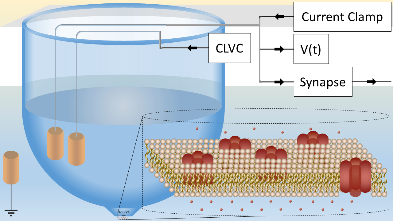
The artificial axon Ariyaratne and Zocchi (2016) is a similarly excitable supported phospholipid bilayer patch
of size , separating two fluid compartments (Fig. 1). This artificial membrane is
studded with oriented voltage gated potassium channels (KvAP), and a concentration
difference , is maintained between
the inside and outside compartments, corresponding to an equilibrium (Nernst) potential:
| (1) |
We keep the system out of equilibrium, at the “resting potential” where
the KvAP channels are closed, using a voltage clamp (Fig. 1), which thus has the role of the second
ionic gradient in a real axon. However, no dynamics can be generated if the voltage is really clamped,
so we limit the current that can be sourced by the clamp using a resistance in series with
the clamp electrode. is chosen so that the maximum current sourced by this “current limited
voltage clamp” (CLVC) is larger than the leak current with channels closed, but smaller than the
channel current with channels open. Then the system can still “fire”. More details on the electronics
and construction of the excitable membrane are found in Ariyaratne and Zocchi (2016) and will be given in
a longer publication in preparation.
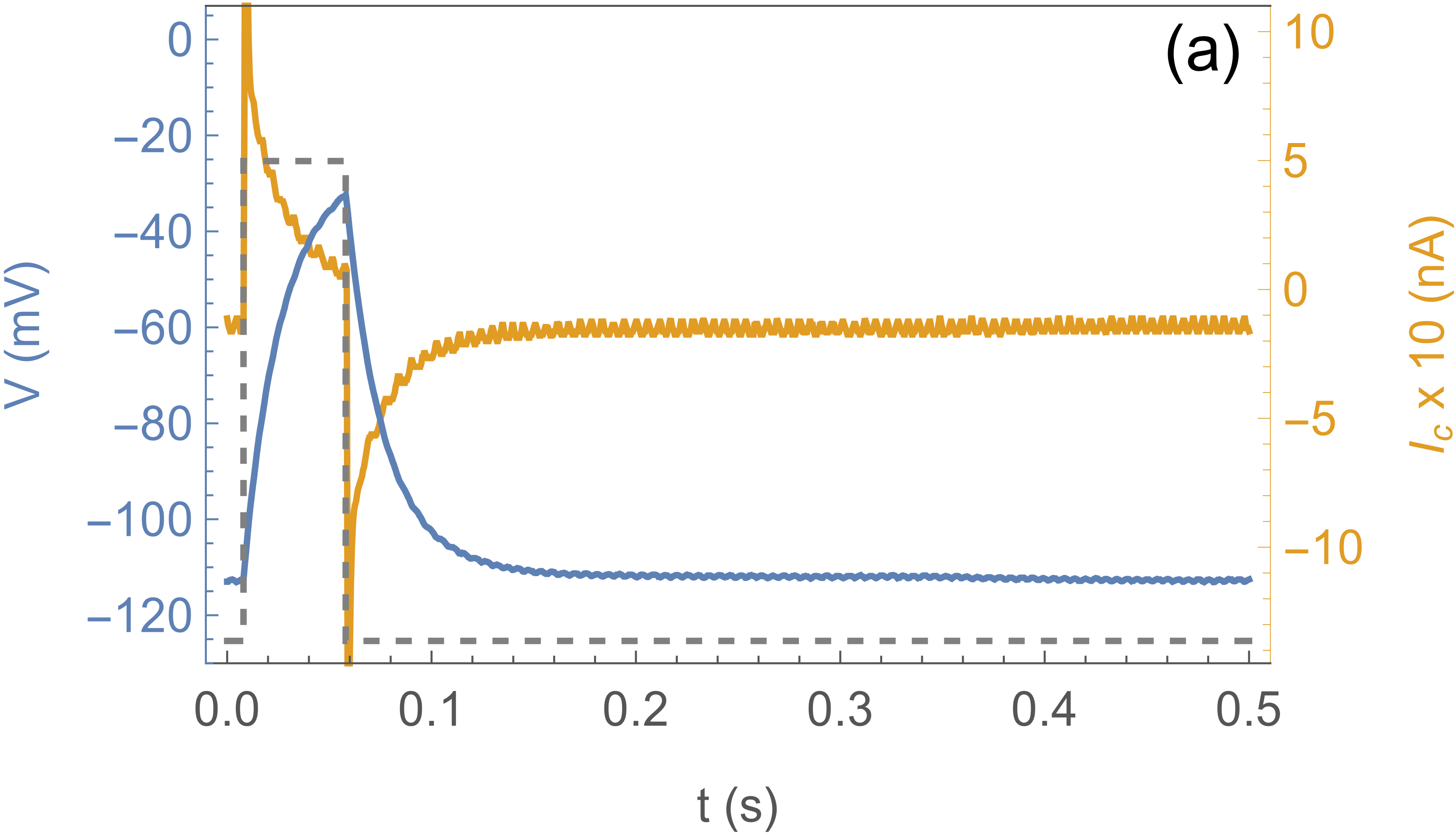
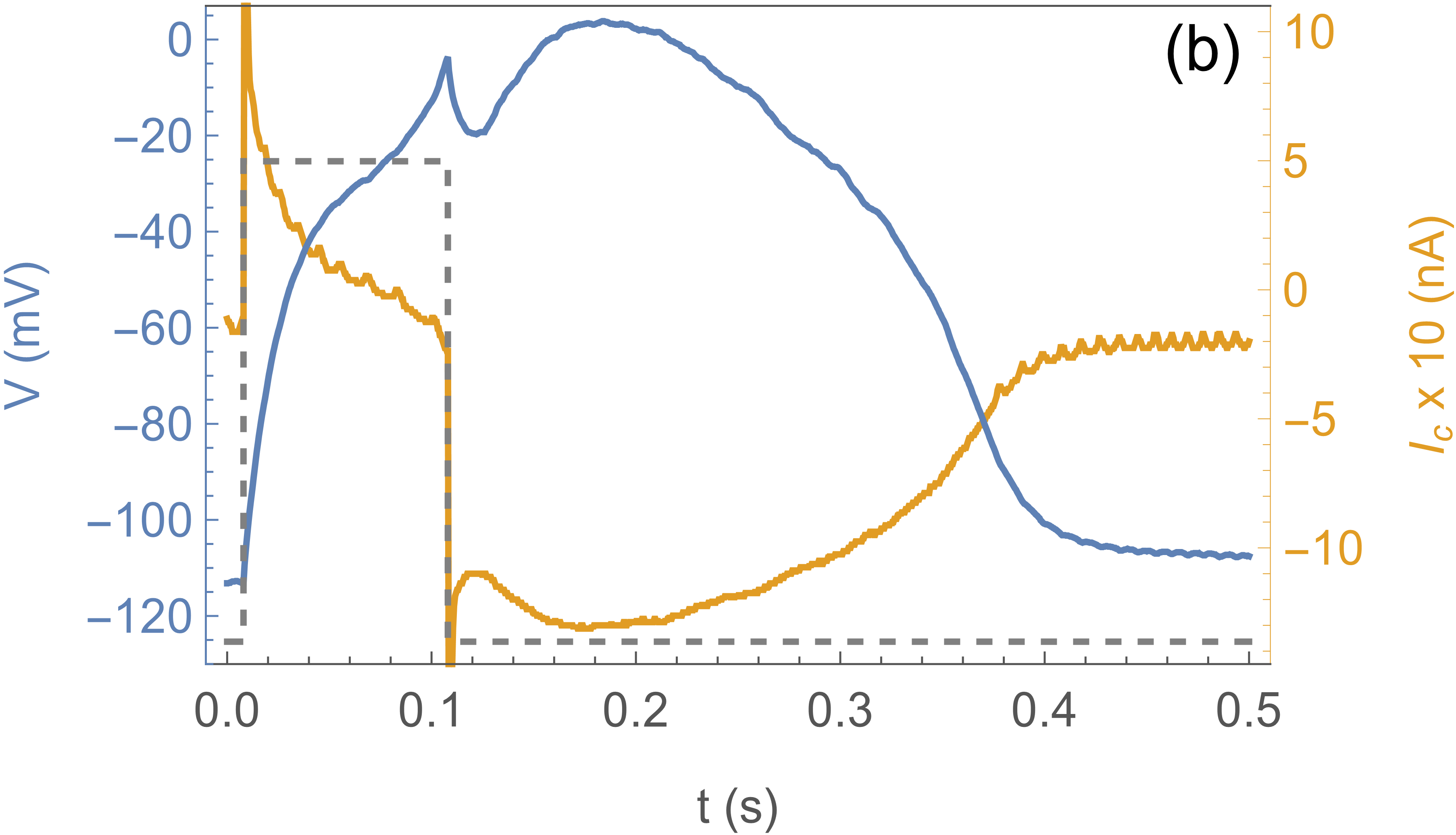
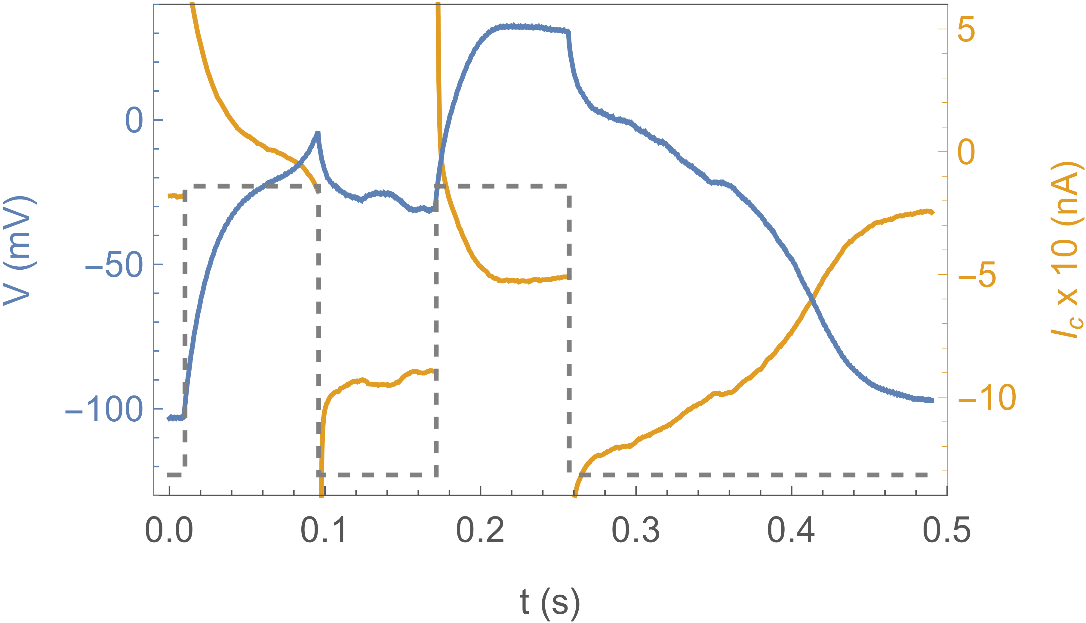
Fig. 2 shows the response of the system to a sub-threshold stimulus (a) and a stimulus above
threshold (b). The blue curve is the actual voltage of the axon, the yellow curve the current
through the clamp, and the dotted curve shows the clamp protocol , which
is a square pulse to . In (a) the effect is simply the charging and discharging of the
membrane capacitance, with an timescale given by the membrane capacitance
and the CLVC resistance . In (b) the square pulse stimulus is longer
( instead of ), and the response is completely different: the system “fires”.
Notice that after the clamp is pulled back down to (at )
the axon voltage continues to climb, because channels are open and the channel current
overwhelms the clamp current. does not quite reach the Nernst potential
because of this competition. The subsequent decrease of is due
to channel inactivation. These traces are essentially deterministic and can be repeated many times.
Two sub-threshold pulses in close proximity will cause the system to fire, implementing an AND operation
or coincidence detector. An example is shown in Fig. 3 where each long pulse alone
is sub-threshold, but two such pulses apart cause firing.
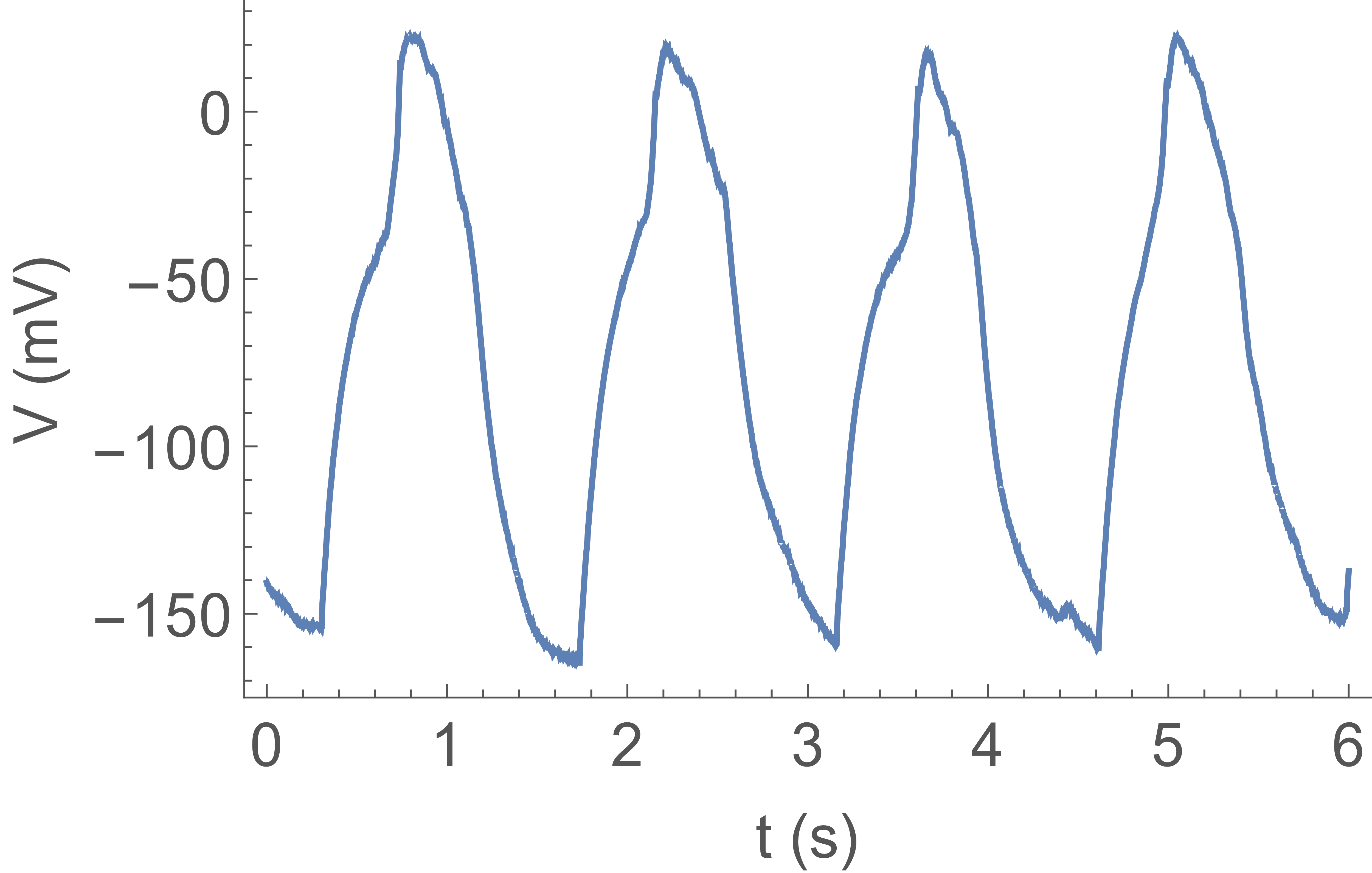
We now proceed to build more features into the system. In electrophysiology, action potentials
are usually evoked using a current clamp to inject the stimulus Hille . This is an electronic analogue
for the synaptic input. Fig. 4 shows a spike train similarly obtained stimulating the artificial
axon with a current clamp, injecting a constant current . However, due to the inactivation
properties of the KvAP, to obtain this dynamics
we must add a “trigger” function to the CLVC, which has the role of the missing second ionic species
and channels. Namely, when the axon voltage exceeds a fixed trigger voltage the CLVC switches from its fixed potential to a more negative potential , for a fixed time , then goes back to .
This is necessary in order that the KvAP channels recover from inactivation.
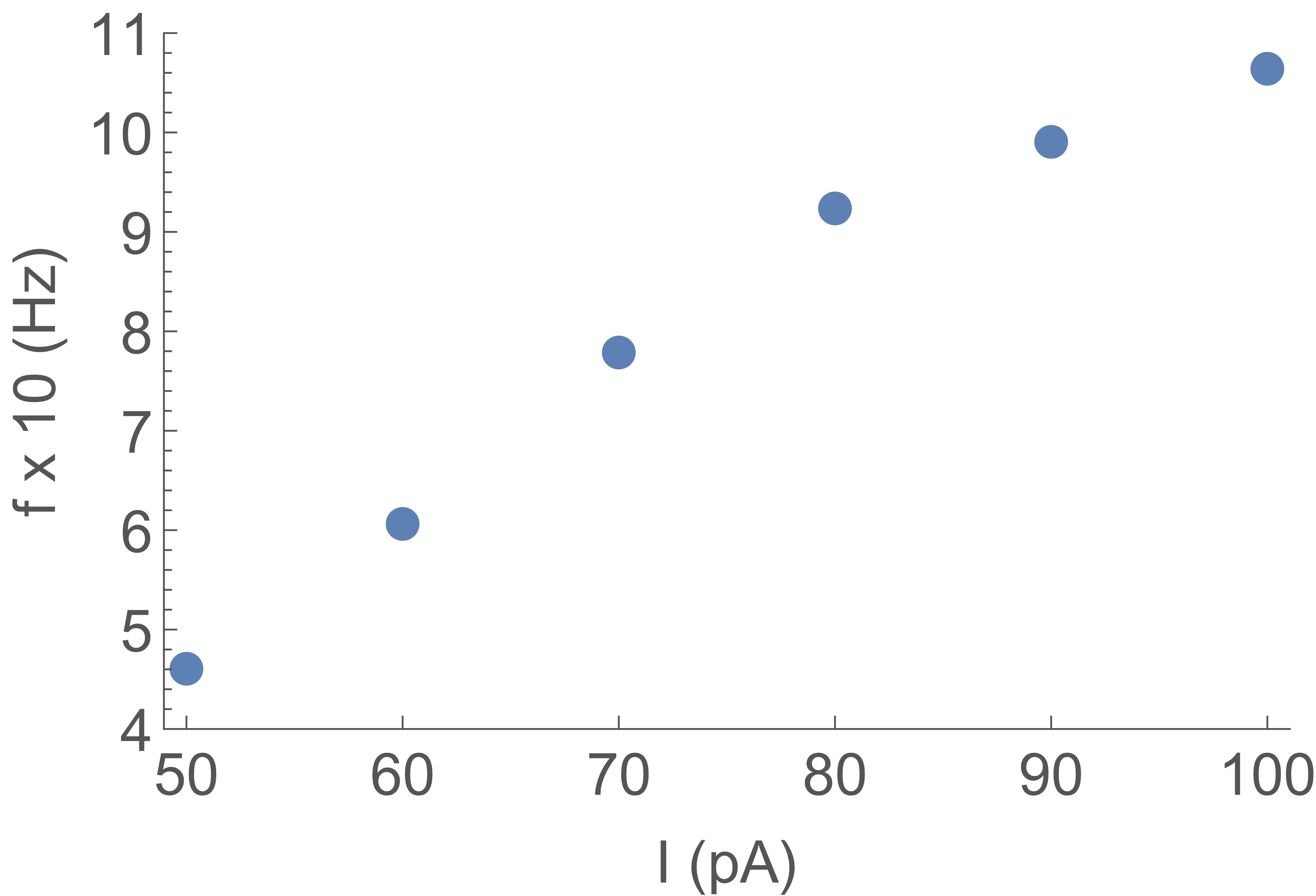
The firing rate is a function of the
input current: Fig. 5 shows the firing rate measured on spike trains as in Fig. 4, for increasing input current.
All other parameters (, , and ) are fixed. The firing rate first increases linearly
with input current, but will eventually saturate due to the constant width of the falling edge of the “action potential”. This behavior is analogous to firing rate observations in patch clamp experiments of real neurons with constant current clamp inputs.
Next we connect two artificial axons through an electronic “synapse” which is a current clamp
injecting into axon 2 a current controlled by the voltage in axon 1. It is a simple analogue
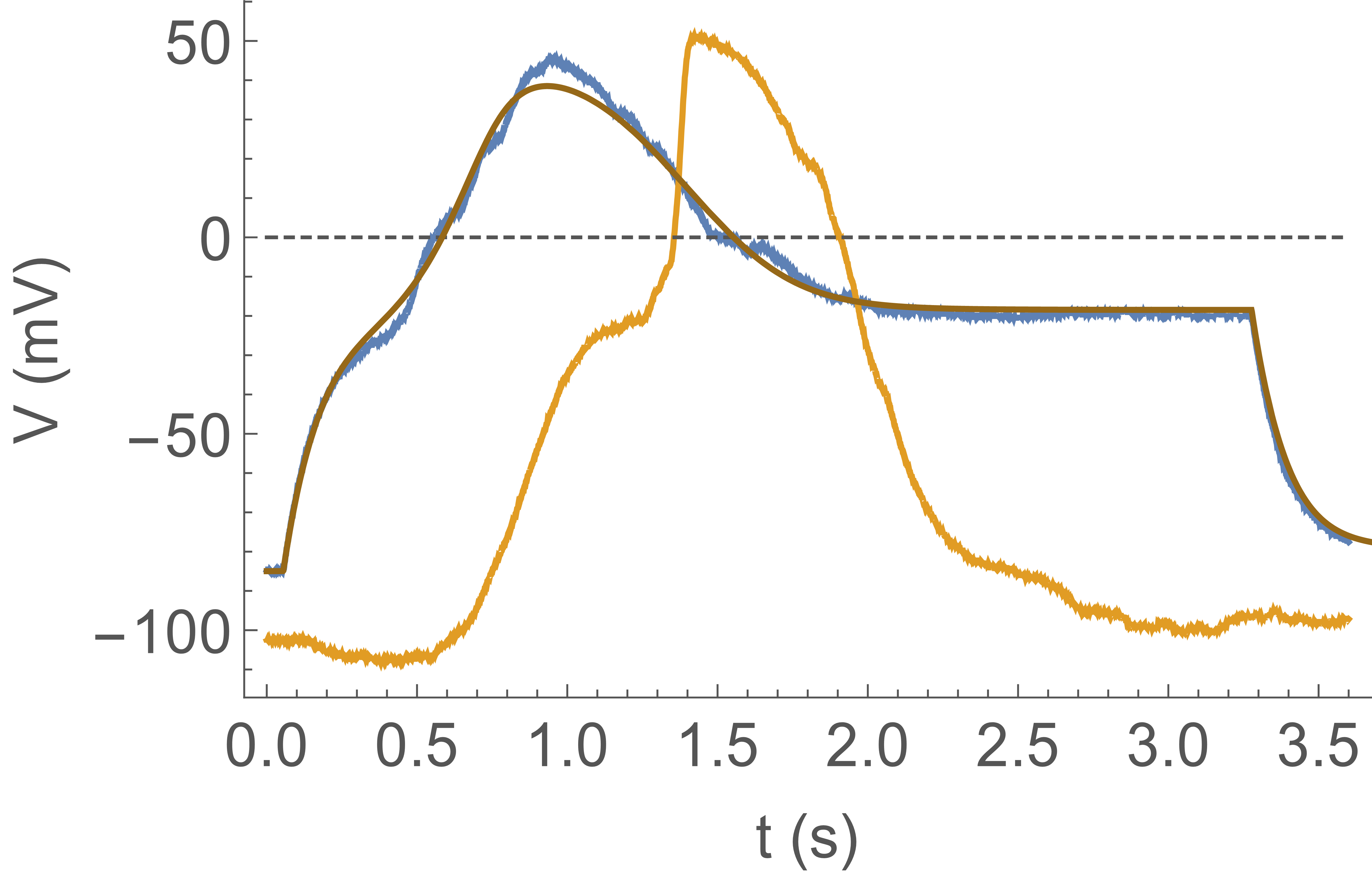
circuit consisting of 220 op-amps and 640 resistors. In Fig. 6 we show action potential propagation from axon 1
(blue trace), through the synapse, to axon 2 (yellow trace). Axon 1 is excited by a current clamp injecting a constant current
for . The hardwired synapse takes as input the voltage of axon 1, ,
and injects into axon 2 a current proportional to the input when :
with and the step function.
There are no triggers in this experiment.
We see that as crosses zero (at ), starts to rise as the synapse injects current.
Axon 2 “fires” (channels open) at . At crosses zero on its way
down; even though the synapse stops injecting current, remains high because the channel current
overwhelms the CLVC current. Eventually channels inactivate and the CLVC pulls the membrane potential
back down to the resting potential. In short, Fig. 6 demonstrates signal propagation between two axons connected
by a synapse: the basic unit for a network.
Model. The dynamics of the artificial axon is captured by the classic
HH model of action potentials (as well as by simplified versions, discussed in a forthcoming publication).
There are three contributions to the current in the system: the ion channel
current where is the number of channels, the open
channel conductance, the probability that channels are open, the Nernst potential, and
the actual axon potential; the leak current ,
being the leak conductance; the clamp current where is
the resistance limiting the current in the CLVC. These currents charge the membrane capacitance :
| (2) |
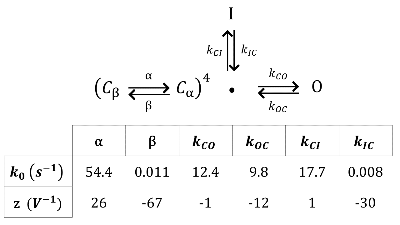
If channel opening and closing was much faster than all other time scales in the system, would simply be the equilibrium open probability at the present voltage: Ariyaratne and Zocchi (2016). However, this is not the case and one has to consider channel dynamics, which in HH is represented by a set of rate equations. The standard model has 3 states with respect to conduction: Closed, Open (probability ), Inactive (probability ), and several “internal” states. Namely, the ion channel being a tetramer, each subunit is assigned two states, and . The closed state that is accessible to the open and inactive states requires all 4 subunits be in the state, associated with probability . Probabilities , , and are associated with states inaccessible to the open and inactive states. These probabilities correspond to 3, 2, 1, and 0 subunits in the state, respectively (more details are given in Supplementary Materials). The dynamics of is then given by the rate equations Hille ; Sakmann and Neher (2009):
| (3) |
and eqs. (2) and (3) constitute the model. For the voltage dependence of the rates in (3) one takes exponential (Arrhenius) functions; the corresponding parameters have indeed been measured for KvAP Schmidt et al. (2009). We use parameters that best fit our system.
In Fig. 6, the fit superimposed on the measured voltage trace shows an example
of reproducing the dynamics seen in the experiments using this model. There are two interesting aspects. One is that the model can be used as an engineering tool to predict how more complicated
configurations of artificial axons will behave. The other is the nonlinear dynamics of this
interesting complex system, which however, has been studied Koch (1999).
Discussion. The artificial axon represents an experimentally controlled, synthetic realization of this most
interesting of nonlinear dynamical systems, the excitable cell.
It is to our knowledge the first artificial system based on the bio-components that generates
something similar to action potentials. Even in its present simple form it can
serve as a breadboard for electrophysiology measurements which does not involve lab animals. For example,
the electrophysiology of real neurons is extremely temperature dependent Hodgkin and Katz (1949); SM et al. (1985); future experiments with the artificial axon may elucidate the causes.
Networks of excitable nodes are intensively studied computationally Larremore et al. (2014). What is the outlook for a network of artificial axons? On the positive side there are power and space
considerations. Reasoning on a hypothetical membrane patch with
channels, responding on a time scale (our present axon is larger:
, and slower: , but size can be reduced and much
faster channels than the KvAP are available, so the above are by no means unrealistic conditions), the
capacitance is and it takes only the transfer of charges to step
the voltage by , giving a dissipation of over , or
. One can certainly imagine a size chip containing membrane
patches. For comparison, our brain has neurons and consumes , or
per neuron, though only a fraction of this dissipation is due to action potentials.
A flip-flop circuit in a CPU (consisting of transistors) consumes at
or at . This factor in power dissipated
compared to our hypothetical membrane patch
comes essentially from the factor reduction in operating voltage:
between transistors and voltage gated channels. The biological channels are the much sought for
low voltage transistors! Indeed, this mismatch is the main problem while interfacing “bare” electronic
components with the artificial axon; for instance, in order to make a one-way synapse one cannot
simply connect two axons through a diode, because of the voltage drop across the diode.
Now on the negative side, for a viable network there are problems to be solved requiring altogether
new inventions. The first is scaling up the system, introducing two channel species, and obtaining the
necessary robustness. Another challenge is creating an artificial electrochemical synapse which uses
only low voltage components. In the next decades, we look forward to progress being made on both fronts.
I Acknowledgements
We thank Roderick MacKinnon for the original gift of the KvAP plasmid, and Amila Ariyaratne for invaluable advice and support. This work was supported by NSF grant DMR-1404400.
References
- Koch (1999) Christof Koch, Biophysics of Computation (Oxford Univ. Press, 1999).
- (2) Bertil Hille, Ion channels of excitable membranes (3rd edition, ISBN-10: 0878933212).
- Ariyaratne and Zocchi (2016) Amila Ariyaratne and Giovanni Zocchi, “Toward a minimal artificial axon,” J. Phys. Chem. B 120, 6255 (2016).
- Feinerman et al. (2008) Ofer Feinerman, Assaf Rotem, and Elisha Moses, “Reliable neuronal logic devices from patterned hippocampal cultures,” Nature Physics 4, 967–973 (2008).
- Mueller et al. (1962) Paul Mueller, Donald O. Rudin, H. Ti Tien, and William C. Wescott, “Reconstitution of cell membrane structure in vitro and its transformation into an excitable system,” Nature 194, 979 – 980 (1962).
- Schmidt et al. (2009) Daniel Schmidt, Samuel R. Cross, and Roderick Mackinnon, “A gating model for the archeal voltage-dependent k+ channel KvAP in DPhPC and POPE:POPG decane lipid bilayers,” J. Mol. Biol. 390 (2009).
- Aimon et al. (2011) Sophie Aimon, John Manzi, Daniel Schmidt, Jose Antonio Poveda Larrosa, Patricia Bassereau, and Gilman E. S. Toombes, “Functional reconstitution of a voltage-gated potassium channel in giant unilamellar vesicles,” PLoS ONE 6, e25529 (2011).
- Ariyaratne and Zocchi (2013) Amila Ariyaratne and Giovanni Zocchi, “Nonlinearity of a voltage gated potassium channel revealed by the mechanical susceptibility,” Phys. Rev. X 3, 011010 (2013).
- Ruta et al. (2003) Vanessa Ruta, Youxing Jiang, Alice Lee, Jiayun Chen, and Roderick MacKinnon, “Functional analysis of an archaebacterial voltage-dependent channel,” Nature 422, 180–185 (2003).
- Sakmann and Neher (1984) B. Sakmann and E. Neher, “Patch clamp techniques for studying ionic channels in excitable membranes,” Ann. Rev. Physiol. 46, 455–72 (1984).
- Salman et al. (1996) Hanna Salman, Yoav Soen, and Erez Braun, “Voltage fluctuations and collective effects in ion-channel protein ensembles,” Phys. Rev. Lett. 77, 4458 (1996).
- Salman and Braun (1997) Hanna Salman and Erez Braun, “Voltage dynamics of single-type voltage-gated ion-channel protein ensembles,” Phys. Rev. E 56, 852 (1997).
- Sakmann and Neher (2009) Sakmann and Neher, Single-Channel Recording (Springer, 2nd edition, ISBN: 9781441912305, 2009).
- Hodgkin and Katz (1949) L. Hodgkin and B. Katz, “The effect of temperature on the electrical activity of the giant axon of the squid,” J. Physiol. 109, 240–49 (1949).
- SM et al. (1985) Thompson SM, Masukawa LM, and Prince DA, “Temperature dependence of intrinsic membrane properties and synaptic potentials in hippocampal ca1 neurons in vitro,” Neurosci. 5, 817–24 (1985).
- Larremore et al. (2014) Daniel B. Larremore, Woodrow L. Shew, Edward Ott, Francesco Sorrentino, and Juan G. Restrepo, “Inhibition causes ceaseless dynamics in networks of excitable nodes,” Phys. Rev. Lett. 112, 138103 (2014).
Supplemental Materials
II Materials and Methods
We use a voltage gated potassium ion channel from the thermophilic bacterium Aeropyrum pernix (KvAP). The channel is closed at large negative voltages; the midpoint of the open probability curve is at , and the open channel conductance is [8, 9]. KvAP has a slow dynamics of inactivation; to recover from inactivation, it must be held at voltages below .
Vesicles and decane lipid membranes are made with the phospholipid DPhPC.
II.1 A. Expression and Reconstitution
KvAP protein expression, purification and reconstitution mostly follow the protocols in [9], and are described at length in [8]. Briefly, the KvAP gene in vector pQE60 is expressed in E. coli cells (Aligent XL-1 Blue). Vector transformation into E. coli is achieved with a 45 second, 42 degree heat pulse. Cells with KvAP protein are re-suspended in buffer and lysed in a homogenizer (Avestin EmulsiFlex-C3). Protein is extracted from the lysate with decylmaltoside detergent (DM, Anatrace) and centrifugation. Talon nickel bead resin (Clonetech) is added to the his-tagged ion channel solution for binding and purification. The mixture is passed through a Talon affinity column then eluted. The elution is treated with thrombin to remove the his-tag from the ion channel. Thrombin and his-tag are removed from the sample by size exclusion chromatography (GE Healthcare, Superdex-200).
DPhPC is suspended in buffer and sonicated to produce uni-lamellar vesicles. The protein sample is added to the vesicle solution then passed through 3 spin desalting columns (Thermo Scientific, Zeba) to remove most DM from solution. DM in complexes with lipid are removed with detergent absorbing bio beads (Bio-Rad). After DM removal, the vesicle-channel solution is aliquoted and flash frozen in an ethanol-dry ice bath, then stored at -80 C.
II.2 B. Electrophysiology Setup
Overall setup, including headstage and voltage amplifiers are described at length in publications [3] and [8], and data acquisition is described in publication [3]. Setup and components will be described briefly.
A aperture on a plastic cup is used as the support for a decane lipid membrane. The membrane separates two chambers of different concentrations. One chamber is grounded, through an Ag/AgCl electrode. The other contains two Ag/AgCl electrodes (see Fig. 1), one for the current limited voltage clamp (CLVC), the other connecting to: 1) an amplifier for the measurement of the axon voltage ; 2) an independent current clamp used to inject a stimulus current; 3) the input of the electronic synapse feeding into axon 2 (for the two-axons experiment). For the CLVC, we use the resistor values and for different situations. For the two-axon measurements, both wells are connected to independent CVLC’s. All electronics are made in-house.
The electronic synapse connecting two axons is a current clamp. The membrane voltage of axon 1 is the command voltage for the synapse, effectively assigning axon 1 the role of the pre-synaptic neuron. The synapse can inject current into well 2 only when . This switch behavior is achieved with a solid state relay [3] that is switched to open/close with an op-amp. Positive/negative controls the polarity of op-amp saturation, which in turn switches the relay to the open/close position. Design figures and detailed descriptions are to be provided in later publications.
II.3 C. Modeling
The scheme for KvAP gating used to fit the channel behavior is from [6]. We used as a guideline the rate constants in [6] for DPhPc lipid membranes, with modifications to fit our data. All rate constants have the form . The gating scheme and , z values are provided in Supplemental Material Figure 1.