Computational modelling of hydrogen assisted fracture in polycrystalline materials
Abstract
We present a combined phase field and cohesive zone formulation for hydrogen embrittlement that resolves the polycrystalline microstructure of metals. Unlike previous studies, our deformation-diffusion-fracture modelling framework accounts for hydrogen-microstructure interactions and explicitly captures the interplay between bulk (transgranular) fracture and intergranular fracture, with the latter being facilitated by hydrogen through mechanisms such as grain boundary decohesion. We demonstrate the potential of the theoretical and computational formulation presented by simulating inter- and trans-granular cracking in relevant case studies. Firstly, verification calculations are conducted to show how the framework predicts the expected qualitative trends. Secondly, the model is used to simulate recent experiments on pure Ni and a Ni-Cu superalloy that have attracted particular interest. We show that the model is able to provide a good quantitative agreement with testing data and yields a mechanistic rationale for the experimental observations.
keywords:
Phase field , Hydrogen embrittlement , Cohesive Zone Model , Elasto-plastic fracture , Finite Element Method1 Introduction
Hydrogen is at the core of the most promising solutions to our energy crisis. Hydrogen isotopes fuel the nuclear fusion reaction, the most efficient potentially useable energy process. Moreover, hydrogen is widely seen as the energy carrier of the future and the most versatile means of energy storage. It can be produced via electrolysis from renewable sources, such as wind or solar power, and stored to be used as a fuel or as a raw material in the chemical industry. Hampering these opportunities, hydrogen is known for causing catastrophic failures in metallic structures. Through a phenomenon often termed hydrogen embrittlement, metals exposed to hydrogen containing environments experience a significant reduction in ductility, fracture toughness and fatigue resistance [1, 2, 3]. In the presence of hydrogen, otherwise ductile metals fail in a brittle manner, with cracking often nucleating and propagating along grain boundaries [4, 5]. This ductile-to-brittle shift of metallic alloys in hydrogeneous environments is arguably one of the biggest threats to the deployment of a hydrogen energy infrastructure.
There is a vast literature devoted to shed light into the physical mechanisms behind hydrogen embrittlement [6, 7, 8, 9, 10, 11], and to develop mechanistic predictive models that can prevent failures and map safe regimes of operation [12, 13, 14, 15, 16]. The vast majority of the computational models developed for predicting hydrogen assisted cracking fall into two categories: (i) discrete methods, such as cohesive zone models [17, 18, 19, 20], and (ii) diffuse approaches, such as phase field or other non-local damage models [21, 22, 23, 24, 25, 26]. Cohesive zone models and other discrete methodologies are suitable to describe the nucleation and propagation of sharp cracks through a predefined path. Phase field fracture methods have additional modelling capabilities and can also deliver predictions when the crack trajectory is unknown, when failure is triggered by defects of arbitrary shape, and when the fracture process is complex (e.g., involving the interaction between multiple defects). Both kinds of models can be readily coupled with the hydrogen transport equation and have been successful in qualitatively capturing the main experimental trends, such as the sensitivity to loading rate, hydrogen concentration, and material strength. However, these modelling studies treat materials as isotropic continuum solids, without resolving the underlying microstructure. A number of icrostructurally-sensitive works have been recently carried out (see, e.g., [27, 28, 29, 30, 31, 32, 33] and Refs. therein), but these are limited to capture the interplay between diffusion and deformation, and do not explicitly simulate fracture. The micromechanical fracture of polycrystalline materials in hydrogen-containing environments has been simulated in the works of Rimoli and Ortiz [34], Benedetti et al. [35], and De Francisco et al. [36]. In these works, a cohesive zone formulation was used to predict the failure of grain boundaries, neglecting transgranular cracks.
In this work, we present a new microstructurally-sensitive computational framework for predicting hydrogen assisted fractures. For the first time, the model combines a phase field description of bulk fracture with a cohesive zone model for intergranular cracking. This enables capturing both ductile transgranular fracture and brittle intergranular fracture, and the transition from one to the other. The mechanical and hydrogen transport problems are strongly coupled, with the hydrostastic stress driving hydrogen transport and the hydrogen content reducing the grain boundary strength. The fracture of polycrystalline solids is simulated, with the bulk deformation response being characterised by von Mises plasticity theory. Numerical experiments are conducted to gain insight into the mechanisms of hydrogen-assisted grain boundary decohesion. Focus is on Ni and Ni superalloys, where hydrogen assisted failures are known to be governed by grain boundary decohesion [4, 37]. Among other case studies, the model is used to provide a mechanistic rationale to two recent sets of experiments on Monel K-500 [38] and pure Ni [4] that have attracted particular interest in the hydrogen embrittlement community.
2 Modelling framework
2.1 Fundamentals
Our model deals with an arbitrary body with a delimiting external surface of outward normal n. The body contains a discrete internal discontinuity associated with fracture events in the bulk, and also pre-existing interfaces, arranged in the set . Through exposure to a hydrogen containing environment, hydrogen ingress takes place and thus hydrogen atoms can diffuse through the body, driven by gradients of chemical potential. As detailed in the forthcoming subsections, this leads to a three-field boundary value problem, where the displacement field, the fracture status, and the hydrogen concentration are the primal kinematic variables.
We build our framework upon the assumption of small strains. The vector is used to denote the position of an arbitrary point in the global Cartesian system. From a mechanical perspective, the delimiting surface of the body is decomposed into two regions; one where the displacements u are prescribed through Dirichlet-type boundary conditions (BCs), , and one where tractions t are prescribed via Neumann-type BC, such that and . The deformation process is characterized by the small deformation tensor , which is defined as the symmetric part of the displacement gradient: . Bulk fracture phenomena is here captured using the phase field fracture method [39, 40]. Hence, crack discontinuities are regularised within a diffuse region, whose thickness is characterised by a phase field length scale , and the evolution of the crack-solid interface is described by an auxiliary phase field variable . Regarding hydrogen transport, the external body surface is divided into two parts: the region , where the hydrogen flux can be prescribed through a Neumann-type BC, and the region where the hydrogen concentration can be prescribed using a Dirichlet BC.
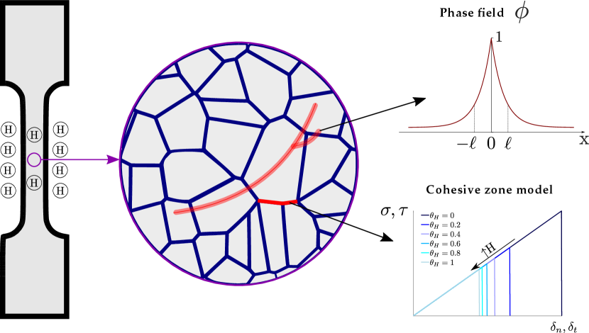
In addition to bulk fracture, our microstructurally-sensitive formulation employs a cohesive zone model to describe the failure of grain boundaries. As shown in Fig. 1, we explicitly model the polycrystalline microstructure of metals and predict intergranular and transgranular cracking events. The phase field fracture method is used to describe transgranular cracks, which are associated with a ductile fracture process, while a cohesive zone model is employed to predict the decohesion of grain boundaries. Since the latter correspond to a brittle failure and are triggered by the presence of hydrogen, the interfacial fracture energy is defined as a function of the hydrogen concentration . Conversely, the bulk material toughness is considered to be a hydrogen-insensitive constant that characterises the resistance of the material to undergo microvoid cracking. Accordingly, for a solid with strain energy density , the internal functional of the mechanical system comprises the bulk () and interfacial () contributions, reading
| (1) |
In the subsequent subsections we proceed to describe each of the features and the constitutive choices of our micromechanical model.
2.2 Chemo-elastoplasticity
The deformation and diffusion problems are intrinsically coupled as hydrogen transport within the crystal lattice is driven by gradients of concentration and hydrostatic stress. We focus our attention on the transport of diffusible hydrogen and consider the influence of traps in the cracking process by using the Langmuir-Mclean isotherm to estimate the hydrogen coverage at grain boundaries. The role of microstructural traps upon slowing down diffusion can also be taken into account through an appropriate choice of the (apparent) diffusion coefficient . Mass conservation requirements relate the rate of change of the hydrogen concentration to the hydrogen flux through the external surface,
| (2) |
The strong form of the balance equation can be readily obtained by making use of the divergence theorem and noting that the expression must hold for any arbitrary volume,
| (3) |
For an arbitrary, suitably continuous, scalar field, , the variational statement (3) reads,
| (4) |
Rearranging, and making use of the divergence theorem, the weak form renders,
| (5) |
where is the concentration flux exiting the body across . The diffusion is driven by the gradient of the chemical potential , with the chemical potential of hydrogen in lattice sites being given by,
| (6) |
Here, is the occupancy of lattice sites, which is related to the concentration and number of sites as . Also, denotes the chemical potential in the standard case, and is the hydrostatic stress. The last term of (6) corresponds to the so-called stress-dependent part of the chemical potential , with being the partial molar volume of hydrogen in solid solution. The mass flux follows a linear Onsager relationship with , which is often derived from (6) by adopting the assumptions of low occupancy () and constant interstitial sites concentration () (see, e.g., [41, 42]), such that
| (7) |
where is the absolute temperature and is the ideal gas constant. Accordingly, the hydrogen transport equation becomes
| (8) |
As evident from (6)-(8), the presence of hydrostatic stresses (or volumetric strains) brings a reduction in chemical potential and an increase in hydrogen solubility. Thus, an appropriate description of the stress state in the solid is needed to quantitatively estimate the hydrogen distribution. Here, we choose to describe the deformation of the solid using conventional von Mises plasticity. Accordingly, the total strain energy density of the solid is given by the sum of the elastic and plastic parts,
| (9) |
where is the first Lame parameter and is the shear modulus. Also, the Cauchy stress tensor is given by , and and respectively denote the elastic and plastic strain tensors. Isotropic power law hardening behaviour is assumed by adopting the following hardening law:
| (10) |
where and are the current and initial yield stresses, is Young’s modulus, is the accumulated equivalent plastic strain and is the strain hardening exponent. One should note that, for simplicity, we have chosen to neglect the role of plastic strain gradients; however, large plastic strain gradients arise in the vicinity of cracks and other stress concentrators and lead to large crack tip tensile stresses and hydrogen concentrations [43, 44]. The extension of the present framework to account for the role of plastic strain gradients and geometrically necessary dislocations (GNDs) will be addressed in future work.
2.3 A phase field description of transgranular fractures
The phase field fracture method is used to regularise the internal discontinuity , representing the nucleation and growth of transgranular (ductile) cracks. An auxiliary phase field variable is used to describe the evolution of the solid-crack interface, taking the value of for the pristine state and of for the fully damaged state. Phase field fracture methods have gained remarkable popularity in recent years and have been successfully used to predict cracking in a wide range of materials and applications, including functionally graded solids [45, 46], shape memory alloys [47, 48], and fibre-reinforced composites [49, 50]. The evolution of the phase field equation is dictated by the energy balance associated with the thermodynamics of fracture, as first presented by Griffith [51] and later extended to elastic-plastic solids by Orowan [52]. Thus, under prescribed displacements, the variation of the total energy due to an incremental increase of the crack area d is given by,
| (11) |
where is the work required to create two new surfaces and is the stored strain energy. The last term in Eq. (11) denotes the material toughness , which can be as low as some tens of J/m2 for brittle solids or as high as thousands of kJ/m2 for ductile metals where plastic dissipation enhances fracture resistance. The energy balance of Eq. (11) can be cast in a variational form as [53]:
| (12) |
The energy balance is now global and fracture phenomena can be predicted by minimizing the total energy . However, minimization of Eq. (12) is hindered by the unknown nature of the discontinuous crack surface . The phase field regularization can then be exploited to smear this sharp interface into a diffuse region, whose thickness is governed by a phase field length scale . Accordingly, the energy balance (12) can be approximated as [39]:
| (13) |
where is the so-called crack density functional and is the degradation function. We choose to adopt the standard or AT2 phase field formulation [39], and accordingly make the following constitutive choices,
| (14) |
| (15) |
where is a small numerical parameter to retain residual stiffness when , so as to avoid an ill-conditioned system of equations. Noting that , the strong form of the coupled deformation-fracture problem can be readily obtained by inserting (14)-(15) into (13), taking the variation with respect to and , and applying Gauss theorem. However, such a formulation would predict cracking also under compressive stress states. Hence, we adopt the so-called volumetric-deviatoric split [54] to decompose the elastic strain energy density into a tensile part,
| (16) |
and a compressive part,
| (17) |
Here, is the bulk modulus, is the trace operator, and . Furthermore, a history field is defined to enforce damage irreversibility. Among the various choices available (see, e.g., [55, 56]), we choose to assume that fracture is driven by the energy stored in the system, in consistency with the energy balance above [40]; accordingly: . The local governing equations then read,
| (18) |
| (19) |
2.4 Hydrogen-sensitive interface formulation for grain boundaries
In this modelling framework, the polycrystalline nature of the material is resolved and the decohesion of grain boundaries is explicitly captured by means of a cohesive zone model. Specifically, a traction-separation law is adopted that assumes a tension cut-off relation [58]. This interface formulation assumes a linear and reversible (elastic) evolution until the critical traction is reached. The damage criterion relates the normal and tangential tractions with their critical counterparts as follows,
| (20) |
Accordingly, a critical normal and shear separations can be defined, which leads to the following definitions of fracture energy for Mode I and Mode II fractures
| (21) |
As sketched in Fig. 1, the role of hydrogen in weakening the grain boundaries is accounted for by degrading the interface fracture energy. Thus, the focus here is on materials that exhibit hydrogen assisted intergranular fracture, such a Ni and Ni alloys [4]. Atomistic calculations have shown a linear relationship between the surface (or fracture) energy and the hydrogen coverage (see, e.g., [59, 60]). Accordingly, and following Martínez-Pañeda et al. [21], we define the following relationship between the fracture energy and the hydrogen coverage ,
| (22) |
where is the fracture energy in the absence of hydrogen and is the so-called hydrogen damage coefficient [21]. The same expression is employed for and . Finally, the hydrogen coverage is estimated from the hydrogen concentration by means of the Langmuir-McLean isotherm:
| (23) |
where is the Gibbs free energy difference between the interface and the surrounding material, also referred to as the segregation energy. Unless indicated otherwise, a value of is here employed, based on the spectrum of experimental data available for the trapping energy at grain boundaries [21, 17].
2.5 Numerical implementation
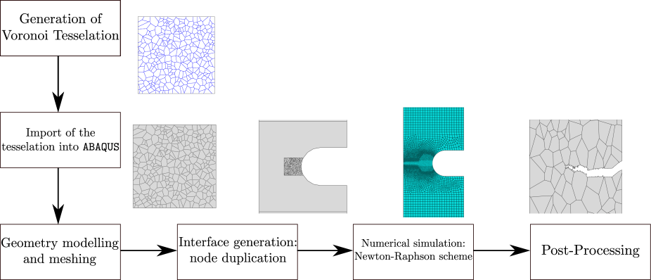
The theoretical model presented in Sections 2.1 to 2.4 is numerically implemented by means of the finite element method. Specifically, the model is implemented in the commercial finite element package ABAQUS/Standard via a user element (UEL) subroutine. In addition, the Abaqus2Matlab software [61] is used to generate the input files and the MATLAB supplementary codes given in Ref. [62] are used to generate the microstructure. Fig. 2 provides a flowchart of the steps followed in the definition and analysis of the microstructure sensitive boundary value problems investigated. Specifically, the microstructure is generated by using a Voronoi-based tessellation algorithm, programmed in MATLAB [62], and this step is followed by the introduction of the resulting microstructure into the ABAQUS input file using a Python script. The coupled deformation-diffusion-fracture system is solved in a staggered fashion, with every sub-problem being solved by means of a backward Euler solution scheme. Typical calculation times are of a few hours.
3 Results
The potential of the theoretical and computational framework presented in Section 2 shall be demonstrated through representative case studies. First, in Section 3.1, a benchmark example is analysed, whereby cracking is predicted in a single edged notched tension specimen containing 50 grains and exposed to various hydrogen-containing environments. Second, we simulate recent slow strain rate tests (SSRTs) on different Monel K-500 lots in Section 3.2, so as to assess the ability of the model in providing a quantitative agreement with experiments and shedding light into the suitability of SSRTs to measure hydrogen susceptibility. Finally, in Section 3.3, the model is used to simulate, for the first time, the seminal experiments by Harris et al. [4] on pure Ni under cryogenic and ambient temperature conditions.
3.1 Benchmark: fracture of a 50-grain SENT plate
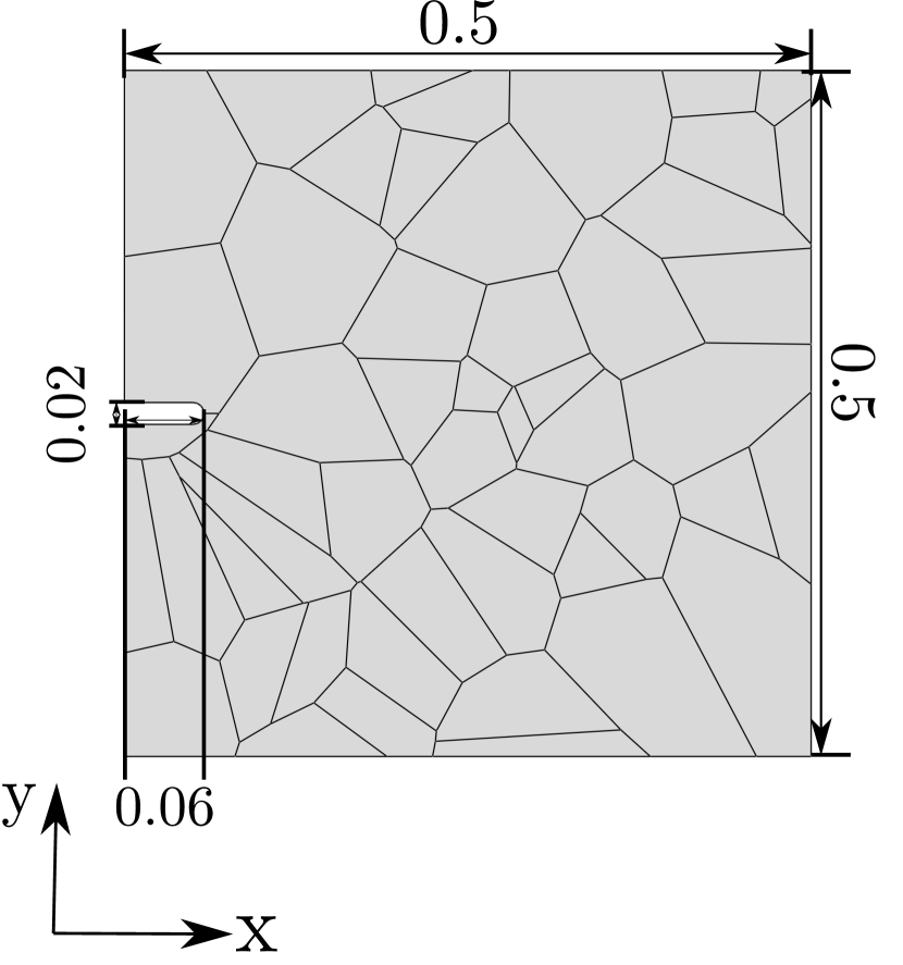
Crack nucleation and growth in a square plate microstructure of 50 grains is investigated. The plate, with dimensions given in Fig. 3.1a, contains a small notch and is subjected to uniaxial loading; a testing configuration often referred to as single edge notched tension (SENT) specimen. The load is applied by prescribing the vertical displacement at the upper edge, at a rate of mm/s, while the vertical displacement is constrained at the bottom edge. To prevent rigid body motion, the horizontal displacement is constrained at the bottom-right corner. The sample is exposed to hydrogen on its left side, where the notch is located. No pre-charging time in considered, with both hydrogen and mechanical charging starting simultaneously. The magnitude of the environmental hydrogen concentration is varied between 0 and 0.9 ppm wt with the aim of capturing a reduced critical load with increasing hydrogen content, and a transition from ductile (bulk) fracture to intergranular cracking. The material properties assumed for the bulk and the interface are given in Table 1. The sample is discretised using a total of 48,554 quadratic quadrilateral elements.
| Bulk properties | ||||||
| n | ||||||
| 185 | 0.3 | 0.025 | 0.05 | 794.3 | 0.064 | |
| Interface properties | ||||||
| 0.86 | ||||||
The results obtained for the case of ppm wt are shown in Figs. (3.1b-3.1g), in terms of the phase field contours. In the absence of hydrogen, the crack nucleates inside of the grain, in the vicinity of the notch tip, and propagates in a transgranular manner. The damage appears to accumulate within the grain region closer to its boundary, as a stress mismatch takes place between adjacent grains due to differences between the stiffness of the bulk and that of the interface.
#
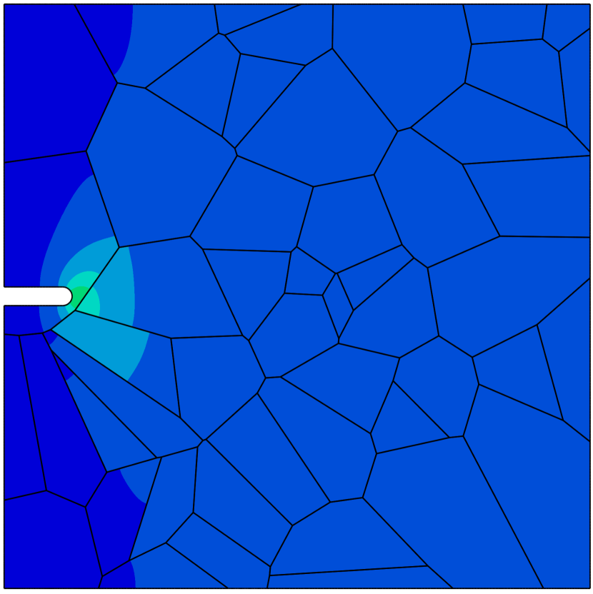
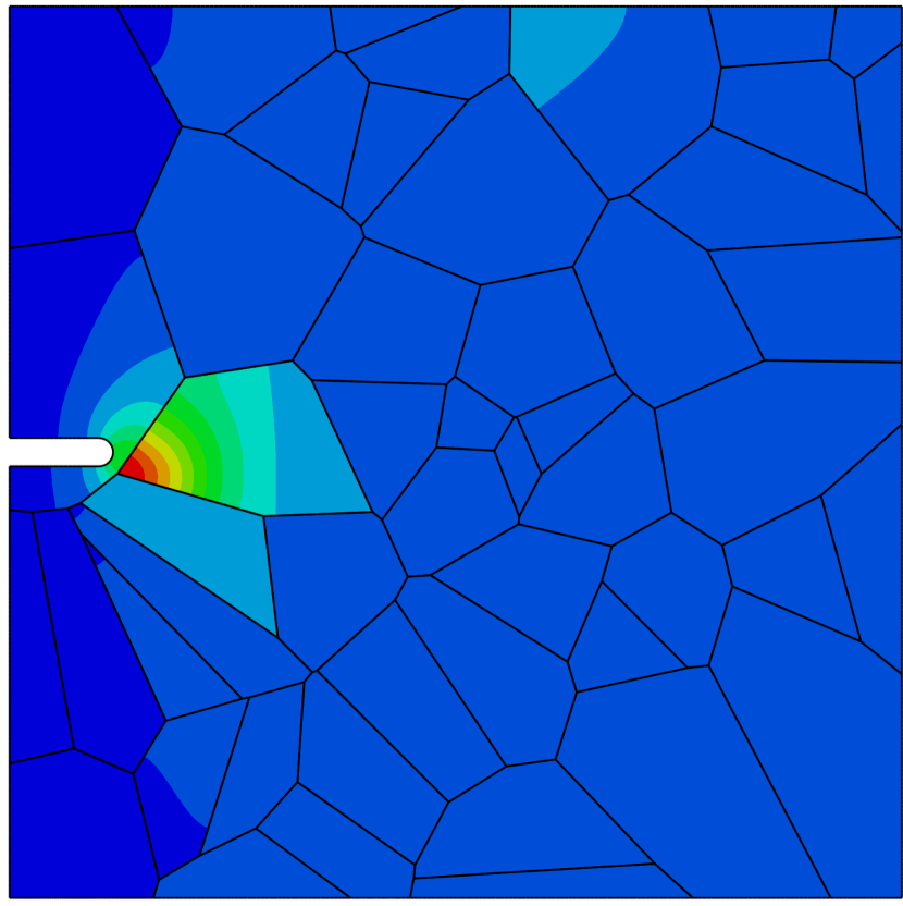
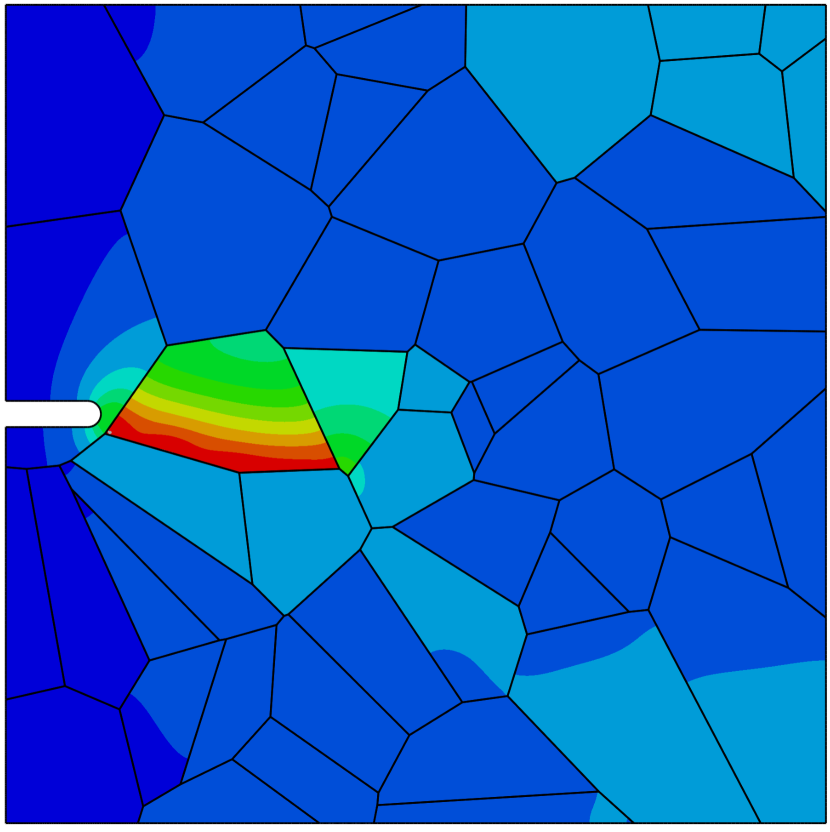
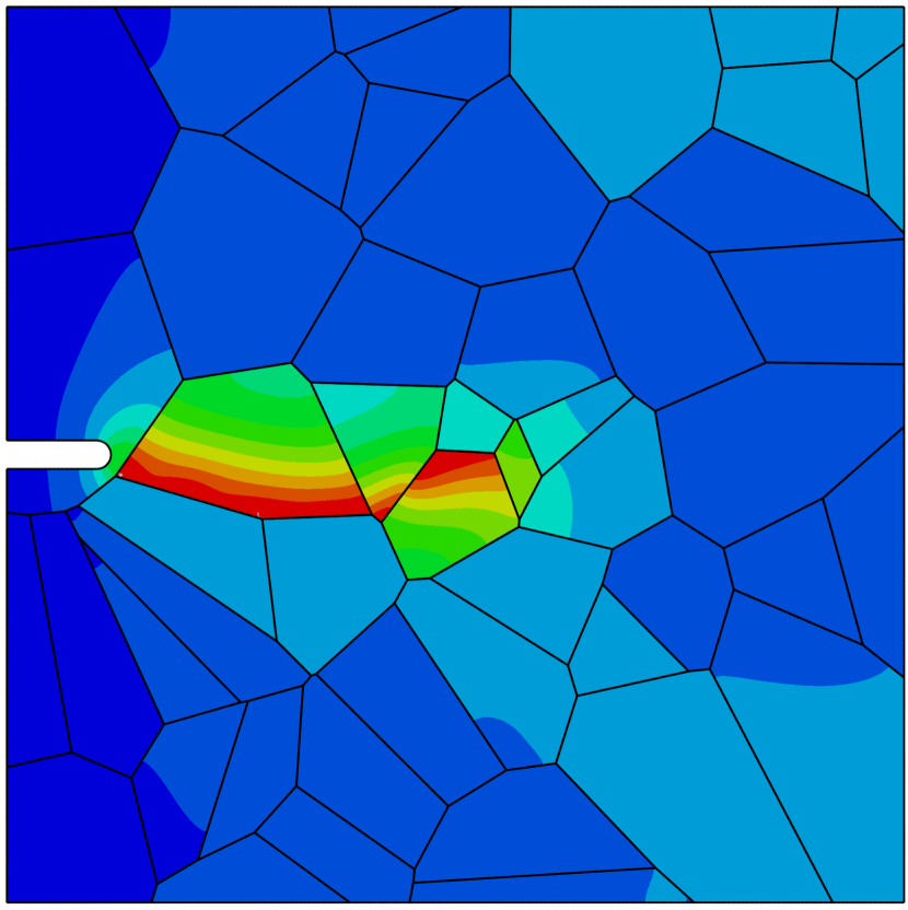
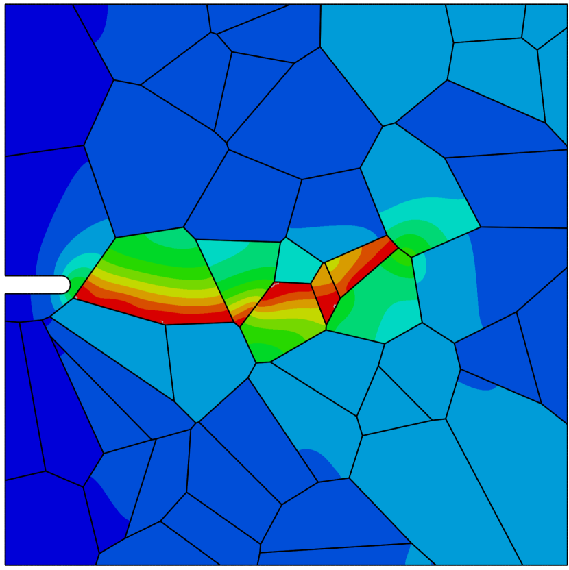
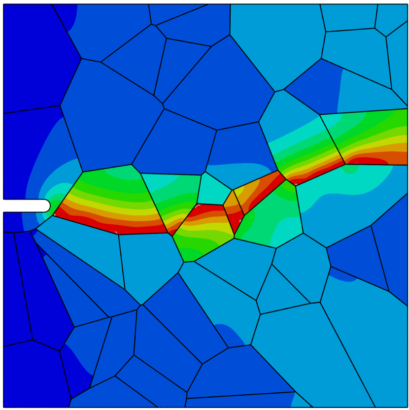
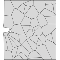
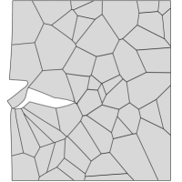
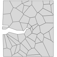
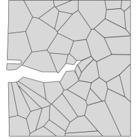
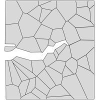
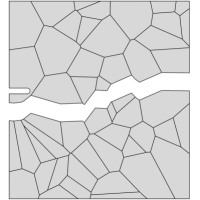
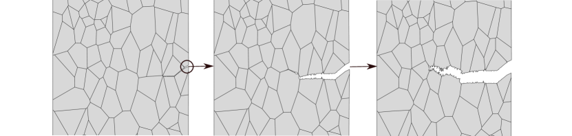
Contrarily, when the sample is exposed to hydrogen, cracking initiates along the grain boundaries and propagates in an intergranular manner. This is shown in Fig. 4, where the deformation and separation of the grains is shown as a function of the applied displacement for the case of ppm wt. The crack nucleates close to the notch, where both hydrogen content and tensile stresses are large (see Fig. 4a). As the remote load increases, the crack spreads to neighboring grain boundaries (Figs. 4b-e) and eventually leads to the complete failure of the specimen (Fig. 4f). Thus, by comparing Figs. 3.1 and 4, one can see that the model captures the ductile (transgranular) to brittle (intergranular) transition typically observed in the presence of hydrogen. In the absence of hydrogen, the strength of the grain boundaries is sufficiently large for failure to be driven by other mechanisms, encapsulated here in the phase field fracture model. However, when there is sufficient hydrogen in the sample, the grain boundaries experience a drop in strength that leads to an early nucleation and growth of intergranular cracks.
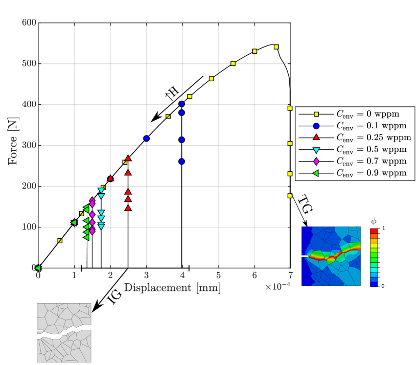
Finally, the resulting force versus displacement curves are shown in Fig. 5. The result shows that the model not only captures the shift in cracking patterns but can also predict the progressive degradation of fracture properties with increasing hydrogen content. Furthermore, the results also showcase the robustness of the numerical model, as the entire fracture process can be captured, until the complete rupture and loss of load carrying capacity.
3.2 Virtual slow strain rate testing on Monel K-500 samples
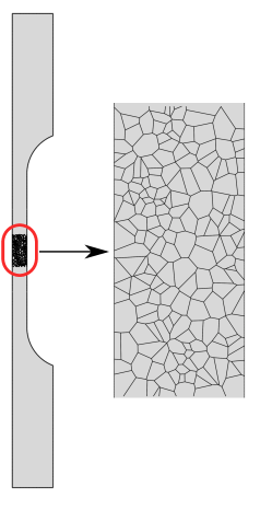
Recent slow strain rate tests (SSRTs) on a Ni–Cu superalloy (Monel K-500) have revealed significant intergranular cracking depths, much larger than those expected from diffusion calculations for relevant exposure times [38]. Hence, these experiments suggest that crack initiation is likely to take place much before final failure, allowing for the hydrogen-containing solution to reach significant depths by following the crack. Early sub-critical crack growth would imply the need for a fracture analysis, compromising the suitability of the SSRT experiment and its metrics (e.g., time to failure) in assessing hydrogen embrittlement susceptibility. The micromechanical formulation presented can be used to gain complementary insight into these paradigmatic experiments and the early cracking hypothesis. Mimicking the testing conditions, notched cylindrical specimens with the dimensions shown in Fig. 6a are considered in our simulations. The samples are subjected to uniaxial loading and thus one can take advantage of axially symmetric conditions. Accordingly, the sample is discretised using axisymmetrical finite elements; a total of 64,835 quadratic elements are employed. A microscopic region is introduced near the notch, see Fig. 6b. This region spans a width of 0.5 mm and includes 280 grains, while the remaining part of the solid is modelled as an isotropic continuum without interfaces. In this way, the model can capture the two cracking modes observed in the experiments; in the absence of hydrogen, cracking occurred at the centre of the sample due to plastic instabilities, while in the presence of hydrogen, cracking took place near the notch tip and was of intergranular nature [38].


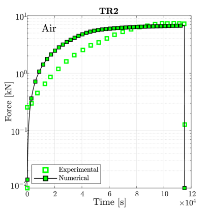
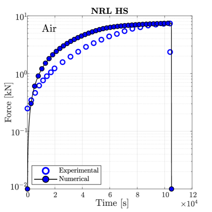
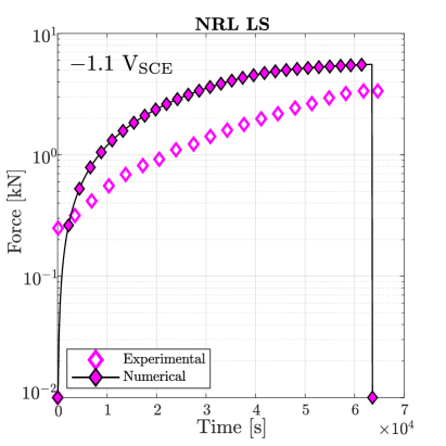
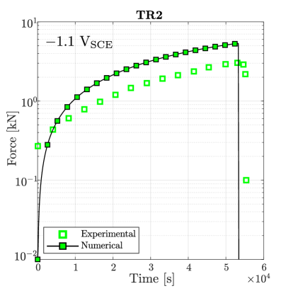
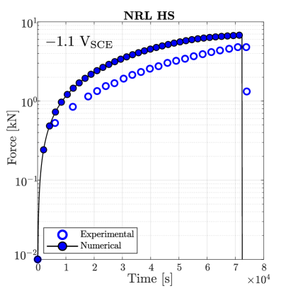
As in the experiments, the remote vertical displacement is applied at the top edge with a rate of . On the other hand, both vertical and horizontal displacements are constrained at the bottom edge. Also mimicking the experimental campaign, four Monel K-500 material heats were considered (Allvac, NRL LS, TR2 and NRL HS), with their macroscopic properties being given in Table 2. The reader is referred to Ref. [38] for a comprehensive description on the different ageing and heat treatments employed for each lot. The phase field length scale is assumed to be equal to and the material diffusivity equals [38]. The remaining fracture properties for the bulk and interface are calibrated as follows. First, is chosen so as to reproduce the experimental force versus time response in air. Then, the cohesive interface parameters and the hydrogen damage coefficient are calibrated with the experiments conducted at the most aggressive conditions (applied potential of V), and subsequently used to evaluate their predictive capabilities in other scenarios (different values).
| Heat | n | |||
|---|---|---|---|---|
| Allvac | 180 | 0.3 | 794.3 | 0.058 |
| NRL LS | 198 | 0.3 | 715.7 | 0.054 |
| TR2 | 202 | 0.3 | 795 | 0.055 |
| NRL HS | 191 | 0.3 | 910.1 | 0.050 |
Each Monel K-500 heat was tested in four different environments: in air (i.e., in the absence of a hydrogen-containing solution) and while being exposed to solutions with the applied potentials V, V, and V. The diffusible hydrogen concentration associated with each charging condition was experimentally measured and used as input in the model - a prescribed magnitude at the surface. The values measured are given in Table 3 (in ppm wt).
| Heat | |||
|---|---|---|---|
| Allvac | 1.9 | 4.1 | 7.5 |
| NRL LS | 1.3 | 4.7 | 18.3 |
| TR2 | 3.7 | 18.6 | 26.2 |
| NRL HS | 4.7 | 11.9 | 23.4 |
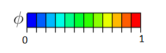
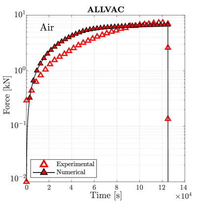
Simulations are first conducted in the absence of hydrogen. As shown in Fig. 7, damage initiates at the centre of the sample for sufficiently large loads, in agreement with experimental observations. The material toughness for each Monel K-500 lot is chosen so as to quantitatively reproduce the macroscopic force versus time curve, with the fitted values being 18.5, 18.1, 15.4 and 16.9 kJ/m2 for, respectively, Allvac, NRL LS, TR2, and NRL HS. The force versus time curves obtained for each material lot are shown in Fig. 8. A good agreement is attained with experimental observations, with only small differences being observed in the early stages due to the additional compliance brought in by the machine displacement (an extensometer was not used [38]).
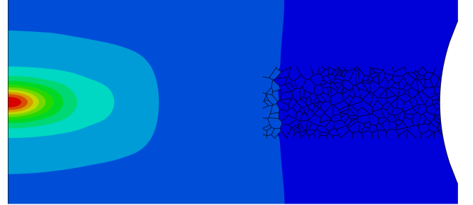
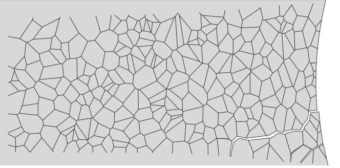
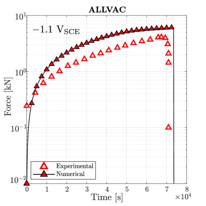
The samples with a higher degree of hydrogen uptake (those charged at V) exhibit an intergranular fracture pattern, as shown in Fig. 9. A crack nucleates in a grain boundary adjacent to the notch tip and subsequently propagates along neighboring grain boundaries. The force versus time curves obtained for the four material lots under an applied potential of V are shown in Fig. 10. In all cases the failure is intergranular, starting at the notch tip and triggering a significant drop in the load carrying capacity before any noticeable increase in the phase field variable is observed. Thus, the calibrated model is also able to capture the ductile-to-brittle transition observed in this case study.
Interestingly, the cracking event appears to occur rather suddenly, with the intergranular crack propagating into regions with low hydrogen content. This would suggest that the crack resulting from the decohesion of the grain boundaries exposed to a high hydrogen content would be sufficiently large to propagate in an unstable fashion through grain boundaries that have only been negligibly weakened by hydrogen. If that were to be the case, then these numerical results would suggest that SSRT is not compromised by early cracking and thus remains a valid test for measuring hydrogen embrittlement susceptibility. Additional, albeit limited, insight can be gained by a simple estimate of the transition flaw size . For Monel K-500 exposed to a relatively uniform hydrogen distribution resulting from an applied potential of V, the transition flaw size would be on the order of 0.04 mm (see Table 2 and the measurements of Ref. [7]). However, this quantity can increase to up to 4 mm in the absence of hydrogen. Thus, the magnitude of relevant to this scenario (a non-uniform distribution of hydrogen) falls between those two limiting cases, and could therefore be higher or lower than the crack extensions predicted (0.1-0.5 mm). Another source of uncertainty is the specific traction-separation law adopted, as assuming the existence of a damage dissipation region could add an additional source of fracture resistance.
The interface parameters that provide a quantitative agreement with experiments are given in Table 4. The damage coefficient was estimated based on previous (microstructurally-insensitive) phase field simulations [38]. The values of used are higher than those estimated using atomistic calculations for most common types of Ni grain boundaries [60]. However, the choices of values are notably sensitive to the magnitude of the grain boundary binding energy considered in (23), and the estimation of this magnitude carries a degree of uncertainty [63].
The calibrated model is used to reproduce the entire experimental campaign, conducting virtual experiments on the four material lots over the four environments considered. We summarise the outcome of the simulations in Table 5, indicating the failure model predicted (brittle integranular/IG or ductile transgranular/TG). Green check marks are used to denote when the predicted mode of cracking agrees with the experimental observation, with red crosses denoting otherwise. As observed, the model is capable of predicting the occurrence of hydrogen-assisted brittle failures in all but one case - the experiment on the NRL LS heat at V. As discussed in Ref. [38], this is a rare case as SEM images of the fracture region reveal intergranular features but the time to failure happens to be larger than that measured in the absence of hydrogen. It is thus concluded that the micromechanical model presented is capable of predicting hydrogen embrittlement upon appropriate calibration.
| Allvac | NRL LS | TR2 | NRL HS | |
| () | ||||
| () | ||||
| () | ||||
| 0.85 | 0.82 | 0.86 | 0.79 |
| Allvac | NRL LS | TR2 | NRL HS | |
|---|---|---|---|---|
| 0 (Air) | TG ✓ | TG ✓ | TG ✓ | TG ✓ |
| 0.85 | TG ✓ | TG | TG ✓ | - |
| 0.95 | TG ✓ | IG ✓ | IG ✓ | TG ✓ |
| 1.1 | IG ✓ | IG ✓ | IG ✓ | IG ✓ |
3.3 Failure of pure Ni samples at ambient and cryogenic temperatures
Finally, we employ the micromechanical cohesive zone - phase field formulation developed to shed light on the interplay between diffusion, deformation, temperature, and embrittlement on pure Ni. Harris et al. [4] investigated the contribution of mobile hydrogen-deformation interactions to hydrogen-induced intergranular cracking in polycrystalline Ni by testing hydrogen charged samples at both ambient (298 K) and cryogenic (77 K) temperatures. Their uniaxial mechanical tests showed that embrittlement (hydrogen-assisted intergranular cracking) occurred even at cryogenic temperatures, where dislocation-hydrogen interactions are precluded. This suggests that hydrogen-assisted decohesion of grain boundaries is a first-order mechanism in hydrogen embrittlement. It was also found that intergranular microcrack evolution was enhanced at room temperature, relative to 77 K, but a mechanistic interpretation of this finding was deemed complicated due to the multiple factors at play. Here, we examine the ability of our micromechanical model to quantitatively reproduce the seminal experiments by Harris et al. [4] and use the numerical insight provided to gain further understanding on the role of temperature in enhancing embrittlement. The material properties adopted correspond to those reported by Harris et al. [4], which are listed in Table 6 as a function of the temperature and the environment. Two environmental conditions are considered: (i) samples tested in air, without any hydrogen pre-charging, and (ii) samples exposed to a hydrogen content of 4000 appm (79.5 wppm). In the latter, gaseous hydrogen charging is used and the hydrogen is distributed uniformly within the samples. Mimicking the experimental conditions, the uniaxial load is prescribed by applying a remote vertical displacement with a rate of mm/s, while the bottom edge is completely constrained ().
| Temperature | 77 K | RT | ||
|---|---|---|---|---|
| no H | H | no H | H | |
| 227 | 227 | 202 | 202 | |
| 0.3 | 0.3 | 0.3 | 0.3 | |
| 222 | 233 | 182 | 192 | |
| 0.159 | 0.159 | 0.140 | 0.140 | |
The samples are cylindrical bars with the dimensions given in Fig. 11a. As in the previous case study, we take advantage of axial symmetry and model half of the 2D section using axisymmetric elements. A total of approximately 80,000 quadratic axisymmetric elements are used to discretise the model. As shown in Fig. 11b, we introduce a microstructural domain of 200 grains in the central region of the sample. The phase field length scale is taken to be equal to = 0.025 mm, and the toughness is calibrated to reproduce the experiments in the absence of hydrogen, rendering values of 4 kJ/m2 (77 K) and 2.5 kJ/m2 (RT). The interfacial cohesive properties are adjusted to reproduce the experiments at 77 K and then used to see if the results at room temperature can be predicted. The specific values used are given in Table 7 and, following the approach of Ref. [16], a phenomenological degradation law is adopted, such that
| (24) |
with the Gibbs free energy being equal to 17 kJ/mol [64].
| () | ||
|---|---|---|
As shown in Figs. 11 and 12, the model is able to reproduce experimental measurements beyond the regimes of calibration, both qualitatively and quantitatively. Consider first the cracking patterns shown in Fig. 11. In the absence of hydrogen (Fig. 11c), failure takes place due to the onset of ductile (transgranular) damage in the centre of the sample, as predicted by the phase field order

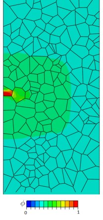
parameter. However, when the sample is exposed to hydrogen, then cracking takes place in an intergranular fashion, as a result of the failure of the cohesive zone interfaces. The location of the grain boundary decohesion event that nucleates the brittle crack is random. For the microstructure and conditions of Fig. 11d, it occurs close to the edge of the sample, with the crack growing then both towards the outer surface and towards the centre of the sample. This change from ductile transgranular damage to brittle intergranular cracking due to hydrogen is observed at both 77 and 298 K, as in the experiments.
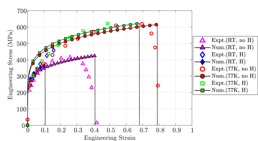
The quantitative results obtained for the four scenarios are shown in Fig. 12, in terms of the predicted and measured engineering stress-strain curves. A very good agreement with the experiments is observed. Interestingly, the good agreement observed for the case of the hydrogen-charged sample suggests that the higher degree of embrittlement observed at room temperature can be rationalised by the additional accumulation of hydrogen at grain boundaries due to diffusion, without the need for additional contributions from mechanisms such as those associated with hydrogen-deformation interactions.
4 Summary and concluding remarks
We have presented a new microstructurally-sensitive deformation-diffusion-fracture formulation to predict hydrogen embrittlement in elastic-plastic solids. The modelling framework is able to explicitly resolve the microstructure and capture the transition from ductile transgranular fracture to hydrogen-assisted brittle intergranular cracking. This is achieved by combining a phase field description of transgranular cracks with a cohesive zone model that simulates decohesion at the grain boundary interfaces. The capabilities of the model in bringing new insight and understanding are demonstrated by addressing three representative boundary value problems. First, the competition between transgranular and intergranular cracking is investigated with a single edge notched tension specimen that contains 50 grains. The expected qualitative trends are captured, with cracking mechanisms changing as a function of the environment. Second, recent slow strain rate test (SSRT) experiments on a Ni-Cu superalloy (Monel K-500) [38] are simulated to demonstrate the ability of the model to quantitatively predict failure times for different environments and material heats. The model is also used to discuss the suitability of SSRT experiments, showing that cracks nucleating along grain boundaries located near the surface can rapidly propagate inwards and significantly reduce the load carrying capacity. Finally, the paradigmatic experiments by Harris et al. [4] on polycristalline Ni samples at ambient and cryogenic temperatures are reproduced. The model is shown to predict both the qualitative cracking modes and the quantitative stress-strain responses for the four conditions (with and without hydrogen, at 77 K and 298 K). Furthermore, mechanistic insight into the embrittlement of polycrystalline Ni is gained, showing that grain boundary decohesion is a first order effect, and that the differences between the responses observed at ambient and cryogenic temperatures can be rationalised by the additional content of hydrogen accumulated in grain boundaries due to diffusion. The numerical experiments conducted also showcase the computational robustness of the method, with significant cracking being predicted without convergence issues.
Acknowledgements
A. Valverde-González acknowledges the financial support from Erasmus+ funding (Project 2020-1-IT02-KA103-078114) for his visiting time in University of Seville during the period 15/06-15/09 2021. E. Martínez-Pañeda acknowledges financial support from the EPSRC [grant EP/V009680/1] and from UKRI’s Future Leaders Fellowship programme [grant MR/V024124/1]. A. Quintanas-Corominas acknowledges financial support from the European Union-NextGenerationEU and the Ministry of Universities and Recovery, Transformation and Resilience Plan of the Spanish Government through a call of the University of Girona (grant REQ2021-A-30). J. Reinoso acknowledges financial support from the Ministry of Science, Innovation and Universities (Project PGC2018-099197-B-I00), the Consejería de Economía y Conocimiento, Junta de Andalucía, and the European Regional Development Fund (Projects US-1265577 and P20-00595). M. Paggi acknowledges financial support from the Italian Ministry of Education, University and Research (MIUR) to the research project of relevant national interest (PRIN 2017) “XFAST-SIMS: Extra fast and accurate simulation of complex structural systems” (CUP: D68D19001260001).
References
- [1] R. P. Gangloff, Hydrogen-assisted Cracking, in: I. Milne, R. Ritchie, B. Karihaloo (Eds.), Comprehensive Structural Integrity Vol. 6, Elsevier Science, New York, NY, 2003, pp. 31–101.
- [2] R. P. Gangloff, B. P. Somerday, Gaseous Hydrogen Embrittlement of Materials in Energy Technologies, Woodhead Publishing Limited, Cambridge, 2012.
- [3] M. B. Djukic, G. M. Bakic, V. Sijacki Zeravcic, A. Sedmak, B. Rajicic, The synergistic action and interplay of hydrogen embrittlement mechanisms in steels and iron: Localized plasticity and decohesion, Engineering Fracture Mechanics 216 (2019) 106528.
- [4] Z. D. Harris, S. K. Lawrence, D. L. Medlin, G. Guetard, J. T. Burns, B. P. Somerday, Elucidating the contribution of mobile hydrogen-deformation interactions to hydrogen-induced intergranular cracking in polycrystalline nickel, Acta Materialia 158 (2018) 180–192.
- [5] A. Nagao, M. Dadfarnia, B. P. Somerday, P. Sofronis, R. O. Ritchie, Hydrogen-enhanced-plasticity mediated decohesion for hydrogen-induced intergranular and “quasi-cleavage” fracture of lath martensitic steels, Journal of the Mechanics and Physics of Solids 112 (2018) 403–430.
- [6] M. Dadfarnia, P. Novak, D. C. Ahn, J. B. Liu, P. Sofronis, D. D. Johnson, I. M. Robertson, Recent advances in the study of structural materials compatibility with hydrogen, Advanced Materials 22 (10) (2010) 1128–1135.
- [7] E. Martínez-Pañeda, C. F. Niordson, R. P. Gangloff, Strain gradient plasticity-based modeling of hydrogen environment assisted cracking, Acta Materialia 117 (2016) 321–332.
- [8] I. H. Katzarov, A. T. Paxton, Hydrogen embrittlement II. Analysis of hydrogen-enhanced decohesion across (111) planes in -Fe, Physical Review Materials 1 (3) (2017) 1–10.
- [9] S. Lynch, Discussion of some recent literature on hydrogen-embrittlement mechanisms: Addressing common misunderstandings, Corrosion Reviews 37 (5) (2019) 377–395.
- [10] H. Yu, A. C. F. Cocks, E. Tarleton, Simulating hydrogen in fcc materials with discrete dislocation plasticity, International Journal of Hydrogen Energy 45 (28) (2020) 14565–14577.
- [11] S. S. Shishvan, G. Csányi, V. S. Deshpande, Hydrogen induced fast-fracture, Journal of the Mechanics and Physics of Solids 134 (2020) 103740.
- [12] V. Olden, A. Alvaro, O. M. Akselsen, Hydrogen diffusion and hydrogen influenced critical stress intensity in an API X70 pipeline steel welded joint-Experiments and FE simulations, International Journal of Hydrogen Energy 37 (15) (2012) 11474–11486.
- [13] T. Matsumoto, M. Kubota, S. Matsuoka, P. Ginet, J. Furtado, F. Barbier, Threshold stress intensity factor for hydrogen-assisted cracking of CR-MO steel used as stationary storage buffer of a hydrogen refueling station, International Journal of Hydrogen Energy 42 (11) (2017) 7422–7428.
- [14] A. Díaz, J. M. Alegre, I. I. Cuesta, Numerical simulation of hydrogen embrittlement and local triaxiality effects in notched specimens, Theoretical and Applied Fracture Mechanics 90 (2017) 294–302.
- [15] P. K. Kristensen, C. F. Niordson, E. Martínez-Pañeda, Applications of phase field fracture in modelling hydrogen assisted failures, Theoretical and Applied Fracture Mechanics 110 (2020) 102837.
- [16] M. Isfandbod, E. Martínez-Pañeda, A mechanism-based multi-trap phase field model for hydrogen assisted fracture, International Journal of Plasticity 144 (2021) 103044.
- [17] S. Serebrinsky, E. A. Carter, M. Ortiz, A quantum-mechanically informed continuum model of hydrogen embrittlement, Journal of the Mechanics and Physics of Solids 52 (10) (2004) 2403–2430.
- [18] C. Moriconi, G. Hénaff, D. Halm, Cohesive zone modeling of fatigue crack propagation assisted by gaseous hydrogen in metals, International Journal of Fatigue 68 (2014) 56–66.
- [19] H. Yu, J. S. Olsen, A. Alvaro, V. Olden, J. He, Z. Zhang, A uniform hydrogen degradation law for high strength steels, Engineering Fracture Mechanics 157 (2016) 56–71.
- [20] S. del Busto, C. Betegón, E. Martínez-Pañeda, A cohesive zone framework for environmentally assisted fatigue, Engineering Fracture Mechanics 185 (2017) 210–226.
- [21] E. Martínez-Pañeda, A. Golahmar, C. F. Niordson, A phase field formulation for hydrogen assisted cracking, Computer Methods in Applied Mechanics and Engineering 342 (2018) 742–761.
- [22] F. P. Duda, A. Ciarbonetti, S. Toro, A. E. Huespe, A phase-field model for solute-assisted brittle fracture in elastic-plastic solids, International Journal of Plasticity 102 (2018) 16–40.
- [23] L. Anand, Y. Mao, B. Talamini, On modeling fracture of ferritic steels due to hydrogen embrittlement, Journal of the Mechanics and Physics of Solids 122 (2019) 280–314.
- [24] P. K. Kristensen, C. F. Niordson, E. Martínez-Pañeda, A phase field model for elastic-gradient-plastic solids undergoing hydrogen embrittlement, Journal of the Mechanics and Physics of Solids 143 (2020) 104093.
- [25] C. Huang, X. Gao, Phase field modeling of hydrogen embrittlement, International Journal of Hydrogen Energy 45 (38) (2020) 20053–20068.
- [26] J.-Y. Wu, T. K. Mandal, V. P. Nguyen, A phase-field regularized cohesive zone model for hydrogen assisted cracking, Computer Methods in Applied Mechanics and Engineering 358 (2020) 112614.
- [27] G. M. Castelluccio, C. B. Geller, D. L. McDowell, A rationale for modeling hydrogen effects on plastic deformation across scales in FCC metals, International Journal of Plasticity 111 (2018) 72–84.
- [28] H. U. Hassan, K. Govind, A. Hartmaier, Micromechanical modelling of coupled crystal plasticity and hydrogen diffusion, Philosophical Magazine 99 (1) (2019) 92–115.
- [29] R. Kumar, D. K. Mahajan, Hydrogen distribution in metallic polycrystals with deformation, Journal of the Mechanics and Physics of Solids 135 (2020) 103776.
- [30] E. Ogosi, A. Siddiq, U. B. Asim, M. E. Kartal, Crystal plasticity based study to understand the interaction of hydrogen, defects and loading in austenitic stainless-steel single crystals, International Journal of Hydrogen Energy 45 (56) (2020) 32632–32647.
- [31] A. Hussein, A. H. M. Krom, P. Dey, G. K. Sunnardianto, O. A. Moultos, C. L. Walters, The effect of hydrogen content and yield strength on the distribution of hydrogen in steel: a diffusion coupled micromechanical FEM study, Acta Materialia 209 (2021) 116799.
- [32] A. Tondro, H. Abdolvand, On the effects of texture and microstructure on hydrogen transport towards notch tips: A CPFE study, International Journal of Plasticity 152 (January) (2022) 103234.
- [33] T. Das, R. Chakrabarty, J. Song, S. Yue, Understanding microstructural influences on hydrogen diffusion characteristics in martensitic steels using finite element analysis (FEA), International Journal of Hydrogen Energy 47 (2) (2022) 1343–1357.
- [34] J. J. Rimoli, M. Ortiz, A three-dimensional multiscale model of intergranular hydrogen-assisted cracking, Philosophical Magazine 90 (21) (2010) 2939–2963.
- [35] I. Benedetti, V. Gulizzi, A. Milazzo, Grain-boundary modelling of hydrogen assisted intergranular stress corrosion cracking, Mechanics of Materials 117 (November 2017) (2018) 137–151.
- [36] U. De Francisco, N. O. Larrosa, M. J. Peel, Development of a microstructural cohesive zone model for intergranular hydrogen environmentally assisted cracking, Engineering Fracture Mechanics 260 (2022) 108167.
- [37] A. Tehranchi, W. A. Curtin, The role of atomistic simulations in probing hydrogen effects on plasticity and embrittlement in metals, Engineering Fracture Mechanics 216 (2019) 106502.
- [38] E. Martínez-Pañeda, Z. D. Harris, S. Fuentes-Alonso, J. R. Scully, J. T. Burns, On the suitability of slow strain rate tensile testing for assessing hydrogen embrittlement susceptibility, Corrosion Science 163 (2020) 108291.
- [39] B. Bourdin, G. A. Francfort, J.-J. Marigo, Numerical experiments in revisited brittle fracture, Journal of the Mechanics and Physics of Solids 48 (4) (2000) 797–826.
- [40] P. K. Kristensen, C. F. Niordson, E. Martínez-Pañeda, An assessment of phase field fracture: crack initiation and growth, Philosophical Transactions of the Royal Society A: Mathematical, Physical and Engineering Sciences 379 (2021) 20210021.
- [41] A. Alvaro, V. Olden, O. M. Akselsen, 3D cohesive modelling of hydrogen embrittlement in the heat affected zone of an X70 pipeline steel - Part II, International Journal of Hydrogen Energy 39 (7) (2014) 3528–3541.
- [42] R. Fernández-Sousa, C. Betegón, E. Martínez-Pañeda, Analysis of the influence of microstructural traps on hydrogen assisted fatigue, Acta Materialia 199 (2020) 253–263.
- [43] E. Martínez-Pañeda, S. del Busto, C. F. Niordson, C. Betegón, Strain gradient plasticity modeling of hydrogen diffusion to the crack tip, International Journal of Hydrogen Energy 41 (24) (2016) 10265–10274.
- [44] E. Martínez-Pañeda, S. del Busto, C. Betegón, Non-local plasticity effects on notch fracture mechanics, Theoretical and Applied Fracture Mechanics 92 (2017) 276–287.
- [45] Hirshikesh, S. Natarajan, R. K. Annabattula, E. Martínez-Pañeda, Phase field modelling of crack propagation in functionally graded materials, Composites Part B: Engineering 169 (2019) 239–248.
- [46] P. K. A. V. Kumar, A. Dean, J. Reinoso, P. Lenarda, M. Paggi, Phase field modeling of fracture in Functionally Graded Materials: G -convergence and mechanical insight on the effect of grading, Thin-Walled Structures 159 (2021) 107234.
- [47] M. Simoes, E. Martínez-Pañeda, Phase field modelling of fracture and fatigue in Shape Memory Alloys, Computer Methods in Applied Mechanics and Engineering 373 (2021) 113504.
- [48] M. Simoes, C. Braithwaite, A. Makaya, E. Martínez-Pañeda, Modelling fatigue crack growth in Shape Memory Alloys, Fatigue & Fracture of Engineering Materials & Structures 45 (2022) 1243–1257.
- [49] V. Carollo, J. Reinoso, M. Paggi, A 3D finite strain model for intralayer and interlayer crack simulation coupling the phase field approach and cohesive zone model, Composite Structures 182 (2017) 636–651.
- [50] W. Tan, E. Martínez-Pañeda, Phase field predictions of microscopic fracture and R-curve behaviour of fibre-reinforced composites, Composites Science and Technology 202 (2021) 108539.
- [51] A. A. Griffith, The Phenomena of Rupture and Flow in Solids, Philosophical Transactions A, 221 (1920) 163–198.
- [52] E. Orowan, Fracture and Strength of Solids, Reports on Progress in Physics XII (1948) 185.
- [53] G. A. Francfort, J.-J. Marigo, Revisiting brittle fracture as an energy minimization problem, Journal of the Mechanics and Physics of Solids 46 (8) (1998) 1319–1342.
- [54] H. Amor, J. J. Marigo, C. Maurini, Regularized formulation of the variational brittle fracture with unilateral contact: Numerical experiments, Journal of the Mechanics and Physics of Solids 57 (8) (2009) 1209–1229.
- [55] F. P. Duda, A. Ciarbonetti, P. J. Sánchez, A. E. Huespe, A phase-field/gradient damage model for brittle fracture in elastic-plastic solids, International Journal of Plasticity 65 (2015) 269–296.
- [56] M. J. Borden, T. J. R. Hughes, C. M. Landis, A. Anvari, I. J. Lee, A phase-field formulation for fracture in ductile materials: Finite deformation balance law derivation, plastic degradation, and stress triaxiality effects, Computer Methods in Applied Mechanics and Engineering 312 (2016) 130–166.
- [57] M. Ambati, T. Gerasimov, L. De Lorenzis, A review on phase-field models of brittle fracture and a new fast hybrid formulation, Computational Mechanics 55 (2015) 383–405.
- [58] M. Paggi, J. Reinoso, Revisiting the problem of a crack impinging on an interface: A modeling framework for the interaction between the phase field approach for brittle fracture and the interface cohesive zone model, Computer Methods in Applied Mechanics and Engineering 321 (2017) 145–172.
- [59] D. E. Jiang, E. A. Carter, First principles assessment of ideal fracture energies of materials with mobile impurities: Implications for hydrogen embrittlement of metals, Acta Materialia 52 (16) (2004) 4801–4807.
- [60] A. Alvaro, I. Thue Jensen, N. Kheradmand, O. M. Løvvik, V. Olden, Hydrogen embrittlement in nickel, visited by first principles modeling, cohesive zone simulation and nanomechanical testing, International Journal of Hydrogen Energy 40 (47) (2015) 16892–16900.
- [61] G. Papazafeiropoulos, M. Muñiz-Calvente, E. Martínez-Pañeda, Abaqus2Matlab: A suitable tool for finite element post-processing, Advances in Engineering Software 105 (2017) 9–16.
- [62] M. Paggi, M. Corrado, J. Reinoso, Fracture of solar-grade anisotropic polycrystalline Silicon: A combined phase field–cohesive zone model approach, Computer Methods in Applied Mechanics and Engineering 330 (2018) 123–148.
- [63] J. H. Ai, H. M. Ha, R. P. Gangloff, J. R. Scully, Hydrogen diffusion and trapping in a precipitation-hardened nickel-copper-aluminum alloy Monel K-500 (UNS N05500), Acta Materialia 61 (9) (2013) 3186–3199.
- [64] W. Y. Choo, J. Y. Lee, Thermal Analysis of Trapped Hydrogen in Pure Iron, Metallurgical Transactions A 13 (1982) 423–427.