Direct observation of current-induced nonlinear spin torque in Pt-Py bilayers
Abstract
We experimentally observe nonlinear spin torque in metallic bilayers of platinum and permalloy by means of spin-torque ferromagnetic-resonance (ST-FMR) under massive dc current injection. The observed nonlinear spin torque exerted to permalloy magnetization is attributed primarily to nonlinear spin polarization. Additional origin of the nonlinear spin torque is magnon generation (annihilation) followed by shrinkage (expansion) of effective magnetization, which is reveled by ST-FMR and unidirectional spin Hall magnetoresistance measurements. The present study paves a way to spin-Hall effect based nonlinear spintronic devices as well as time-varying nonlinear magnetic metamaterials with tailor-made permeability.
I Introduction
Nonlinear phenomena are common and intriguing topics in condensed matter physics Robert2008 . Among the fascinating achievements in spintronics and magnonics are nonlinear spin torque oscillator Yamaguchi2019-xt ; Iwakiri2020-ac , nonlinear spin-wave interference toward memory or neural network systems Adhikari2020-aa ; Hula2022-jh , and nonlinear magnon polariton for quantum information technologies Lee2023-ar . Recently, several theoretical studies predicted nonlinear spin polarization in non-centrosymmetric system Hamamoto2017 , -symmetric collinear magnets Hayami2022-kt , and time-reversal centrosymmetric materials Xiao2022PRL ; Xiao2023PRL . The nonlinear spin polarization is of great interest because it probes novel band geometric quantities and offers new tools to characterize and control material properties. However, lacking is experimental studies of the nonlinear spin polarization. Therefore, in this work, we investigate experimentally the nonlinear spin polarization using spin-torque ferromagnetic-resonance (ST-FMR).
When electric current flows in a bilayer system consisting of heavy-metal, for example platinum (Pt), and ferromagnetic-metal, for example, permalloy (Py), the spin-Hall effect due to strong spin-orbit interaction in the Pt layer gives rise to spin polarization. The spin polarization causes spin current injected to the Py layer, bringing about spin torque exerted to precessing Py magnetization on resonance under magnetic fields; this is referred to as ST-FMR Liu2011-vd . In this paper, we carry out ST-FMR measurements under large dc current injection up to 20 mA ( A/m2) to directly observe current-induced nonlinear spin torque in Pt-Py bilayers. An undoped silicon (Si) substrate with excellent thermal conductivity enables us to inject such a large current without sample degradation due to the Joule heating. The ST-FMR signals demonstrate that the massive dc current affects the resonance field and Gilbert damping parameter nonlinearly. The nonlinear changes are traced back to the nonlinear spin torque caused by the nonlinear spin polarization. Furthermore, ST-FMR study reveals that the nonlinear spin torque is attributed also to magnon generation (annihilation) followed by effective magnetization shrinkage (expansion), which is confirmed by the observation of unidirectional spin Hall magnetoresistance (USMR) Avci2015 .
Eventually we evaluate the origins of the nonlinear spin torque, i.e., the nonlinear spin polarization and magnon generation/annihilation, by introducing indices of nonlinearity, and , obtained from ST-FMR and USMR measurements. The experimentally evaluated is larger than , indicating that the nonlinear spin polarization is dominant rather than the magnon generation/annihilation in the nonlinear spin torque. The and correspond respectively to the 2nd- and 3rd-order nonlinear susceptibilities, and , in nonlinear photonics Robert2008 . In analogy between photonics and electronics, and can be used to evaluate spintronic nonlinearity, elucidate the origins of nonlinear phenomena, and realize nonlinear spintronic effects, for example, second harmonic generation and rectification. Furthermore, the nonlinear spin torque leads to time-varying nonlinear magnetic metamaterials for 6th-generation mobile communication light sources of millimeter waves and THz light Kodama2023 .
II Experimental setup
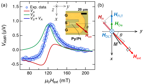
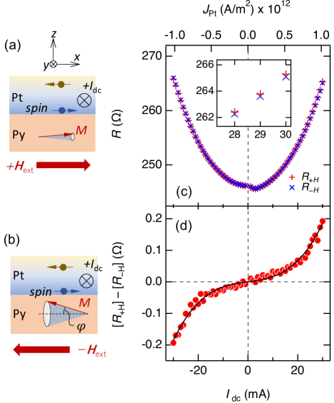
We study metallic bilayers composed of 5 nm thick Pt top layer and 2 nm thick Py bottom layer. The Pt-Py bilayer is deposited after a 3 nm thick tantalum buffer layer on an undoped Si substrate having electrical resistivity at least 1 kcm (Crystal Base, Inc.) Kodama2023 . An inset of Fig. 1(a) shows an optical microscopic image of the specimen consisting of lithographically-prepared Pt-Py strip attached to gold electrodes. The width of the strip is 5 m and the length is 24 m. In ST-FMR measurements, an in-plane external dc magnetic field is applied with a relative angle to the -axis as shown in Figs. 1(a) and 1(b). An ac current with microwave frequencies is applied between the signal (S) and ground (G) lines by a signal generator. The in the Pt layer generates an oscillating Oersted magnetic field, which primarily drives ST-FMR of the Py magnetization . Additionally, the spin-Hall effect in the Pt layer gives rise to ac spin current, which is injected into the Py layer. The spin angular momentum is transferred to the in-plane Py magnetization, exerting a field-like torque (FLT) that secondary drives ST-FMR and a damping-like torque (DLT) that enhances or reduces magnetic relaxation chiba2014prappl ; chiba2015jap ; schreier2015prb . Mixing of and oscillating anisotropic magnetoresistance (AMR) in Py gives rise to a time-independent longitudinal dc voltage . We measure as a function of using a bias tee to obtain ST-FMR signals. All measurements are carried out at room temperature.
III Results
III.1 Spin-torque ferromagnetic resonance measurement
Figure 1(a) shows a typical ST-FMR signal probed by with at 9 GHz. The blue circles correspond to measured . The in a thin film is expressed as , where and are symmetric and anti-symmetric components, respectively Liu2011-vd . Both and are described using , the resonance field (), and the half width at half maximum () of the FMR signal. The fitting in Fig. 1(a) gives = 119.8 mT and = 14.8 mT. The sum of (green line) and (red line) after the fitting is represented by the blue line, which reproduces well the measured .
Together with , a dc current is applied to the bilayer to modify the FMR condition Kasai2014-ia ; Nan2015-yg . The () corresponds to the current in the () direction. The causes a time-independent dc Oersted field along axis as shown in Fig. 1(b). Additionally, generates a time-independent FLT and DLT on . As in Fig. 1(b), FLT and DLT are regarded as effective fields and , respectively. The is spin polarization and is a unit vector of magnetization Fan2013-tq ; Karube2020-df . The and affect the FMR condition, resulting in a shift of and a change in .
To study the shift of and change in by and , the ST-FMR signals with between 20 and 20 mA are measured at various frequency () from 3 to 9 GHz. Thanks to the undoped Si substrate with a better thermal conductivity of 150 W/mK Slack1964-pl compared to quartz (1.4 W/mK) Zhu2018-ib and magnesium oxide (56 W/mK) Stackhouse2010-ph substrates, a large up to 20 mA can be applied (See Supplemental Material SM1 SM ). After the fitting of the ST-FMR signals, we evaluate and at a specific value. The resonance field shift by injection is derived from , where corresponds to at non-zero and corresponds to at zero . Moreover, -dependence of gives Gilbert damping parameter at a specific value.
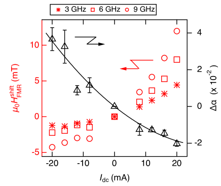
Figure 2 shows versus at = 3 GHz (red asterisks), 6 GHz (red squares), and 9 GHz (red circles) as indicated from the left vertical axis. In addition, the variation in by injection, , reproduced from our previous report Kodama2023 , is plotted as black triangles indicated from the right vertical axis. The and are odd functions of , because is odd function of the dc current. Figure 2 highlights two striking features: i) and are dependent nonlinearly on , and ii) a higher results in a larger at the same . Note that these features are observed in another specimen with a longer Pt-Py strip of 45 m length (see Supplemental Material SM2 SM ).
III.2 Evaluation of variation in effective magnetization
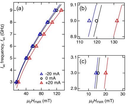
The with various of 20, 0, and 20 mA are plotted as a function of from 3 to 9 GHz in Fig. 3. Blue triangles, black circles, and red triangles correspond respectively to by = 20, 0, and 20 mA. Figures 3(b) and 3(c) show enlarged plots of Fig. 3(a), in which the horizontal axis variations are identical to be 25 mT for direct comparison. At = 3 GHz as in Fig. 3(c), the resonance field shifts upward by 5.7 mT when increases from 20 mA to 20 mA. At a higher of 9 GHz as in Fig. 3(b), the shift amount is larger to be 16.2 mT.
As shown in Fig. 1(b), a component of and parallel to the corresponds to the in-plane effective field . The expressed as , where in the present ST-FMR study, is small, but affects the FMR condition. (see Supplemental Material SM3 SM ). The Kittel equation for FMR is described as
| (1) |
where is gyromagnetic ratio, is resonance field without injection, and is effective magnetization. When = 0 mA, the black circles in Fig. 3 are fitted by Eq. (III.2) with . The fitting gives 658 mT, where is the saturation magnetization. The of 658 mT is smaller than a typical value of Py saturation magnetization, probably due to magnetic dead layers at the Pt-Py interface Kodama2023 ; Hirayama2017-kz .
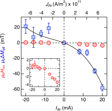
Equation (III.2) is fitted to at 8, 12, 16, and 20 mA to evaluate and . The fitting curves with = 20 and +20 mA are drawn by blue and red solid lines in Fig. 3, respectively. In Fig. 4, evaluated (red circles) and (blue square) are plotted as a function of . The upper horizontal axis indicates the , electrical current density in the Pt layer (see Supplemental Material SM4 SM ). The inset shows an enlarged view of versus . The is very small, slightly decreases with increasing , and reaches at mT when is 20 mA.
Contrastingly, is affected significantly by . The maximum value of at 20 mA is mT, which includes as shown in Fig. 1(b). However, = mT is nonetheless larger than the evaluated from previous reports, for example, mT at approximately 20 mA ( in Refs. Karube2020-df . Note here that with non-zero in Fig. 3 cannot be reproduced using Eq. (III.2) without . This is clearly indicated in Eq. (III.2), i.e., shifts the curves whereas changes the gradient of the curves. The large is indispensable in explaining a larger resonance field shift at a higher . The negative corresponds to shrinkage of , whereas the positive corresponds to expansion. Therefore, we consider shrinkage/expansion of effective magnetization by nonlinear magnon generation/annihilation.
III.3 Unidirectional spin-Hall magnetoresistance measurement
The nonlinear magnon generation/annihilation due to massive spin current injection likely brings about USMR Borisenko2018APL ; Kim2019APEX . We thus conduct USMR measurements with the large injection using the same specimen. Figures 5(a) and 5(b) show schematics of the sample cross section in the - plane viewed to the direction. The is or in the USMR measurements, i.e.,the = mT is applied to the sample in the direction (Fig. 5(a)), while = mT in the direction (Fig. 5(b)). The dc current between 30 mA and 30 mA is chopped to be 0.2 ms width pulses. The longitudinal dc voltage are measured 100 times to obtain an averaged value of .
The measured curve is converted to the dc electric resistance - curve as shown in Fig. 5(c). Red crosses () correspond to under = mT, referred to as , while blue crosses () corresponds to under = mT, referred to as . Because the current is applied beyond the ohmic region, Fig. 5(c) shows a parabolic increase in and due to the Joule heating Chiang2019-ju . Note here that a very similar increase in is confirmed in a measurement using un-chopped continuous as same as in the ST-FMR study (see Supplemental Material SM1 SM ). Figure 5(c) shows that increases from 245 at 0 mA to 255 at 20 mA. Given that a temperature coefficient of Pt resistance is 0.002 , the increase in from 245 to 255 corresponds to the sample temperature elevation of approximately 20 K Belser1959-pc . This evaluation clearly indicates that the Joule heating component is small and not dominant in the present ST-FMR experiments with up to 20 mA.
As highlighted in the inset of Fig. 5(c), an enlarged view at approximately 30 mA, (red crosses) is slightly larger than (blue crosses). The difference between and is plotted as a function of in Fig. 5(d). Note that the small Joule heating contribution, which is independent of the Py magnetization reversal, is already removed in the plot. As increases from 0 mA to 30 mA, increases slowly and then rapidly at above 20 mA. More strikingly, is odd under the direction reversal; this is the hallmark of USMR.
The USMR is caused by the electron scattering by magnons. When the spins are injected into the Py layer, parallel spin injection to the Py magnetization annihilates the magnons as in Fig. 5(a) whereas anti-parallel spin injection generates the magnons as in Fig. 5(b). The magnon generation/annihilation influences the electron-magnon scattering, resulting in a resistance change of the Py layer as USMR. The excited magnon number is increased nonlinearly when the inherent damping of Py is compensated by the anti-damping DLT Borisenko2018APL . This is consistent with nonlinear decrease in observed in Fig. 2. The magnon excitation depending on the current is expressed as , where and are linear and 3rd-order nonlinear coefficients, respectively Borisenko2018APL ; Avci2018 . The fitting gives parameters of , resulting in the ratio as summarized in Table 1. The fitting curve represented by a black solid line in Fig. 5(d) reproduces well the experimental results. This indicates that the USMR in Fig. 5(d) is traced back to the magnon generation/annihilation.
III.4 Magnetization measurement
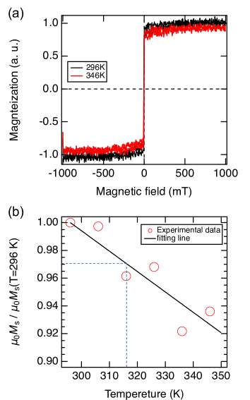
Magnetization of the Pt-Py bilayer are measured using vibrating sample magnetometer (VSM). Figure 6(a) shows magnetization curves at 296 (room temperature, black) and 346 K (red). The magnetization is normalized by the saturation magnetization at 296 K. By elevating the temperature from 296 K to 346 K, decreases slightly. In Fig. 6(b), normalized is plotted as a function of temperature (red circles). decrease monotonically as temperature increases. The solid black line is a linear function obtained by the fitting of red circles. The gradient of the linear function is . When sample temperature is 316 K, corresponding to 20 K elevation from room temperature, the normalized is 0.97.
IV Discussion
The 20 K temperature elevation due to the Joule heating confirmed in the USMR study causes a saturation magnetization decrease by 3 evaluated by magnetization measurements. This value is smaller than the decrease in of 60 mT evaluated in Fig. 4 corresponding to 9 of 658 mT. Moreover, variation is asymmetric for the sign of . Therefore, the Joule heating is not dominant, indicating that the nonlinear spin polarization Xiao2022PRL ; Xiao2023PRL causes the nonlinear spin torque observed in the present ST-FMR study.
The spin polarization is described by an electronic response to an applied electric field as , where , , and are Cartesian indices and the Einstein summation convention is adopted Xiao2022PRL ; Xiao2023PRL . The corresponds to the 2nd-order nonlinear response tensor, which is relevant to the Berry connection polarizability determined by the electronic band structures. In Fig. 2, we focus on the nonlinear variation of because is relevant to the magnitude of spin torque. The nonlinear spin polarization in Pt is partially absorbed by the Py magnetization, resulting in a nonlinear torque (). In this way, the nonlinear torque caused by the nonlinear spin polarization gives rise to depending on . Indeed, the variation of in Fig. 2 is reproduced well by the fitting curve as represented by the black solid lines with . An index of nonlinearity is evaluated to be as shown in Table 1.
Based on the Holstein-Primakoff picture Holstein1940-vb , the magnon number is related to the precession angle as , where is the creation (annihilation) operators for magnons and the is the magnitude squared of the spin angular momentum Nakata2017-ps . Hence, the magnon generation (annihilation), , by the spin injection gives rise to the increase (decrease) of the precession angle , which corresponds to shrinkage (expansion) of the effective magnetization in the -axis direction as in Figs. 5(a) and 5(b) Nakata2017-ps . Because the spin torque is expressed as , the nonlinear magnon generation/annihilation confirmed by the USMR study and followed by the magnetization shrinkage/expansion can thus be another origin of the nonlinear spin torque.
Given that the magnetization shrinkage/expansion contains both the 2nd- and 3rd-order nonlinearity Borisenko2018APL , is expressed as , where , and correspond respectively to the linear coefficient, and the 2nd- and 3rd-order nonlinear coefficients. A fitting curve with represented by a solid black line in Fig. 4 reproduces experimentally obtained values of . The is (, which is similar to ( obtained from USMR measurements. In addition, the is , which is similar to as summarized in Table 1.
| USMR | - | |
|---|---|---|
| ST-FMR magnetization | ||
| ST-FMR damping | - |
The present paper reveals that massive causes the nonlinear spin torque. The nonlinear spin torque has two origins at least. The first origin is electronic one, i.e., the nonlinear spin polarization in the Pt layer. The nonlinear spin polarization results in nonlinear spin torque directly observed by nonlinear variation and represented by and . The second origin is magnonic one, i.e., the nonlinear magnon generation/annihilation confirmed by USMR and effective magnetization shrinkage/expansion, and represented by and . In comparison between and , Table 1 indicates that nonlinear spin polarization is dominant rather than nonlinear magnon generation/annihilation. However, the nonlinear magnon generation/annihilation is caused by the linear spin polarization as well as nonlinear spin polarization Sandweg2011 . Therefore, the magnonic origin could be comparable to the electronic origin. This is a future issue for the theoretical consideration.
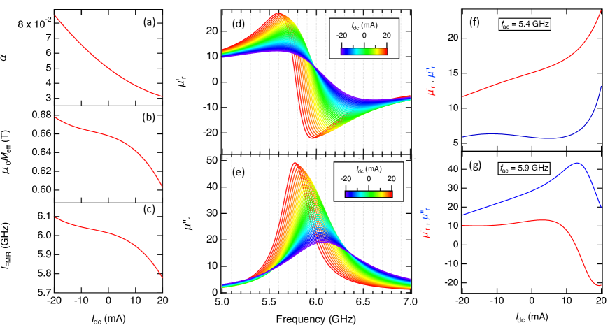
The indices and obtained in ST-FMR and USMR measurements are utilized in nonlinear spintronics of magnetic insulators chiba2014prappl . The nonlinear spin polarization is anticipated to bring about spin-torque oscillation in the Pt-Py bilayer Divinskiy2019 ; Fulara2020-ka . Furthermore, the nonlinear variation of the and due to the nonlinear spin torque enables us to vary significantly the magnetic permeability of the magnetic bilayer system. Figures 7(a) shows nonlinear variation of calculated using . Nonlinear variation of calculated using and is shown in Fig. 7(b). The relationship between and the FMR resonance frequency is expressed by the Kittel equation as
| (2) |
where is the resonance angular frequency. Nonlinear variation of is thus obtained as plotted in Fig. 7(c). Using , and , we evaluate the magnetic permeability variation under a dc external magnetic field mT. The relative permeability is written by real and imaginary parts Kodama2023 as
| (3) |
where
| (4a) | ||||
| (4b) | ||||
By substituting , and into the Eq. (4), at each is evaluated.
Figures 7(d) and 7(e) show dispersion curves of and , respectively, at various from 20 (blue) to 20 mA (red) at 1 mA intervals. In Fig. 7(f), and obtained at 5.4 GHz are plotted as a function of . When is varied from 20 to 10 mA, only the can be modified. Contrastingly, at 5.9 GHz, only can be modified as in Fig. 7(g). This is an advantageous in realizing time-varying permeability metamaterials for the microwave frequency conversion towards 6th-generation mobile communication light source.
V Conclusion
We directly observe the nonlinear spin torque in the Pt-Py bilayer by means of ST-FMR with a large dc current. The nonlinear spin torque observed by nonlinear variation is attributed primarily to nonlinear spin polarization represented by . Moreover, ST-FMR and USMR measurements demonstrate that nonlinear magnon generation/annihilation followed by shrinkage/expansion of effective magnetization, represented by , is another origin of the nonlinear spin torque. Comparison between and indicates that nonlinear spin polarization is dominant rather than nonlinear magnon generation/annihilation. The real and imaginary parts of permeability can be varied independently using nonlinear spin torque. The present paper paves a way to spin-Hall effect based nonlinear spintronic devices as well as time-varying nonlinear magnetic metamaterials with tailor-made permeability.
Acknowledgements
The authors acknowledge Masatoshi Hatayama, Takashi Komine, Saburo Takahashi and Yoshiaki Kanamori for their valuable contributions in this work. N. K., S. O., and S. T. also thank Network Joint Research Center for Materials and Devices (NJRC). This work is financially supported by JST- CREST (JPMJCR2102).
References
- (1) R. W. Boyd, Nonlinear Optics, 3rd ed. (Academic, New York, 2008).
- (2) T. Yamaguchi, N. Akashi, K. Nakajima, S. Tsunegi, H. Kubota, and T. Taniguchi, Synchronization and Chaos in a Spin-Torque Oscillator with a Perpendicularly Magnetized Free Layer, Phys. Rev. B 100, 224422 (2019).
- (3) S. Iwakiri, S. Sugimoto, Y. Niimi, K. Kobayashi, Y. Kozuka, Y. K. Takahashi, and S. Kasai, Generation of Multipeak Spectrum of Spin Torque Oscillator in Non-Linear Regime, Appl. Phys. Lett. 117, 022406 (2020).
- (4) K. Adhikari, S. Sahoo, A. K. Mondal, Y. Otani, and A. Barman, Large Nonlinear Ferromagnetic Resonance Shift and Strong Magnon-Magnon Coupling in Ni80Fe20 Nanocross Array, Phys. Rev. B 101, 054406 (2020).
- (5) T. Hula, K. Schultheiss, F. J. T. Gonçalves, L. Körber, M. Bejarano, M. Copus, L. Flacke, L. Liensberger, A. Buzdakov, A. Kákay, M. Weiler, R. Camley, J. Fassbender, H. Schultheiss, Spin-Wave Frequency Combs, Appl. Phys. Lett. 121, 112404 (2022).
- (6) O. Lee, K. Yamamoto, M. Umeda, C. W. Zollitsch, M. Elyasi, T. Kikkawa, E. Saitoh, G. E. W. Bauer, and H. Kurebayashi, Nonlinear Magnon Polaritons, Phys. Rev. Lett. 130, 046703 (2023).
- (7) K. Hamamoto, M. Ezawa, K. W. Kim, T. Morimoto, and N. Nagaosa, Nonlinear spin current generation in noncentrosymmetric spin-orbit coupled systems, Phys. Rev. B 95, 224430 (2017).
- (8) S. Hayami, M. Yatsushiro, and H. Kusunose, Nonlinear Spin Hall Effect in PT-Symmetric Collinear Magnets, Phys. Rev. B 106, 024405 (2022).
- (9) C. Xiao, H. Liu, W. Wu, H. Wang, Q. Niu, and S. A. Yang, Intrinsic Nonlinear Electric Spin Generation in Centrosymmetric Magnets, Phys. Rev. Lett. 129, 086602 (2022).
- (10) C. Xiao, H. Liu, W. Wu, H. Wang, Y.-X. Huang, X. Feng, H. Liu, G.-Y. Guo, Q. Niu, and S. A. Yang, Time-Reversal-Even Nonlinear Current Induced Spin Polarization, Phys. Rev. Lett. 130, 166302 (2023).
- (11) L. Liu, T. Moriyama, D. C. Ralph, and R. A. Buhrman, Spin-torque ferromagnetic resonance induced by the spin Hall effect, Phys. Rev. Lett. 106, 036601 (2011).
- (12) C. O. Avci, K. Garello, A. Ghosh, M. Gabureac, S. F. Alvarado, and P. Gambardella, Unidirectional spin Hall magnetoresistance in ferromagnet/normal metal bilayers, Nat. Phys. 11, 570 (2015).
- (13) T. Kodama, N. Kikuchi,S. Okamoto, S. Ohno, and S. Tomita, Spin-current Driven Permeability Variation for Time-varying Magnetic Metamaterials, Phys. Rev. Appl. 19, 044080 (2023).
- (14) T. Chiba, G. E. W. Bauer, and Saburo Takahashi, Current-Induced Spin-Torque Resonance of Magnetic Insulators, Phys. Rev. Applied 2, 034003 (2014).
- (15) T. Chiba, M. Schreier, G. E. W. Bauer, and S. Takahashi, Current-induced spin torque resonance of magnetic insulators affected by field-like spin-orbit torques and out-of-plane magnetizations, J. Appl. Phys. 117, 17C715 (2015).
- (16) M. Schreier, T. Chiba, A. Niedermayr, J. Lotze, H. Huebl, S. Geprägs, S. Takahashi, G. E. W. Bauer, R. Gross, and S. T. B. Goennenwein, Current-induced spin torque resonance of a magnetic insulator, Phys. Rev. B 92, 144411 (2015).
- (17) S. Kasai, K. Kondou, H. Sukegawa, S. Mitani, K. Tsukagoshi, and Y. Otani, Modulation of Effective Damping Constant Using Spin Hall Effect, Appl. Phys. Lett. 104, 092408 (2014).
- (18) T. Nan, S. Emori, C. T. Boone, X. Wang, T. M. Oxholm, J. G. Jones, B. M. Howe, G. J. Brown, and N. X. Sun, Comparison of spin-orbit torques and spin pumping across NiFe/Pt and NiFe/Cu/Pt interfaces, Phys. Rev. B 91, 214416 (2015).
- (19) X. Fan, J. Wu, Y. Chen, M. J. Jerry, H. Zhang, and J. Q. Xiao, Observation of the Nonlocal Spin-Orbital Effective Field, Nat. Commun. 4, 1799 (2013).
- (20) S. Karube, N. Tezuka, M. Kohda, and J. Nitta, Anomalous Spin-Orbit Field via the Rashba-Edelstein Effect at the WPt Interface, Phys. Rev. Appl. 13, 024009 (2020).
- (21) G. A. Slack, Thermal Conductivity of Pure and Impure Silicon, Silicon Carbide, and Diamond, J. Appl. Phys. 35, 3460 (1964).
- (22) W. Zhu, G. Zheng, S. Cao, and H. He, Thermal Conductivity of Amorphous SiO2 Thin Film: A Molecular Dynamics Study, Sci. Rep. 8, 10537 (2018).
- (23) S. Stackhouse, L. Stixrude, and B. B. Karki, Thermal Conductivity of Periclase (MgO) from First Principles, Phys. Rev. Lett. 104, 208501 (2010).
- (24) See Supplemental Materials at [http://link.aps.org/supplemental/DOI] for effects of substrate and Pt-Py strip length; evaluation of Oersted field, FLT effective field, and current density, which include Ref. Slack1964-pl ; Zhu2018-ib ; Stackhouse2010-ph ; Nan2015-yg .
- (25) S. Hirayama, S. Kasai, and S. Mitani, Interface perpendicular magnetic anisotropy in ultrathin Ta/NiFe/Pt layered structures, Jpn. J. Appl. Phys. 57, 013001 (2018).
- (26) K.-J. Kim, T. Li, S. Kim, T. Moriyama, T. Koyama, D. Chiba, K.-J. Lee, H.-W. Lee, and T. Ono, Possible contribution of high-energy magnons to unidirectional magnetoresistance in metallic bilayers, Appl. Phys. Express 12, 063001 (2019).
- (27) I. V. Borisenko, V. E. Demidov, S. Urazhdin, A. B. Rinkevich, S. O. Demokritov, Relation between unidirectional spin Hall magnetoresistance and spin current-driven magnon generation, Appl. Phys. Lett. 113, 062403 (2018).
- (28) C. C. Chiang, S. Y. Huang, D. Qu, P. H. Wu, and C. L. Chien, Absence of Evidence of Electrical Switching of the Antiferromagnetic Néel Vector, Phys. Rev. Lett. 123, 227203 (2019).
- (29) R. B. Belser and W. H. Hicklin, Temperature Coefficients of Resistance of Metallic Films in the Temperature Range 25 to 600 ∘C, J. Appl. Phys. 30, 313 (1959).
- (30) C. O. Avci, J. Mendil, G. S. D. Beach, and P. Gambardella, Origins of the Unidirectional Spin Hall Magnetoresistance in Metallic Bilayers, Phys. Rev. Lett. 121, 087207 (2018).
- (31) T. Holstein and H. Primakoff, Field Dependence of the Intrinsic Domain Magnetization of a Ferromagnet, Phys. Rev. 58, 1098 (1940).
- (32) K. Nakata, P. Simon, and D. Loss, Spin Currents and Magnon Dynamics in Insulating Magnets, J. Phys. D Appl. Phys. 50, 114004 (2017).
- (33) C. W. Sandweg, Y. Kajiwara, A. V. Chumak, A. A. Serga, V. I. Vasyuchka, M. B. Jungfleisch, E. Saitoh, and B. Hillebrands, Spin Pumping by Parametrically Excited Exchange Magnons, Phys. Rev. Lett. 106, 216601 (2011).
- (34) B. Divinskiy, S. Urazhdin, S. O. Demokritov, and V. E. Demidov, Controlled Nonlinear Magnetic Damping in Spin-Hall Nano-Devices, Nat. Commun. 10, 1 (2019).
- (35) H. Fulara, M. Zahedinejad, R. Khymyn, M. Dvornik, S. Fukami, S. Kanai, H. Ohno, and J. Åkerman, Giant Voltage-Controlled Modulation of Spin Hall Nano-Oscillator Damping, Nat. Commun. 11, 4006 (2020).