Distances between surfaces in -manifolds
Abstract.
If and are homotopic embedded surfaces in a -manifold then they may be related by a regular homotopy (at the expense of introducing double points) or by a sequence of stabilisations and destabilisations (at the expense of adding genus). This naturally gives rise to two integer-valued notions of distance between the embeddings: the singularity distance and the stabilisation distance . Using techniques similar to those used by Gabai in his proof of the 4-dimensional light-bulb theorem, we prove that .
1. Introduction
Let be a smooth, compact, orientable 4-manifold, possibly with boundary. Let , be connected, oriented, compact, smooth, properly embedded surfaces in . We say that is a stabilisation of if there is an embedded solid tube such that , and is obtained from by removing these two discs and replacing them with , as in Figure 1, and then smoothing corners. In this situation we say that is a destabilisation of .
Definition 1.1.
Given , as above, both of genus , define the stabilisation distance between and to be
where is the set of sequences of connected, oriented, embedded surfaces where , and differs from by one of, i) stabilisation, ii) destabilisation, or iii) ambient isotopy. If no such sequence exists we declare .
Definition 1.2.
Given an immersion , define to be the set of double points. Define the singularity distance to be
where the minimum is taken over all generic regular homotopies from to . If no such regular homotopy exists we declare .
Remark 1.3.
It is possible that and . For example let be the unknot, let , and let be a trivially embedded torus in . Since and are not homotopic .
Further and are related by a destabilisation then a stabilisation, so .
The main theorem of this paper is the following:
Theorem 1.4.
If are connected, smooth, properly embedded, oriented surfaces of the same genus then
The proof is constructive, in that given a regular homotopy with at most double points at each time, we construct a sequence of stabilisations and destabilisations such that the maximum genus occurring is at most . Combining this with the fact that embedded surfaces are regularly homotopic if and only if they are homotopic, see Remark 2.1, we give a new proof of a certain case of Baykur and Sunukjian’s result [BS15, Theorem 1].
Corollary 1.5.
If are homotopic, connected, smooth, properly embedded, oriented surfaces, then they differ by a sequence of stabilisations, destabilisations, and ambient isotopy.
We do not know whether the is really essential. As we discuss in Remark 2, it does not seem obvious how to adapt the proof to prove the inequality without the +1. It would, however, be interesting to find an example where the sequence of stabilisations constructed in the proof is minimal.
Conjecture 1.6.
There exists a smooth, compact, orientable 4-manifold and smooth, properly embedded, orientable, regularly homotopic surfaces and with
Juhász and Zemke define invariants in [JZ18] which bound below the minimum of two similarly defined distances, and using their notation. Their singularity distance is the same as defined here, however , as they allow more general stabilisations and destabilisations. We currently do not know of any invariants that can bound below without also bounding below.
The techniques we use to turn regular homotopies into sequences of stabilisations are inspired by those used by Gabai [Gab17] to prove that if two homotopic embedded surfaces have a common transverse sphere in , where has no 2-torsion, then the surfaces are ambiently isotopic (and so both the distances defined here are ). A transverse sphere for a given embedded sphere is another embedded sphere such that intersects transversely at a single point.
Miller [Mil19] also recently proved, under the assumption that one of the surfaces has a transverse sphere, and that has no 2-torsion, that regularly homotopic surfaces are concordant. There are also modified statements of these theorems when has 2-torsion.
Schwartz found infinitely many examples [Sch18] which demonstrate that the assumption on was essential. She produced 4-manifolds with , and pairs of homotopic embedded 2-spheres in which share a transverse sphere but are not concordant. We would be interested to know the stabilisation and double point distances of these examples.
Schneiderman and Teichner [ST19] recently reproved the 4-dimensional light bulb theorem and characterised the situation for general using an obstruction of Freedman and Quinn.
1.1. The topologically flat case
The condition of smoothness above was required to define regular homotopy. We define regular homotopy in a topological 4-manifold by saying two locally flat surfaces , are regularly homotopic if they differ by a sequence of finger moves, Whitney moves (where the Whitney discs are locally flatly embedded), and ambient isotopy.
We also define stabilisation in the same way, dropping the smoothness condition on the embedding of . Using the topological definitions, we define and analogously. Repeating the proof of Theorem 1.4, without the initial smoothness assumption yields:
Theorem 1.7.
If and are orientable, compact, connected, locally flat, properly embedded surfaces in of the same genus, then,
As a consequence, we prove an analogy of Corollary 1.5 for locally flat surfaces.
Corollary 1.8.
Let and be orientable, compact, connected, locally flat, properly embedded surfaces in . If and are regularly homotopic (topologically), then they differ by a sequence of topological stabilisations, destabilisations, and ambient isotopy.
1.2. Plan of the paper.
The proof of Theorem 1.4 will be set out as follows
-
•
Section 2: We recall standard definitions and results for regular homotopy of surfaces in 4-manifolds. We also define surface tubing diagrams, which are similar to those defined by Gabai [Gab17, Definition 5.5]. These contain the data to replace an immersed surface with an embedded one by removing discs around pairs of intersection points and adding in tubes which run along the surface and join up the resulting boundary circles.
- •
-
•
Section 5: We associate to a regular homotopy a sequence of stabilisations and destabilisations by shadowing, again using the terminology of Gabai [Gab17], the homotopy by a tubed surface as follows.
-
–
At each stage in the regular homotopy where a finger move is performed, we remove the pair of double points by performing a stabilisation which adds a tube running along the surface.
-
–
At each stage in the regular homotopy where a Whitney move is performed, we wish to perform a destabilisation which removes a tube. However, this may not always immediately be possible for several reasons. Firstly, pairs of double points removed by the Whitney move may not have been tubed to each other, but rather to other double points. Secondly, the tubes may not run over one of the arcs of the Whitney circle. Thirdly, the pairing may be ‘crossed’ in the terminology of Gabai [Gab17, ]. We use the results proved in Sections 3 and 4 to change the way that the surface is tubed to eliminate the first two difficulties. We reduce the third difficulty to the fact that two surfaces which are slice surfaces for the unknot, both have the property that they destabilise to the standard disc bounded by the unknot.
-
–
-
•
Section 6: We prove that the pair of slice surfaces and found Section 4 both destabilise to the standard disc bounded by the unknot.
Acknowledgements
Thanks to Andras Juhász for proposing this question, and for the interesting and informative discussion that led me to think about it. Thanks to Stefan Friedl, Maggie Miller, and Matthias Nagel for their interest and helpful comments. Thanks also to Andrew Lobb and Mark Powell for their guidance and for many useful conversations. This research was supported by the EPSRC Grant no. EP/N509462/1 project no. 1918079, awarded through Durham University.
2. Regular homotopy and surface tubing diagrams
We recall some standard definitions, and define surface tubing diagrams, which describe how to turn immersed surfaces of genus with double points, into embedded surfaces of genus .
2.1. Regular homotopy
Recall that embedded surfaces are regularly homotopic if there exists a smooth map (where is an abstract surface), where and are embeddings with , , and is an immersion for all . In the case and have boundary, we require the embeddings be proper embeddings, and that for all .
Remark 2.1.
By theorems of Smale [Sma57] and Hirsch [Hir59] two embeddings of an orientable surface in an orientable 4-manifold are regularly homotopic if and only if they are homotopic. Note that Smale-Hirsch theory gives much more general results about homotopy classes of embedded manifolds. We refer the reader for example to Miller’s treatment in this specific case [Mil19, Theorem 3.3].
We recall the following definitions from [FQ90].
Definition 2.2.
Let be a compact, oriented surface, and a generic self transverse immersion. Suppose are a pair of double points of where the sign of the self intersection at is . Suppose is an embedded disc such that , and the preimage is two disjoint embedded arcs . Note that and , the interiors of the arcs, are disjoint from the preimages of double points of . We call a Whitney disc, and and the Whitney arcs. We require that the canonical framing of restricts on to the Whitney framing of . Here the Whitney framing is determined by a section of which is tangent to along one Whitney arc, and normal to along the other Whitney arc. The Whitney move along is the regular homotopy which moves the sheet containing along to remove the two self intersections; see Figure 2. See [FQ90] for further details.
Definition 2.3.
Let be a compact, oriented surface, and a self transverse immersion. Let be an embedded arc such that , with disjoint from double points of ). The finger move along is the regular homotopy which drags one disc of along to create a pair of intersections in the surface with opposite signs; again see Figure 2.
Remark 2.4.
-
(1)
Two surfaces are regularly homotopic if and only if they differ by a sequence of finger moves and Whitney moves. Moreover, a generic regular homotopy is a sequence of finger moves and Whitney moves. See [FQ90] for a detailed treatment.
-
(2)
Finger moves and Whitney moves are inverse operations; a finger move gives rise to a Whitney disc that undoes the finger move, and a Whitney move gives rise to an arc that undoes the Whitney move via a finger move; again see [FQ90].
Definition 2.5.
Given an arc in the plane , the linking annulus of is the annulus .
Definition 2.6.
Suppose , , and are immersed surfaces in , which intersect each other and themselves transversely only in double points. Suppose that and . Suppose that is an embedded arc in (whose interior is disjoint from and , and from other double points of ). Then tubing along is the result of removing a disc around from , a disc around from , and adding the linking annulus of (parametrising as so that is the plane ), then smoothing corners; see Figure 3.
Remark 2.7.
Usually when we tube, , , and will, in fact, be subsurfaces of the same connected surface in , obtained by taking the intersection of the surface with some ball . Note that the resulting surface, in this case, is oriented if and only if the self-intersections and have opposite sign.
Remark 2.8.
By convention, the middle time picture in movies such as Figure 3 will be referred to as the slice or the present.
2.2. Tubed Surfaces
We shall describe how to replace self transverse immersed surfaces of genus in , with double points, with embedded surfaces of genus by pairing up double points with opposite sign, and tubing along an arc between them. We make the following definition, analogous to that made by Gabai [Gab17, Definition 5.5].
Definition 2.9.
Let be a smooth 4-manifold. A surface tubing diagram , consists of the following data:
-
(i)
A compact, oriented, connected surface possibly with boundary.
-
(ii)
A generic (only isolated double points), self transverse, immersion with and with the same number of positive self-intersections as negative. We take care not to confuse the abstract surface with the immersed surface which is its image, , denoted .
-
(iii)
A partition of the set of double point images, into pairs , with the sign of the intersection being . We denote the preimage of by the pair , which comes with a choice of ordering. We denote the preimage of by the pair . We refer to any pre-images of double points as marked points of the diagram.
-
(iv)
A set of disjoint embedded arcs with endpoints and and which are disjoint from and from (note that their images are also disjoint embedded arcs in ); see Figure 4.
Remark 2.10.
In the topological case we make the same definition for which is an immersion obtained from some locally flat embedding by applying some sequence of finger moves, Whitney moves, and ambient isotopy.
Definition 2.11.
Given a surface tubing diagram we construct the associated tubed surface by tubing to itself along each arc using tubes in a small neighbourhood of each , as in Definition 2.6 with , , , and ; again see Figure 3. Since and have opposite signs the result is an oriented embedded surface which we call .
Remark 2.12.
-
(1)
Ambient isotopy of the immersed surface (which gives rise to an isotopy of the immersion ) describes an ambient isotopy of the arcs , and so by extension an isotopy of the associated tubed surface , where we make sure to keep the tubes close to the surface. At the end of the isotopy, we still have a tubed surface and we still have a surface tubing diagram with the same arcs (but with immersion data , where is the ambient isotopy).
-
(2)
An isotopy of the set of arcs in (which keeps the arcs disjoint from the preimages of self-intersection points throughout the isotopy) gives rise to an isotopy of the tubes and hence of the associated tubed surface.
3. The Tube Swap Lemma
We prove that if we change our surface tubing diagram as depicted in Figure 5, then there is a single stabilisation followed by a single destabilisation taking one associated surface to the other.
The proof is mainly by pictures. We shall draw surfaces in a 4-ball as movies with a time direction, drawing slices of -dimensional space. For the sake of readability, we draw our pictures as piecewise-smooth and so they have corners, however, they should each be understood to describe a smooth surface. The corners arise in two ways, firstly from stabilisations and destabilisations, and secondly when part of the surface ‘jumps’ into the time direction. The reader should mentally smooth these pictures. For stabilisations and destabilisations, the smoothing is as in Figure 1. The corners arising from jumps into the time direction are locally modelled as a product of two arcs which are properly embedded in two discs, one arc having a corner. Smoothing the corner of the arc gives a smoothing of the surface.
Lemma 3.1 (Tube Swap Lemma).
Given a surface tubing diagram , let be any arc in from to which is disjoint from all points and curves in the surface diagram including . Form by removing the arc and replacing it with and changing the order of to and to ; see Figure 5.
Then the associated tubed surface can be transformed into by performing a single stabilisation, followed by a destabilisation and ambient isotopy.
Proof.
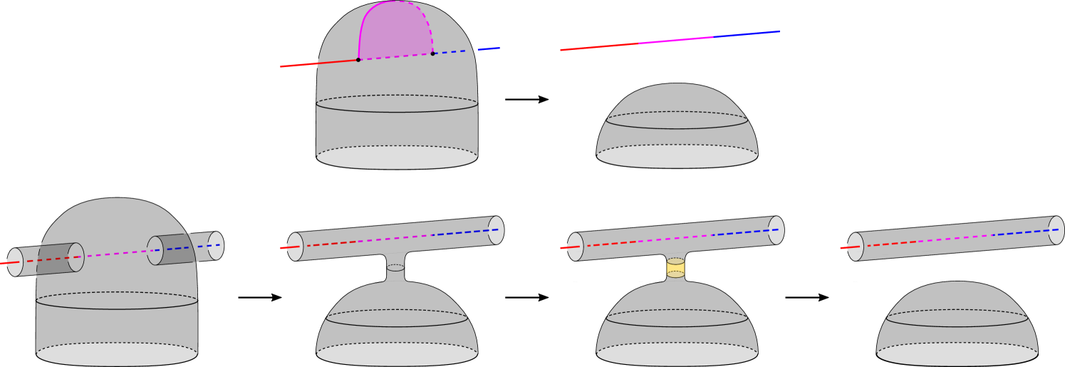
We direct the reader to Figure 6. We first consider a small tubular neighbourhood in , which is diffeomorphic to . We pick a diffeomorphism of to , parametrising so that at we see (the sheet of the immersed surface containing ) and the ends of the arc ). The rest of the sheet containing the ends of extends into the past and future. We extend our parametrisation to one of so that at each we see a copy of , and so is in the frame and the sheet containing it extends into the past and future; see Figure 6.
The associated tubed surface in this parametrisation is depicted in Figure 7.A. We perform a stabilisation between the top of the tube, and the part of surface to obtain Figure 7.B (provided the stabilisation pictured respects orientations; we deal below with the case in which it does not).
To obtain Figure 8.C from Figure 7.B we perform an isotopy supported in the frame by ‘inflating’ the tube from the stabilisation. To obtain Figure 8.D we flatten the resulting bulge, which slightly deforms the surface in other time frames.
Next, we push the sides of the tube into the frame to obtain Figure 9.E. Then we perform an isotopy, flattening the resulting dip to obtain Figure 9.F. To obtain Figure 9.G from Figure 9.F, we thicken the red arc by pushing some of the surface from the future into the present. We then perform an isotopy to create a tube with a band removed, depicted in Figure 9.H.
To obtain Figure 10.I from Figure 9.H we perform an isotopy. In the same picture, we depict an embedded disc intersecting the surface on its boundary in Figure 10.J. We then remove an annulus given by a neighbourhood of the boundary of this disc, and replace it with two parallel copies of the disc in the frame, thus performing a destabilisation, to obtain Figure 10.K. We then push part of the band containing the arc into the future and perform a small further isotopy to obtain Figure 10.L. Note that Figure 10.L is precisely .
In the case that the above stabilisation was not compatible with orientations, we instead perform a stabilisation on the underside of the surface to obtain Figure 11.A. We then perform the sequence of isotopies in Figure 11, which are analogous to those in the previous case. Note that in Figure 11 only the slice is depicted, the past and future pictures are as in the previous case, until the final picture where the past and future images are swapped (i.e. the past images become the future images and vice versa). Figure 11.F is identical to Figure 9.F, except that the past and future images are swapped. We now proceed as above (with the past and future images swapped). Again we obtain , completing the proof of the tube swap lemma. ∎
4. The Tube Move Lemma
We prove that if we take a single arc in our surface tubing diagram, remove it and replace it with another arc, as in Figure 12, there is a single stabilisation and single destabilisation taking one associated surface to the other.
Lemma 4.1 (Tube Move Lemma).
Given a surface tubing diagram , let be an arc in from to which is disjoint from the curves note that may intersect , and is also disjoint from all marked points on the surface other than and . Form by removing the arc and replacing it with .
Then the associated tubed surface can be transformed into by performing a single stabilisation, followed by a destabilisation and ambient isotopy.
Proof.
We direct the reader to Figure 13. In Figure 13.A, we see the associated tubed surface in a neighbourhood of a point which intersects the linking annulus of on a smaller annulus. First, we perform a stabilisation between the tube and the surface to obtain Figure 13.B (note that if this is not compatible with orientations, we instead perform the stabilisation on the underside and proceed in the same way, taking the mirror image of each figure). We then perform an isotopy to obtain Figure 13.C, then push part of the sides of the tube into the present to obtain Figure 13.D. We then perform a further isotopy to obtain Figure 13.E. Here we see two disconnected tubes, whose ends join the surface as depicted in Figure 13.F.
We can now move these ends around freely on the surface, provided during the isotopy they are disjoint from the other tubes and double points. We depict how we drag the ends diagrammatically in Figure 14. First, we retract the two tubes along dragging the ends towards and . We then perform an isotopy that pushes these ends along so that the two tubes now run along and the ends of the tubes lie in a neighbourhood of some point . In this neighbourhood, we see the final picture of Figure 13. We then rejoin the tubes, by performing an isotopy and destabilisation which can be seen by reading the pictures in Figure 13 in reverse order. After rejoining the tubes they form the linking annulus of . The resulting surface is as required. This completes the proof of the tube move lemma. ∎
Remark 4.2.
Note that we cannot prove Lemma 4.1 by using Lemma 3.1 twice, due to the condition in Lemma 3.1 that the new arc is disjoint from the old one. To do so we would need to find an intermediate arc from to disjoint from both and , but if and intersect, then may be disconnected so this may not be possible.
5. Proof of Theorem 1.4
With these tools in place, we proceed with the proof of Theorem 1.4, namely that . We do so by shadowing a regular homotopy by a sequence of embedded surfaces differing by stabilisation, destabilisation, and ambient isotopy.
Proof of Theorem 1.4.
Recall that and are immersed surfaces in of genus . In the case the surfaces are not regularly homotopic and we are done. Hence assume that and are regularly homotopic and suppose . Given distance minimising regular homotopy from to , let be the sequence of immersed surfaces describing this homotopy, each differing from the previous either a finger move, a Whitney move, or an ambient isotopy.
We shall describe a sequence of surface tubing diagrams with associated tubed surfaces that differ by stabilisations, destabilisations, and ambient isotopy, such that the genus of any intermediate surface never exceeds .
Fix the abstract surface , and immersions with image for each . The immersion gives a surface diagram (the empty diagram in ) with associated tubed surface .
We now suppose for induction that we have a surface tubing diagram with immersion data , and associated tubed surface . We will construct a surface tubing diagram with immersion data , such that differs from by a series of stabilisations, destabilisations, and ambient isotopy, such that the genus of any intermediate surface does not exceed . There are three cases; is obtained from by ambient isotopy, a finger move, or a Whitney move.
Ambient Isotopy: If just differs from by ambient isotopy, by Remark 2.12(1) we have a new surface tubing diagram with immersion data . Furthermore, is ambiently isotopic to .
Finger Move: If differs from by a finger move, let and be the Whitney arcs of the Whitney disc that undoes the finger move. Note these arcs are in , the abstract surface. Before we perform the finger move, we perform an isotopy of the arcs, to push any arcs off and to form . We then add the new double points and to the diagram to obtain diagram which we note uses the new map , which differs from by the finger move; see Figure 15. The associated tubed surfaces and are ambiently isotopic by Remark 2.12(2), and and differ by isotopy and a stabilisation, as in Figure 16.
Whitney Move: The Whitney moves present the main difficulty. If differs from by a Whitney move, there are several cases to consider.
The endpoints of the Whitney arcs form the set for some and . In the case that then either and , or and (up to relabeling of and ). We call the former situation Case 1 and the latter situation Case 2. Case 2 is the crossed Whitney disc .
Otherwise, if then either and , or and (again up to relabeling of and ). We call the former situation Case 3 and the latter Case 4.
Note that and may intersect other arcs, including and . In all cases, we perform a small isotopy of all the arcs so that they intersect and transversely.
Case 1: The Whitney arcs are between and , and between and for some . We wish to run in reverse what we did in the case of a finger move, however, we need to run over either or , and we also need and to be disjoint from other arcs, so that the surface tubing diagram looks like the diagram at the end of a finger move, as in Figure 15.
We arrange this by first using the tube move lemma to move any arcs off . To do so we remove intersection points with one by one. We consider the arc which has the intersection with closest to (in the sense of distance along ), at . We form the arc , by removing an arc neighbourhood of from , and replacing it with an arc that runs along the boundary of a small neighbourhood of ; see Figure 17. Provided the neighbourhood is taken to be sufficiently small, is disjoint from and from marked points other than , and so the corresponding associated surfaces differ by a stabilisation and destabilisation by the tube move lemma. We do this for every intersection point of arcs with , until all arcs are disjoint from . Note that we may move during this process.
Next, we use the tube swap lemma to swap to . We then use the tube move lemma to move any arcs off as we did for ; see the third to fourth picture of Figure 17. Finally, we perform the destabilisation and isotopy coming from reading Figure 16 in reverse. This has the effect of removing the points and , and the arc (which now runs along ) from the diagram.
Case 2: The Whitney arcs are between and , and between and for some . This is a crossed Whitney disc. As in Case 1, we first remove any arcs running over and using the tube move lemma, which may move ; see Figure 18. Let be the resulting surface diagram, and be the diagram with the same points and arcs but with the points , the arc deleted, and immersion data ; See Figure 18.
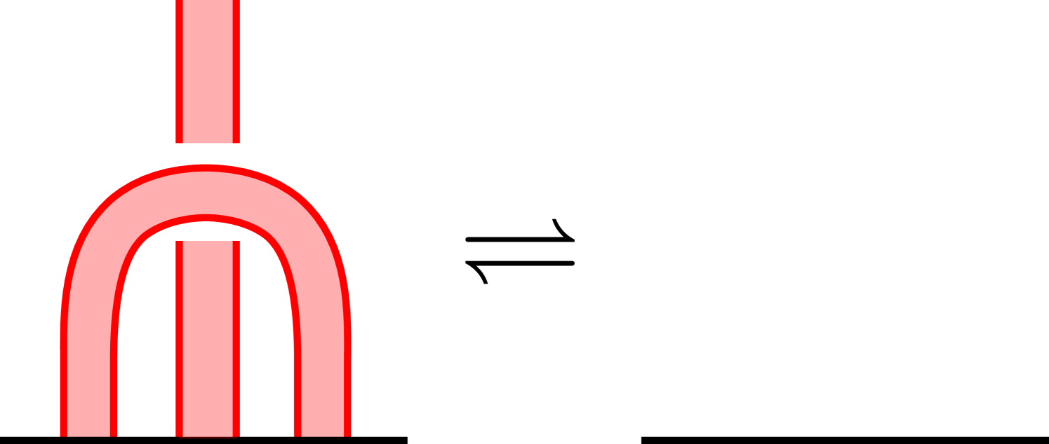
We show and are related by a stabilisation and two destabilisations (and isotopy). We depict the immersed surface in a neighbourhood of the Whitney disc in Figure 20. The associated tubed surface in this neighbourhood is shown in Figure 20. To obtain the second picture of Figure 20 we perform an isotopy which pulls apart the surface (taking the sheets of the surface to where they need to be after the Whitney move), at the expense of creating a double tube again using the terminology of Gabai [Gab17], a Hopf link running through between two disc neighbourhoods of the surface. The Hopf link has four boundary components, two of which are joined to the surface (the top of the green tube and bottom of the pink), while the other two join to the linking annulus of (the bottom of the green and top of the pink).
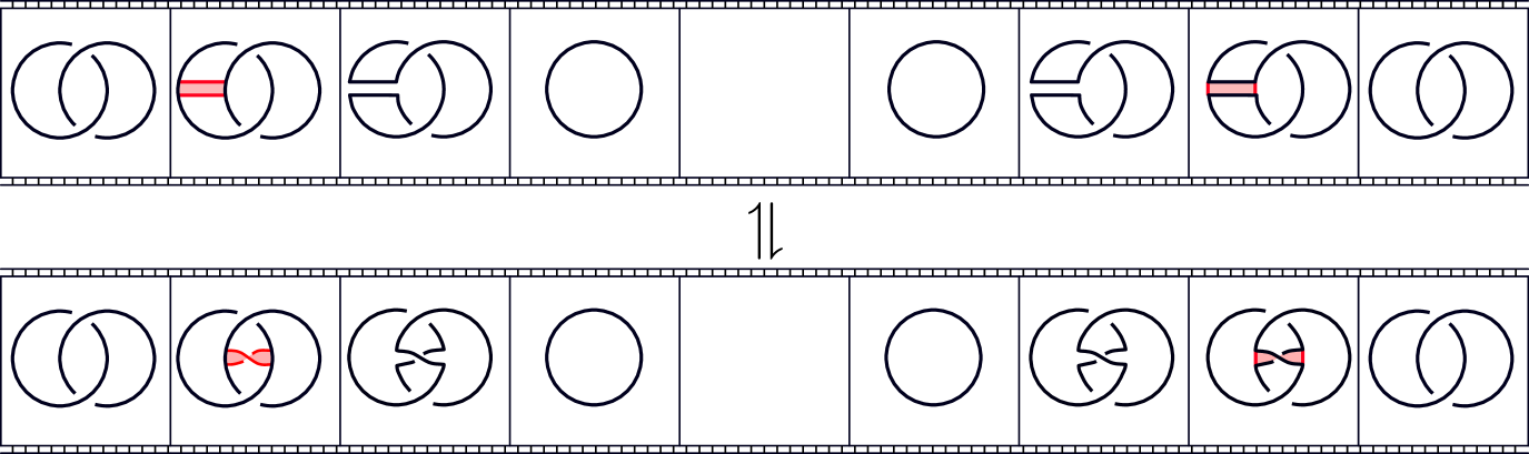
We now perform a stabilisation inside the Hopf link, which can be seen in the movie picture as attaching two bands (provided this is compatible with orientation, if not see below); see Figure 22. The middle picture of this movie is then an unknot, along which we perform a destabilisation to cut the double tube; again see Figure 22.
The resulting ‘end’ of the double tube can be made by taking an open double tube, adding a band between the two tubes, then capping off the resulting boundary circle with a disc. It can also be thought of as the standard annulus whose boundary is the Hopf link whose interior is pushed into the 4-ball. We now suck back these ends to be close to the surface. The resulting surface differs from only in a 4-ball neighbourhood of the arc . The resulting capped off double tube in this 4-ball neighbourhood is pictured on the right in Figure 22. In this neighbourhood, we see a genus 1 slice surface for the unknot. We call this slice surface .
If the above stabilisation was not compatible with the orientation on the double tube, we instead perform a different stabilisation and destabilisation which are compatible with the alternative possible orientations; see Figure 23. Again the result is a cut open double tube, and we again suck the ends back to lie in a 4-ball neighbourhood of . We call the resulting surface in this neighbourhood and note the boundary of is the unknot in as before.
We now wish to construct a sequence of stabilisations and destabilisations taking and to the trivial disc. Such a sequence would remove the mess of tubes, and take our surface to as required. We exhibit such a sequence in Lemma 6.2. Note that results in [BS15] imply that some sequence of stabilisations and destabilisations exists but we show that in fact, one destabilisation is sufficient, and so the genus of any intermediate surface does not exceed .
Case 3: The Whitney arcs consist of an arc between and , and an arc between and for . This case presents the most diagrammatic difficulty. We wish to remove the intersections of arcs with and , however this is made difficult by the fact that and may intersect and in a complicated way; see Figure 24.
To overcome this, we first we pick an arc from to which is disjoint from and all other marked points on the surface; clearly, we may do so since the complement of and all points is connected. We then similarly pick an arc from to which is disjoint from and all marked points other than and ; again the complement of these arcs and points is connected since does not intersect or . We remove the intersections of all arcs with , which is one long embedded arc, one by one using the tube move lemma as in previous cases; see Figure 24. Note that this may move and .
We now use the tube swap lemma to swap to and to . We then move any arcs off using the tube move lemma.
Finally we remove the intersection points , , , , join the arcs and using , and change the index of the points labelled to ; see Figure 24. The corresponding isotopy and destabilisation of the associated surface is given by Figure 25.
Case 4: The Whitney arcs are an arc between and , and an arc between and for . In this case, we use the tube swap lemma to swap to any arc between and disjoint from other tube arcs, but which may intersect and ; some such arc exists since the complement of is a punctured surface, so is connected. We are then in Case 3 and proceed as before.
Examining the proof, we in fact prove a stronger, if more technical, fact.
Proposition 5.1.
Let and be immersed surfaces with , both with the same number of positive and negative double points. Suppose they are regularly homotopic through surfaces with at most double points. Then given a surface tubing diagram for , there exists a surface tubing diagram for such that
Note that taking both and to be embeddings yields Theorem 1.4, since the only surface tubing diagrams for embeddings are the empty diagram.
Remark 5.2.
-
(1)
Schwartz [Sch18] constructs pairs of embedded spheres in a 4-manifold with 2-torsion in , which are regularly homotopic, and are such that any regular homotopy between them must contain a crossed Whitney move.
-
(2)
For each finger move we made a choice of Whitney arc to tube along; we tubed along , but we could equally have tubed along . In the absence of a crossed disc we may make this choice so that only Case 1 and Case 3 Whitney moves occur. Indeed considering a homotopy as a map , the set of double points is a union of circles. Each double point circle has two disjoint circles as its preimage, . Labelling the double point preimages so that and gives such a choice of tubing.
6. Destabilising the Slice Surfaces and
We complete the proof of Theorem 1.4 by showing that both and become the standard disc bounded by an unknot in after a single destabilisation.
6.1. Banded link presentations of knotted surfaces
First, we review the calculus of banded link presentations for slice discs and 2-knots set out by Jablonowski [Jab16].
Definition 6.1.
A banded link presentation of a smooth embedded surface bounded by a link in , consists of the link , where denotes the unlink with components, along with a number of bands, embedded copies disjoint from each other and , except at the ends of the bands which lie in . Performing a band move is the operation of removing the ends of the bands from and adding in the sides of the bands . We require that the resulting link after performing all the band moves to is the unlink.
A banded link presentation describes a slice surface for via a movie which can be seen by considering as . The first slide in this movie is . In the next, we add the unknotted components of , these correspond to minima of the surface with respect to the projection onto . In the next slide we a perform a band move on each band, which corresponds to adding saddles to the surface. After performing these band moves we obtain the unlink for some . Each component of this unlink is then capped off with a disc, corresponding to maxima of the surface.
There are several moves on banded link diagrams one may perform that give isotopic surfaces. These are isotopy of the diagram, band slides, band swims, cancelling a maximum with a saddle, and cancelling a minimum with a saddle; see Figure 26.
Stabilisation or destabilisation in banded link diagrams corresponds to adding or removing respectively two bands, as in Figure 27. Note that it does not matter where the loose end of the band goes.
6.2. Proof that and destabilise to the standard disc
Lemma 6.2.
The surfaces and , described in Case 2 in the proof of Theorem 1.4, become the standard disc bounded by the unknot in after a single destabilisation.
Proof.
We first consider Figure 22. We recall that the ‘capped-off’ ends are made by attaching a band between the tubes and capping off by a disc as in Figures 22 and 23. After an isotopy, the -direction as depicted in Figure 28 gives the standard Morse function for , which restricts to a Morse function on the surface. With this Morse function the surface has one minimum and two saddles, then two further saddles and two maxima from the caps.
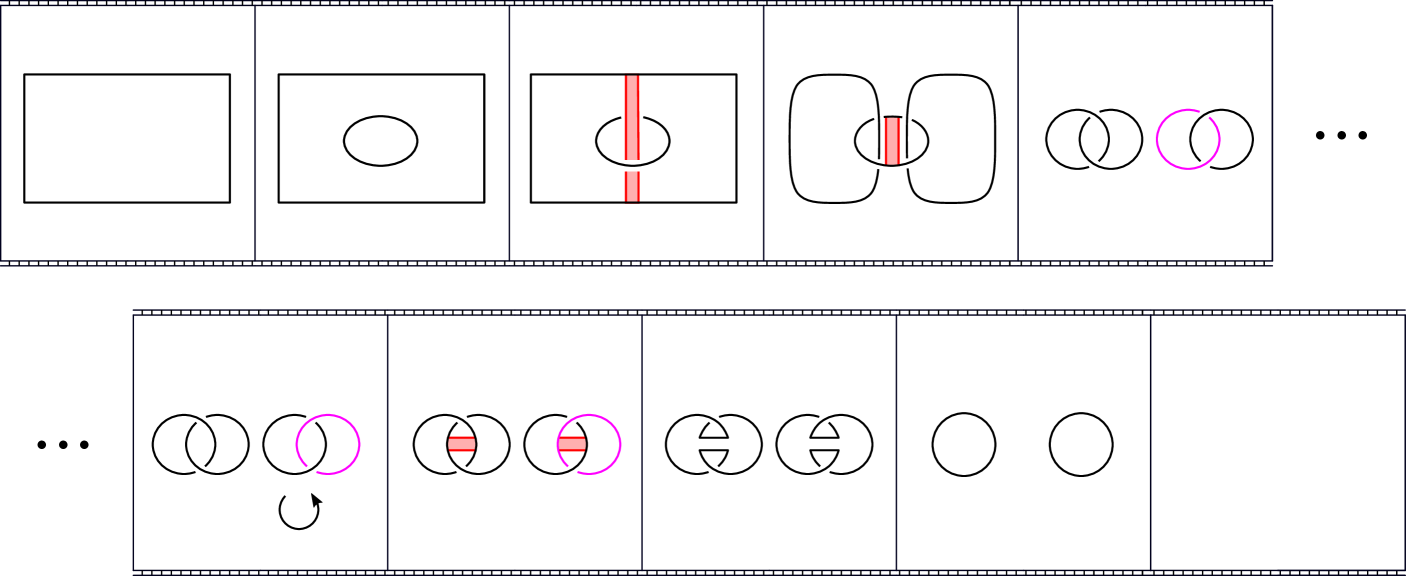
This Morse function gives a movie presentation for the surface in the 4-ball; see Figure 30. We deform this into a band presentation, depicted in Figure 30, which we simplify using band swims, slides, and a destabilisation, to obtain the standard disc.
In the case of , recall that we stabilised the outside of one tube with the inside of the other, which has the effect of adding a half twist to the bands; see Figure 31. After a band swim and isotopy, we obtain the mirror image of Figure 30 and proceed as before (taking the mirror image of each picture), destabilising to obtain the standard disc. ∎
References
- [BS15] R. I. Baykur and N. Sunukjian, Knotted surfaces in 4-manifolds and stabilizations, J. Topol. 9, no. 1 (2015), 215–231
- [FQ90] M. H. Freedman and F. Quinn, Topology of 4-Manifolds (PMS-39), Princeton Univ. Press (1990)
- [Gab17] D. Gabai, The 4-Dimensional Light Bulb Theorem, J. Amer. Math. Soc (To appear) (2017)
- [Hir59] M. W. Hirsch, Immersions of manifolds, Trans. Amer. Math. Soc. 93, No. 2 (1959), 242-276.
- [Jab16] M. Jablonowski, On a banded link presentation of knotted surfaces, J. Knot Theory Ramifications 25, No. 3 (2016)
- [JZ18] A. Juhász and I. Zemke, Stabilization distance bounds from link Floer homology, Preprint (2018) arXiv:1810.09158v1
- [Mil19] M. Miller, A concordance analogue of the 4-dimensional light bulb theorem, Int. Math. Res. Not. IMRN, (to appear) (2019)
- [ST19] R. Schneiderman and P. Teichner, Homotopy versus isotopy: spheres with duals in 4-manifolds, Preprint (2019) arXiv:1904.12350
- [Sch18] H. R. Schwartz, Equivalent non-isotopic spheres in 4-manifolds, J. Topol., 12: 1396-1412. (2019)
- [Sma57] S. Smale, A classification of immersions of the two-sphere, Trans. Amer. Math. Soc. 90, No. 2 (1957), 281–-290.