com short = CoM, long = Center of Mass, first-style = short-long, \DeclareAcronymcog short = CoG, long = Center of Geometry, first-style = short-long, \DeclareAcronymwrt short = w.r.t., long = with respect to, first-style = short-long, \DeclareAcronymee short = EE, long = End-Effector, first-style = short-long, \DeclareAcronymdof short = DoF, long = Degree of Freedom, first-style = short-long,
Dynamic Center-of-Mass Displacement in Aerial Manipulation: An Innovative Platform Design
Abstract
Aerial manipulators are increasingly used in contact-based industrial applications, where tasks like drilling and pushing require platforms to exert significant forces in multiple directions. To enhance force generation capabilities, various approaches, such as thrust vectoring and perching, have been explored. In this article, we introduce a novel approach by investigating the impact of varied \accom locations on an aerial manipulation system’s force exertion. Our proposed platform features a design with a dynamically displacing \accom, enabling a smooth transition between free flight and high-force interactions supported by tilting back rotors. We provide detailed modeling and control strategies for this design and validate its feasibility through a series of physical experiments. In a pushing task, the proposed system, weighing , was able to stably exert over of force on a work surface—nearly equivalent to its gravitational force—achieved solely through the tilting of its back rotors. Additionally, we introduce a new factor to evaluate the force generation capabilities of aerial platforms, allowing for a quantitative comparison with state-of-the-art systems, which demonstrates the advantages of our proposed approach.
I Introduction
Critical working conditions in industrial applications, such as oxygen-deficient environments, operations at heights, and offshore tasks, often pose challenges related to workspace safety, labor shortages, and high costs [1]. Recently, the utilization of aerial manipulators for such operations has become increasingly established [5, 2]. These platforms have demonstrated effectiveness in contact-based inspections through pushing [6, 8, 27, 11, 20, 18, 19] and in maintenance operations like drilling and grinding [3, 4, 12, 16]. Such tasks demand the aerial platform to exert significant forces in various directions.
The development of aerial manipulators, especially multirotors, capable of physically interacting with the environment has experienced significant growth over the past decade [2, 5]. Traditional uni-directional thrust [5] multirotors (e.g., quadrotors, hexacopters, octocopters) are energy-efficient but are limited by the inherent coupling between linear and angular dynamics, which restricts their force generation capability in both magnitude and direction during interactions [17, 18].
To address this, higher-\acdof manipulators have been mounted on uni-directional thrust multirotors, as seen in [6, 7, 17, 18]. However, these platforms still face limitations in force magnitude due to the coupling between gravity compensation and horizontal force generation during physical interactions [18]. An alternative is thrust vectoring, achieved either by fixed tilted rotors [8, 9, 10], or tiltable rotors [29, 11, 12, 13, 27]. In [29, 8, 9, 10, 11, 27, 13], authors present aerial vehicles achieving 6-\acdof wrench generation in the space being fully-actuated. These platforms often suffer from counteracting unwanted thrust components, high energy consumption, and control complexity due to extra actuation compared to uni-directional thrust multirotors. Moreover, full actuation is not always necessary for tasks like pushing and drilling on non-horizontal surfaces.
Some solutions, such as the H-shaped aerial vehicles [12, 13], use 5-\acdof actuation by tilting both front and back rotors. While this design is effective, similar tasks can be performed by tilting only one side of the rotors (front or back), reducing the complexity of actuation, see Fig. 2(a). This minimalist rotor configuration, however, raises challenges when significant forces need to be exerted on the environment.
Existing approaches to increase the force generation of aerial platforms typically involve increasing thrust capacity through larger propellers, co-axial designs [27], perching [3], or adding mechanical compliance [6]. Additionally, most current designs feature a fixed \accom within the rotor-defined area. In [15], a moving battery was used to compensate for the gravitational effects of a heavy manipulation arm. However, there remains a gap in the literature concerning the effect of various \accom locations on force generation during physical interactions.
In this work, we address this gap by proposing a novel aerial manipulation platform that leverages dynamic \accom displacement to enhance force generation during physical interactions. In contrast to [30], we provide a comprehensive analysis of the platform’s force generation as influenced by varied \accom locations. We detail the system’s design, modeling, and control and validate the proposed concepts through physical experiments involving both free-flight and pushing tasks. Additionally, we introduce a quantitative factor to compare the force exertion capabilities of our system with existing platforms, highlighting the advantages of our approach.
II Design Motivation
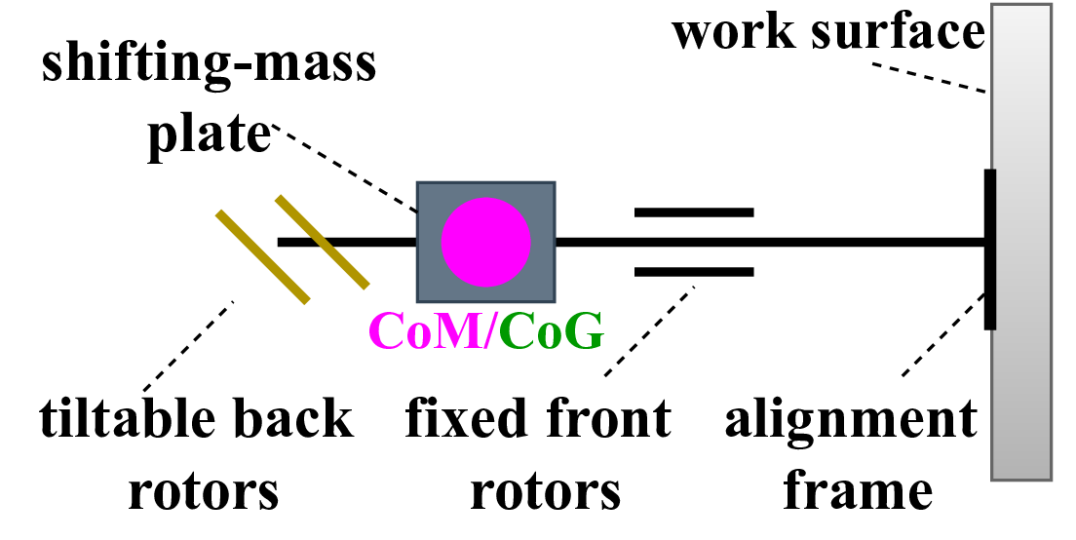
In this section, we explore how varying the \accom location affects force exertion in aerial manipulation, which motivates the design of our proposed aerial system. Specifically, we analyze the performance of an H-shaped aerial system equipped with tilting back rotors and fixed front rotors, as illustrated in Fig. 2(a). This system features a rigid link attached to the vehicle body for interacting with a vertical work surface during a pushing task. Our analysis focuses on how the \accom’s position influences the system’s ability to exert forces effectively on the work surface.
II-A Wrench Analysis
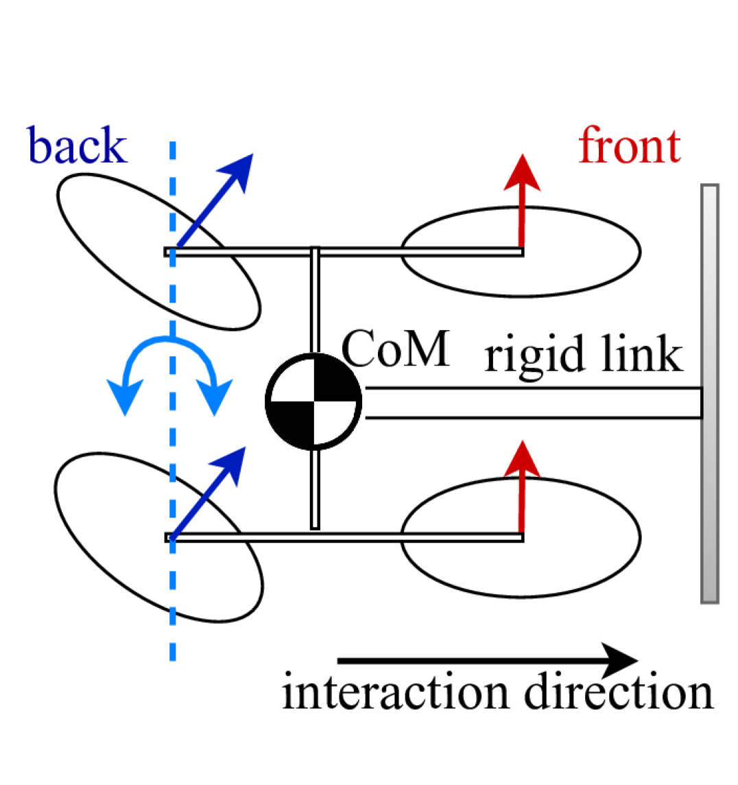
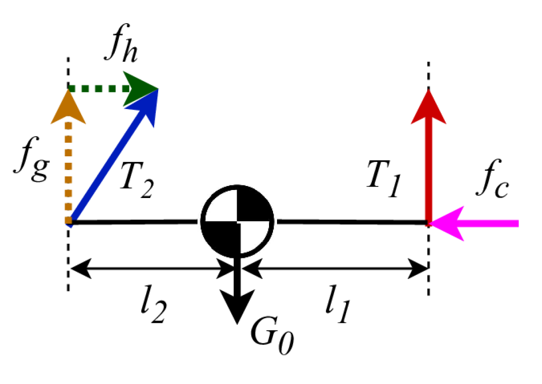
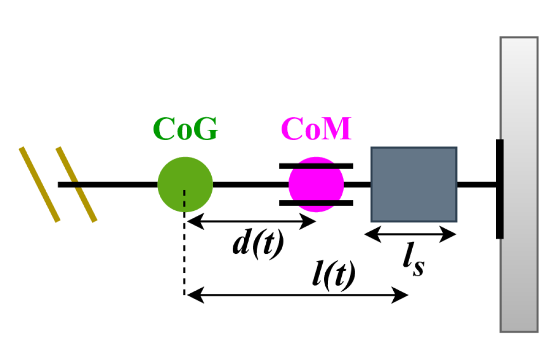
We assume that the aerial vehicle is symmetric around the main axis of the rigid link along the interaction direction as in Fig. 2(a). By neglecting small friction forces, the problem simplifies to a planar scenario, as illustrated in the free body diagram in Fig. 2(b). We denote and as the thrust magnitude of the front and back rotors, respectively, and as the gravitational force acting on the total system. The component of along the interaction direction is , while represents the component of opposing the gravitational force. The contact force exerted by the environment, passing through the system’s \accom, is denoted by . We define and as the distances between the propellers’ centers and the \accom. Assuming the system is in equilibrium during interaction, with zero net forces and torques, the following relationships hold:
| (1) | ||||
| (2) | ||||
| (3) |
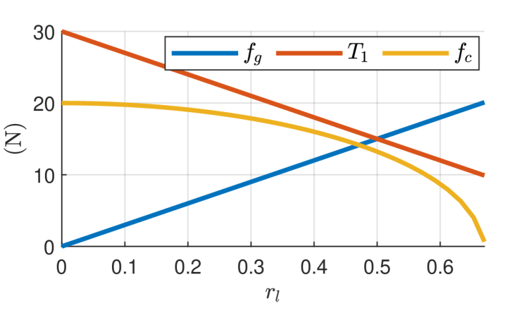
where . The distance between front and back rotors is fixed. To investigate the effect of \accom location on the system’s force exertion, we analyze the case with , , and . By varying within its feasible range, the forces change according to eqs. 1, 2 and 3, as depicted in Fig. 3.
In traditional aerial system designs with a fixed \accom, the configuration typically corresponds to . In this setup, the thrust from the back rotor generates a component that partially compensates for the gravitational effect, in conjunction with the thrust from the front rotor . Consequently, the force applied to the environment is limited to of the back rotor thrust . When the \accom is shifted closer to the back rotor (), the force exerted on the environment decreases. As illustrated in Fig. 3, approaches zero as increases beyond , reaching near zero around . This demonstrates that moving the \accom closer to the back rotor reduces the system’s overall force exertion capability.
Conversely, moving the \accom closer to the front rotors () enhances force generation on the work surface. When , the system exerts the maximum force on the environment, with . In this configuration, the back rotor thrust is fully utilized to generate the contact force on the work surface, while the gravitational component is zero. The system’s \accom is aligned with the front rotors at and the front rotor thrust fully compensates for the gravitational force, resulting in .
II-B Proposed Design Concept
The wrench analysis indicates a novel approach to enhance force generation in aerial systems: shifting the system’s \accom closer to the front rotors. Traditional underactuated aerial vehicles with 4-\acdof are known for their energy efficiency, particularly when carrying heavy loads or manipulators. Therefore, we propose a novel aerial system design that functions as a 4-\acdof vehicle during navigation (in navigation mode), with a fixed \accom aligned with the \accog.
For interaction tasks (in interaction mode), the platform features tiltable back rotors and a dynamic \accom displacing configuration. This configuration allows the platform to adjust its \accom position closer to the front rotors during interactions, thereby enabling higher force exertion.
In the following sections, we detail the design, modeling, and control of this aerial manipulation system, specifically addressing the dynamic \accom design.
III System Design
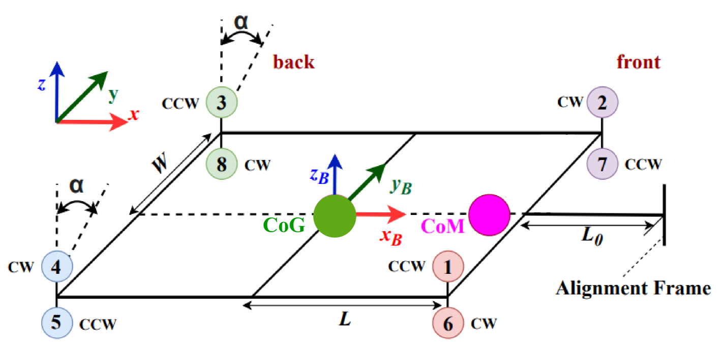
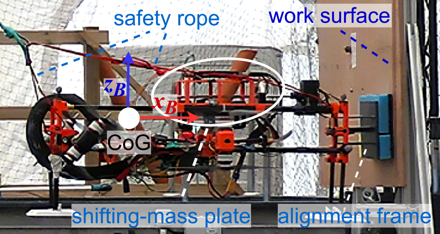
In this section, we detail the system design of the aerial vehicle adapting the design concept introduced in the previous section. The aerial vehicle’s rotor configuration follows the design of an H-shaped coaxial octocopter with the body frame attached to its \accog, as in Fig. 4. Rotors , , , and in the front have fixed rotating axes parallel to . Rotors , , , and on the back have parallel tiltable axes that can simultaneously tilt around via a servo motor. We denote as the tilting angle between each tiltable axis and . Such design introduces an additional \acdof to the system compared to the classic coaxial octocopters with -\acdof actuation by entailing the decoupling between horizontal force generation along and gravity force compensation of the platform. This feature enables interactions with non-horizontal surfaces at different orientations using a rigidly attached link, referred to as the alignment frame, see Fig. 1.
The aerial vehicle also features a dynamic \accom that can be displaced along the body axis . This displacement is achieved by moving a shifting-mass plate, which includes heavy components such as the battery, manipulator, and tools, using a linear actuator. Positioning the shifting-mass plate at the aerial vehicle’s \accog ensures that the system’s initial \accom coincides with the \accog. Positioning the shifting-mass plate at the aerial vehicle’s \accog allows us to assume that the system’s initial \accom coincides with the \accog. The distance between the system \accog and each rotor center along is represented by , while the distance along is denoted as . represents the length of the alignment frame.
As outlined in Sec. II-B, different operation modes are assigned to the aerial vehicle including the navigation mode and the interaction mode for pushing tasks. In navigation mode, the vehicle functions as a classic coaxial octocopter with a fixed \accom. Upon switching to interaction mode, the tiltable back rotors and the dynamic \accom become active. The platform establishes initial contact with the work surface using the alignment frame, with the \accom positioned as shown in Fig. 5(a). While maintaining this contact, the shifting-mass plate moves closer to the work surface, thereby bringing the \accom nearer to the front rotors, as illustrated in Fig. 5(b). As the \accom shifts closer to the front rotors (with a reduced ), more thrust from the back rotors can be utilized to generate a higher pushing force as depicted in Fig. 3.
III-A Dynamic Center-of-Mass Displacing
We denote as the mass of the shifting-mass plate and the total system respectively, where . The shifting-mass plate is connected to a linear actuator and can move along starting from the system’s \accog up to the alignment frame tip. The location of the shifting-mass plate is represented by its \accog position. We denote as the length of the shifting-mass plate along the body axis , as in Fig. 5(b). The shifting-mass plate position along \acwrt the body frame origin is denoted as . Changing the shifting-mass plate position results in a displacement of the system’s \accom along , denoted by . When the system’s \accom is located at outside the rotor-defined area (i.e., over-displaced), the aerial vehicle often flips around the contact area, leading to instability. Therefore, is restricted by to avoid risky scenarios and damage to the platform. Assuming the symmetric mass distribution of the platform around its body axes, the relation between and is given by:
| (4) |
With eq. 4,the maximum \accom displacement corresponding to the case in Fig. 3 results in a shifting-mass plate position of . The shifting-mass plate position is thus restricted to . Neglecting friction forces from the work surface, with , only front rotors supply the force for gravity compensation. The back rotors can tilt up to to be fully used for generating the pushing force.
III-B Physical Prototype
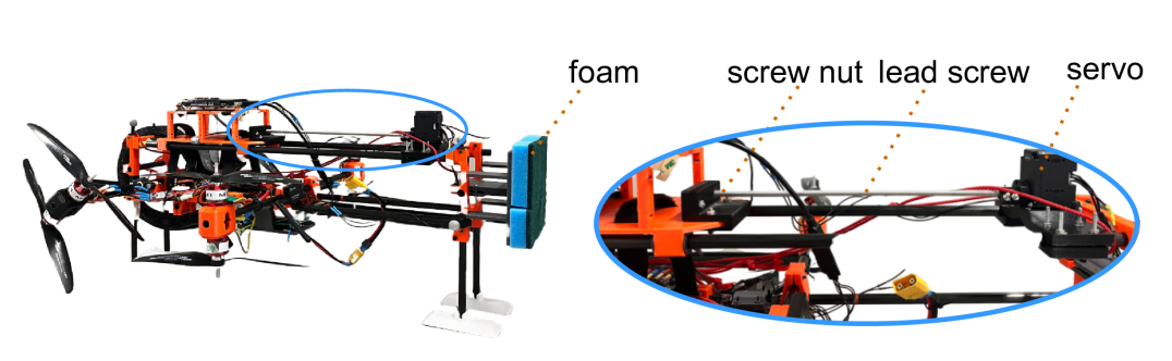
A physical prototype with a total weight of has been developed from scratch, utilizing 3D-printed parts and carbon-fiber tubes. This prototype facilitates simple pushing tasks using the alignment frame, as shown in Fig. 5(c). The linear motion of the shifting-mass plate is enabled by a lead screw, a Dynamixel servo, and a screw nut housed in a box rigidly attached to the shifting-mass plate, for details please refer to [30]. This design ensures precise, slow motion of the plate, with a velocity of , making the dynamics of shifting the \accom negligible. To enhance the interaction quality, foam is attached to the tip of the alignment frame, providing mechanical compliance to reduce impact during initial contact and ensuring smooth interaction.
IV System Modeling
In this section, we present the system modeling of the designed aerial vehicle in Sec. III. Concerning Fig. 4, we define as the world frame. The thrust magnitude of the -th rotor is denoted by , where is the thrust coefficient and is the rotor rotating speed. According to the rotor configuration in Fig. 4, the drag torque of the -th rotor along the positive thrust direction is given by , where is the drag torque coefficient. The rotation matrix represents the orientation of the body frame w.r.t. the world frame where , , are roll-pitch-yaw Euler angles.
IV-A Moment of Inertia Estimation
To simplify the modeling, we assume that the body axes of frame correspond with the system’s principal axes of inertia. Unlike the conventional aerial vehicles with fixed centers of mass and constant moments of inertia, while displacing the system’s \accom along the body axis , the moments of inertia along body axes and vary.
To reduce modeling inaccuracies, we present the moment of inertia estimation associated with the shifting-mass plate position . To do so, the geometry, mass, and moments of inertia of the main components used in the physical model in Fig. 1 are captured by realistic CAD models. By measuring, stays constant for different value of , while and change values along with . With the measured data and similarly to [33], linear regression technology is applied to obtain mathematical models of and \acwrt :
| (5) |
The estimated inertia matrix of the designed system is thus given by .
IV-B System Actuation
We now introduce the actuation wrenches (i.e., forces and torques) of the system in Fig. 4. Given the tiltable back rotors, the aerial vehicle can have thrust components along the interaction axis . The actuation force vector expressed in the body frame is given by111For simplicity, and denote and , while represents the sum of thrust and drag torques, e.g., :
| (6) |
The actuation torque vector \acwrt the system’s \accom expressed in is given by:
| (7) |
The system therefore has 5-\acdof actuation provided by 9 system inputs including the rotors’ rotating speed and back rotors’ tilting angle. We denote as the system inputs.
IV-C Equations of Motion
Assuming slow motion of the shifting-mass plate, we neglect the dynamics of the moving plate. The system equations of motion expressed in the body frame can be written as:
| (8) |
where is the mass matrix. is the gravity term expressed in the body frame. Considering the \accom displacing, we have:
| (9) |
with , , and from eq. 4. are the linear and angular velocity vectors of the body frame \acwrt the world frame. Assuming that the interaction wrenches at the end-effector and alignment frame tip are the only sources of external wrenches, we denote as the stacked force and torque vector exerted from the environment to the system. We use to present the skew symmetric matrix such that , and we have . We define the operator such that .
V Control Design
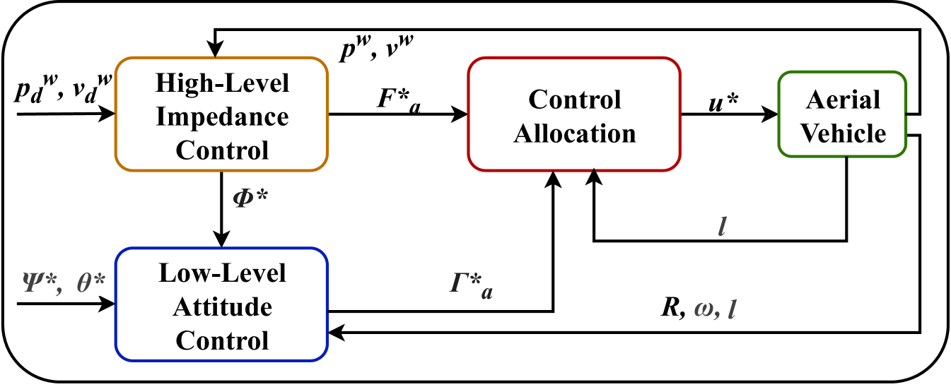
In this section, we present the control design of the aerial vehicle for the interaction mode with a dynamic \accom displacing configuration. Considering the modeled system’s under-actuation and inspired by [12, 27, 28], we employ a cascade control pipeline as summarized in Fig. 6 with the capability to handle both free flights and physical interactions. In the following, indicate the desired quantities. This control framework integrates low-level geometric attitude control and high-level selective impedance control outputting the desired actuation wrenches , . These outputs are sent to the control allocation to compute the desired rotors’ rotating speed and tilting angle .
V-A Low-level Geometric Attitude Control
We use the geometric controller in [28] to control the system’s attitude dynamics. The low-level controller outputs the desired actuation torques by tracking the system’s orientation and angular velocity in the body frame. The attitude tracking error is defined as and the angular velocity tracking error is defined as: . We define the integral error , with being a positive constant. A nonlinear attitude dynamics feedback controller is designed as the following:
| (10) |
where , , and are positive-definite matrices.
V-B High-level Selective Impedance Control
The high-level selective impedance control outputs the desired actuation forces by tracking the body frame origin attached to the aerial vehicle’s \accog, instead of the shifting-mass plate in the world frame. The system’s linear dynamics can be re-written as:
| (11) |
where and . Considering the frame transformation and eq. 6, is given by:
| (12) |
The position tracking error is given by , where represents the position of the origin \acwrt expressed in the world frame. The velocity tracking error can then be displayed as with . The desired close loop dynamics of the system with the selective impedance control is:
| (13) |
where and are positive-definite matrices representing the desired damping and stiffness of the system. Combining eq. 11 and eq. 13, the desired actuation force vector expressed in the world frame is defined as:
| (14) |
The system introduces coupling between its roll angle and its linear motion in the world frame not having a thrust component along the body axis . Again, combining eq. 12 and eq. 14 the desired roll angle is calculated via:
| (15) |
Furthermore, by using trigonometric calculations with eq. 12, the desired actuation force vector expressed in the body frame is given by:
| (16a) | |||
| (16b) |
The desired roll angle is then fed to the low-level attitude controller in Sec. V-A with the attitude references and . Finally, and are fed to the control allocation to derive the desired system inputs , as in Fig. 6.
V-C Control Allocation
The control allocation problem for the examined case can be divided into finding the desired tilting angle value,
| (17) |
and retrieve the corresponding motor velocities . To handle the redundancy of the system, we introduce a virtual control input vector . By applying eq. 4, eq. 6, and eq. 7 the desired virtual control vector is calculated via pseudo-inverse:
| (18) |
where is the allocation matrix depending on the desired tilting angle and is the associate pseudo-inverse operator. Finally, we can compute the desired real system inputs as . This approach minimizes the motors’ rotating speed with guaranteed positive values [29].
VI experimental results
In this section, we present the experimental results obtained from the built system, including both free-flight tests and two interaction task scenarios. The platform’s navigation mode is managed by the standard PX4 firmware [31], while the interaction mode is tested with a customized controller, as shown in Fig. 6. Free-flight tests were conducted to validate the performance of the proposed cascade controller described in Sec. V. In Scenario 1 and Scenario 2, we performed pushing tasks on a vertical surface with the platform both with and without dynamically displacing the \accom. These scenarios are designed to demonstrate the advantages of the proposed system’s dynamic \accom configuration. Additionally, we introduce a quantitative factor to compare the force exertion capabilities of our system with those of existing platforms.
VI-A Experiment Setup
The entire control architecture is implemented via a customized PX4 firmware [32] enabling the support for the servo motor to tilt back rotors and a ROS2 controller (in C++) implementing the designed control law. A separate ROS2 controller is used to move the shifting-mass plate, in which the shifting-mass plate position is mapped into the servo position. The C++ control node operates at Hz matching the standard PX4 controller frequency. The following gain values are used during the experiments: , , , , , and . The codes run on an onboard Lattepanda Delta V3 which communicates with the flight controller via DDS and ROS2. An OptiTrack system is used to track the platform’s position and orientation. A vertical wooden board is set as the work surface, and safety ropes are used to prevent platform damage, see Fig. 1. In practice, the mass distribution across the platform is not symmetric around the body axes. Directly moving the shifting-mass plate to as introduced in Sec. III-A may lead to over-displaced \accom resulting in risky situations for the platform. Therefore, to avoid platform damage due to over-displaced \accom, we tested a maximum shifting-mass plate position of .
VI-B Free-Flight Tests
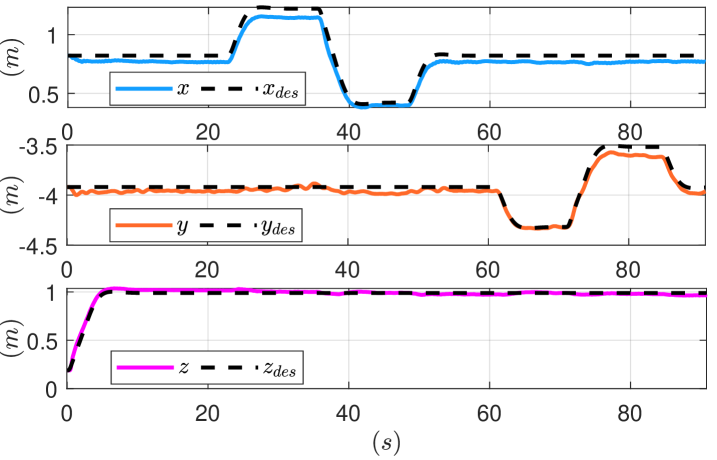
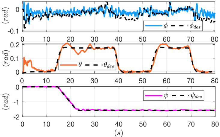
The first experiments evaluated trajectory tracking capabilities in Cartesian space. Firstly, desired position set-points , , and were sent to the aerial vehicle, and the tracking errors are displayed in Fig. 7(a). Due to the under-actuation of the system, the desired roll set points were generated from the corresponding linear motion of the platform as in eq. 15. Later, desired pitch and yaw set points and were sent to the aerial vehicle while hovering. The attitude tracking errors are displayed in Fig. 7(b). The testing results show the designed system’s promising orientation and position control during free flight with the proposed control law.
VI-C Scenario 1
In this scenario, we conducted a series of pushing tasks on a vertical work surface to evaluate the feasibility and effectiveness of the system’s dynamic \accom configuration. The high-level impedance controller in Sec. V treats the system as a mechanical admittance. To perform the pushing task, the desired contact position (i.e., the setpoint) was intentionally set “inside” the work surface, as per the approach outlined in [5]. We denote as the distance from the work surface to the setpoint along the interaction axis , with indicating positions “inside” the surface.
Using the experimental data, the pushing force perpendicular to the surface was estimated offline via the wrench estimation method detailed in [34, 17], utilizing the estimated thrust of each propeller. The required aerodynamic coefficients for thrust estimation were measured with an RC Benchmark Thrust Stand, with more details available in [30]. To initiate contact with the surface, a setpoint of was provided to the high-level impedance controller, resulting in the platform exerting approximately of pushing force, see Fig. 8. While maintaining contact, the shifting-mass plate moved actively toward the work surface, reaching its maximum allowable position at , thus dynamically displacing the \accom. This process is demonstrated in the first part of the accompanying video111The video is available at https://youtu.be/NXEnCS1ZLEg..
With the shifting-mass plate at , setpoints of were then provided to command progressively higher pushing forces. The platform stably pushed against the vertical surface with forces of , , and , respectively (see Fig. 8). By moving the \accom closer to the front rotors, as described in Sec. II-A, the system was able to achieve stable pushing forces nearly equal to its gravitational force by tilting only the back rotors.
VI-D Scenario 2
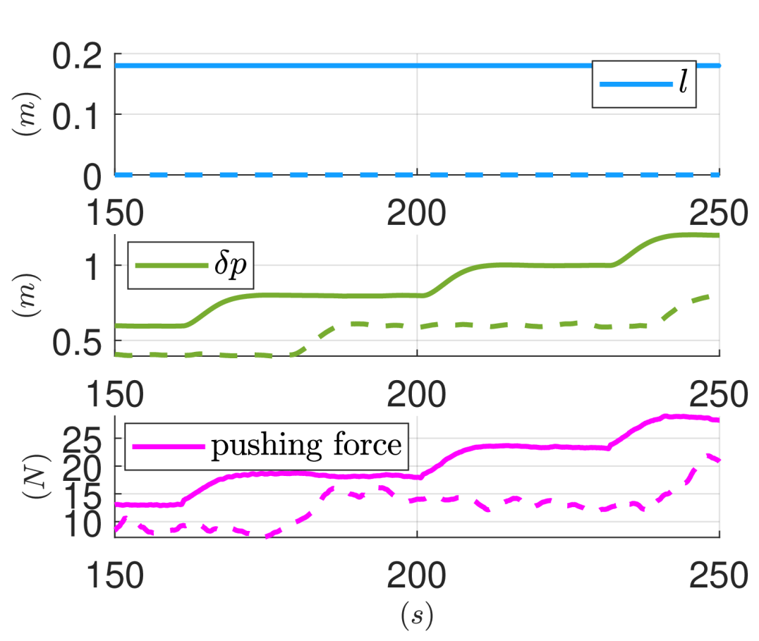
Similar to Scenario 1, a series of setpoints with varying values were used to conduct pushing tasks. However, in this case, the system’s \accom remained static, with the shifting-mass plate fixed at , as depicted in Fig. 8. Throughout the tests, the platform exhibited more pronounced oscillations compared to Scenario 1, as shown in Fig. 8 and the second part of the attached video11footnotemark: 1. Initially, a setpoint of was provided, resulting in an exerted pushing force of approximately . Subsequently, the platform applied a pushing force of about with a setpoint of . However, when the setpoint was increased to , the system impulsively generated a force of , leading to risky conditions.
VI-E Comparison with the existing platforms
| System | Mass (kg) | DoF | Num. of Tilting Axes for Pushing | |
|---|---|---|---|---|
| s1(scenario 1) | 5 | 1 | 0.92 | |
| s1(scenario 2) | 5 | 1 | 0.49 | |
| s2 [13] | 5 | 2 | 0.62 | |
| s3 [20] | 6 | 1 | 0.76 | |
| s4 [6] | 1.50 | 4 | 2 | 0.51 |
In this section, we compare the force generation capability of the proposed system with various state-of-the-art (SOTA) aerial manipulation platforms. To evaluate force exertion on vertical surfaces during pushing tasks, we consider key parameters for each system: total system mass (), the number of actuation \acdof, the number of tilting rotor axes engaged for pushing (), and the maximum achievable pushing force (). Additionally, we introduce a comparison factor that accounts for both the platform’s mass and the number of tilting axes used for pushing:
| (19) |
where a higher value of indicates superior force exertion ability. Table I shows the comparison of our proposed system with SOTA platforms. System s2 [13], a 5-\acdof platform, tilts both front and back rotors to generate pushing forces. It exerts a pushing force of with a mass of and two tilting axes. System s3 [20], a 6-\acdof platform, generates up to of stable pushing force, with a mass of and one tilting axis for pushing. System s4 [6], featuring 4-\acdof actuation, can apply up to on a vertical surface with a weight of . It uses both front and back rotors for pushing, similar to the configuration in system s2 [13], with .
In comparison, our proposed system, with only one tilting axis (the back rotors) and a lightweight structure (), can exert a stable pushing force of when the \accom is dynamically displaced closer to the front rotors as in Scenario 1. With a fixed \accom as in Scenario 2, it can push up to with more oscillations.
This quantitative comparison highlights the effectiveness of our approach, demonstrating that the proposed system achieves competitive force generation with fewer tilting axes thanks to the dynamic \accom displacing configuration.
VII Conclusion
In this work, we introduced a novel approach to enhance force generation in aerial manipulation systems by focusing on the system’s \accom location. Through an analysis of how the \accom affects interaction forces, we proposed an innovative platform design featuring a dynamic \accom displacing configuration. By shifting the \accom closer to the front rotors during interactions, the system is capable of generating significantly higher pushing forces. The effectiveness of this design was validated through physical experiments using an aerial vehicle equipped with tilting back rotors, achieving a stable pushing force nearly equal to the system’s own weight. Additionally, we introduced a quantitative factor for comparing the force exertion capabilities of our system against existing platforms, demonstrating the clear advantages of our approach. This work paves the way for the development of a new class of aerial vehicles with enhanced tool manipulation capabilities, opening up promising directions for future research and applications.
References
- [1] Bogue, R. (2018), ”What are the prospects for robots in the construction industry?”, Industrial Robot, Vol. 45 No. 1, pp. 1-6. https://doi-org.proxy.findit.cvt.dk/10.1108/IR-11-2017-0194.
- [2] F. Ruggiero, V. Lippiello and A. Ollero, ”Aerial Manipulation: A Literature Review,” in IEEE Robotics and Automation Letters, vol. 3, no. 3, pp. 1957-1964, July 2018, doi: 10.1109/LRA.2018.2808541.
- [3] Y. Sun, A. Plowcha, M. Nail, S. Elbaum, B. Terry and C. Detweiler, ”Unmanned Aerial Auger for Underground Sensor Installation,” 2018 IEEE/RSJ International Conference on Intelligent Robots and Systems (IROS), Madrid, Spain, 2018, pp. 1374-1381, doi: 10.1109/IROS.2018.8593824.
- [4] R. Dautzenberg et al., ”A Perching and Tilting Aerial Robot for Precise and Versatile Power Tool Work on Vertical Walls,” 2023 IEEE/RSJ International Conference on Intelligent Robots and Systems (IROS), Detroit, MI, USA, 2023, pp. 1094-1101, doi: 10.1109/IROS55552.2023.10342274.
- [5] A. Ollero, M. Tognon, A. Suarez, D. Lee and A. Franchi, ”Past, Present, and Future of Aerial Robotic Manipulators,” in IEEE Transactions on Robotics, vol. 38, no. 1, pp. 626-645, Feb. 2022, doi: 10.1109/TRO.2021.3084395.
- [6] H. W. Wopereis, J. J. Hoekstra, T. H. Post, G. A. Folkertsma, S. Stramigioli and M. Fumagalli, ”Application of substantial and sustained force to vertical surfaces using a quadrotor,” 2017 IEEE International Conference on Robotics and Automation (ICRA), Singapore, 2017, pp. 2704-2709, doi: 10.1109/ICRA.2017.7989314.
- [7] S. Kim, S. Choi and H. J. Kim, ”Aerial manipulation using a quadrotor with a two DOF robotic arm,” 2013 IEEE/RSJ International Conference on Intelligent Robots and Systems, Tokyo, Japan, 2013, pp. 4990-4995, doi: 10.1109/IROS.2013.6697077.
- [8] Trujillo, M.Á.; Martínez-de Dios, J.R.; Martín, C.; Viguria, A.; Ollero, A. Novel Aerial Manipulator for Accurate and Robust Industrial NDT Contact Inspection: A New Tool for the Oil and Gas Inspection Industry. Sensors 2019, 19, 1305. https://doi.org/10.3390/s19061305
- [9] M. Ryll, G. Muscio, F. Pierri, E. Cataldi, G. Antonelli, F. Cac- cavale, D. Bicego, A. Franchi, 6d interaction control with aerial robots: The flying end-effector paradigm, The Inter- national Journal of Robotics Research 38 (2019) 1045–1062. doi:10.1177/0278364919856694.
- [10] S. Park, J. Lee, J. Ahn, M. Kim, J. Her, G.-H. Yang, D. Lee, Odar: Aerial manipulation platform enabling omnidirectional wrench generation, IEEE/ASME Transactions on Mechatronics 23 (2018) 1907–1918. doi:10.1109/TMECH.2018.2848255.
- [11] R. Watson et al., ”Dry Coupled Ultrasonic Non-Destructive Evaluation Using an Over-Actuated Unmanned Aerial Vehicle,” in IEEE Transactions on Automation Science and Engineering, vol. 19, no. 4, pp. 2874-2889, Oct. 2022, doi: 10.1109/TASE.2021.3094966.
- [12] C. Ding and L. Lu, ”A Tilting-Rotor Unmanned Aerial Vehicle for Enhanced Aerial Locomotion and Manipulation Capabilities: Design, Control, and Applications,” in IEEE/ASME Transactions on Mechatronics, vol. 26, no. 4, pp. 2237-2248, Aug. 2021, doi: 10.1109/TMECH.2020.3036346.
- [13] S. Hwang, D. Lee, C. Kim and H. J. Kim, ”Autonomous Heavy Object Pushing Using a Coaxial Tiltrotor,” in IEEE Transactions on Automation Science and Engineering, doi: 10.1109/TASE.2024.3409058.
- [14] H. -N. Nguyen, S. Park, J. Park and D. Lee, ”A Novel Robotic Platform for Aerial Manipulation Using Quadrotors as Rotating Thrust Generators,” in IEEE Transactions on Robotics, vol. 34, no. 2, pp. 353-369, April 2018, doi: 10.1109/TRO.2018.2791604.
- [15] F. Ruggiero et al., ”A multilayer control for multirotor UAVs equipped with a servo robot arm,” 2015 IEEE International Conference on Robotics and Automation (ICRA), Seattle, WA, USA, 2015, pp. 4014-4020, doi: 10.1109/ICRA.2015.7139760.
- [16] M.A. Elbestawi, K.M. Yuen, A.K. Srivastava, H. Dai, Adaptive Force Control for Robotic Disk Grinding, CIRP Annals, Volume 40, Issue 1, 1991, Pages 391-394, ISSN 0007-8506, https://doi.org/10.1016/S0007-8506(07)62014-9.
- [17] T. Hui and M. Fumagalli, ”Static-Equilibrium Oriented Interaction Force Modeling and Control of Aerial Manipulation with Uni-Directional Thrust Multirotors,” 2023 IEEE/ASME International Conference on Advanced Intelligent Mechatronics (AIM), Seattle, WA, USA, 2023, pp. 452-459, doi: 10.1109/AIM46323.2023.10196117.
- [18] T. Hui, M. J. Fernandez Gonzalez, and M. Fumagalli, ”Safety-Conscious Pushing on Diverse Oriented Surfaces with Underactuated Aerial Vehicles,” 2024 International Conference on Robotics and Automation (ICRA), Yokohama, Japan, 2024, doi: arXiv:2402.15243.
- [19] T. Hui, E. Cuniato, M. Pantic, M. Tognon,M. Fumagalli, and R. Siegwart, ”Passive Aligning Physical Interaction of Fully-Actuated Aerial Vehicles for Pushing Tasks,” 2024 International Conference on Robotics and Automation (ICRA), Yokohama, Japan, 2024, doi: arXiv:2402.17434v1.
- [20] T. Hui, F. Braun, N. Scheidt, M. Fehr, and M. Fumagalli, Versa- tile airborne ultrasonic ndt technologies via active omni-sliding with over-actuated aerial vehicles, in: M. H. Ang Jr, O. Khatib (Eds.), Experimental Robotics, Springer Nature Switzerland, Cham, 2024, pp. 450–460. doi:https://doi.org/10.1007/ 978-3-031-63596-0-40.
- [21] J. Meng, J. Buzzatto,Y. Liu, M. Liarokapis. On Aerial Robots with Grasping and Perching Capabilities: A Comprehensive Review. Front Robot AI. 2022 Mar 25;8:739173. doi: 10.3389/frobt.2021.739173.
- [22] S. B. Backus, L. U. Odhner and A. M. Dollar, ”Design of hands for aerial manipulation: Actuator number and routing for grasping and perching,” 2014 IEEE/RSJ International Conference on Intelligent Robots and Systems, Chicago, IL, USA, 2014, pp. 34-40, doi: 10.1109/IROS.2014.6942537.
- [23] H. Zhang, J. Sun and J. Zhao, ”Compliant Bistable Gripper for Aerial Perching and Grasping,” 2019 International Conference on Robotics and Automation (ICRA), Montreal, QC, Canada, 2019, pp. 1248-1253, doi: 10.1109/ICRA.2019.8793936.
- [24] L. Daler, A. Klaptocz, A. Briod, M. Sitti and D. Floreano, ”A perching mechanism for flying robots using a fibre-based adhesive,” 2013 IEEE International Conference on Robotics and Automation, Karlsruhe, Germany, 2013, pp. 4433-4438, doi: 10.1109/ICRA.2013.6631206.
- [25] H. W. Wopereis, T. D. van der Molen, T. H. Post, S. Stramigioli and M. Fumagalli, ”Mechanism for perching on smooth surfaces using aerial impacts,” 2016 IEEE International Symposium on Safety, Security, and Rescue Robotics (SSRR), Lausanne, Switzerland, 2016, pp. 154-159, doi: 10.1109/SSRR.2016.7784292.
- [26] A. McLaren, Z. Fitzgerald, G. Gao and M. Liarokapis, ”A Passive Closing, Tendon Driven, Adaptive Robot Hand for Ultra-Fast, Aerial Grasping and Perching,” 2019 IEEE/RSJ International Conference on Intelligent Robots and Systems (IROS), Macau, China, 2019, pp. 5602-5607, doi: 10.1109/IROS40897.2019.8968076.
- [27] K. Bodie et al., “An omnidirectional aerial manipulation platform for contact-based inspection,” in Proc. Robot.: Sci. Syst., 2019.
- [28] F. Goodarzi, D. Lee and T. Lee, ”Geometric nonlinear PID control of a quadrotor UAV on SE(3),” 2013 European Control Conference (ECC), Zurich, Switzerland, 2013, pp. 3845-3850, doi: 10.23919/ECC.2013.6669644.
- [29] M. Kamel et al., ”The Voliro Omniorientational Hexacopter: An Agile and Maneuverable Tiltable-Rotor Aerial Vehicle,” in IEEE Robotics & Automation Magazine, vol. 25, no. 4, pp. 34-44, Dec. 2018, doi: 10.1109/MRA.2018.2866758.
- [30] T. Hui, E. Zamora, S. D’Angelo, S. Rucareanu, M. Fumagalli, ”AEROBULL: A Center-of-Mass Displacing Aerial Vehicle Enabling Efficient High-Force Interaction,” 2024, https://doi.org/10.48550/arXiv.2408.15008.
- [31] L. Meier, D. Honegger and M. Pollefeys, ”PX4: A node-based multithreaded open source robotics framework for deeply embedded platforms,” 2015 IEEE International Conference on Robotics and Automation (ICRA), Seattle, WA, USA, 2015, pp. 6235-6240, doi: 10.1109/ICRA.2015.7140074.
- [32] S. D’Angelo, F. Pagano, F. Longobardi, F. Ruggiero and V. Lippiello, ”Efficient Development of Model-Based Controllers in PX4 Firmware: A Template-Based Customization Approach,” 2024 International Conference on Unmanned Aircraft Systems (ICUAS), Chania - Crete, Greece, 2024, pp. 1155-1162, doi: 10.1109/ICUAS60882.2024.10556938.
- [33] T. Hui et al., ”Centroidal Aerodynamic Modeling and Control of Flying Multibody Robots,” 2022 International Conference on Robotics and Automation (ICRA), Philadelphia, PA, USA, 2022, pp. 2017-2023, doi: 10.1109/ICRA46639.2022.9812147.
- [34] T. Tomić, C. Ott and S. Haddadin, ”External Wrench Estimation, Collision Detection, and Reflex Reaction for Flying Robots,” in IEEE Transactions on Robotics, vol. 33, no. 6, pp. 1467-1482, Dec. 2017, doi: 10.1109/TRO.2017.2750703.