Edge-powered Assisted Driving
For Connected Cars
Abstract
Assisted driving for connected cars is one of the main applications that 5G-and-beyond networks shall support. In this work, we propose an assisted driving system leveraging the synergy between connected vehicles and the edge of the network infrastructure, in order to envision global traffic policies that can effectively drive local decisions. Local decisions concern individual vehicles, e.g., which vehicle should perform a lane-change manoeuvre and when; global decisions, instead, involve whole traffic flows. Such decisions are made at different time scales by different entities, which are integrated within an edge-based architecture and can share information. In particular, we leverage a queuing-based model and formulate an optimization problem to make global decisions on traffic flows. To cope with the problem complexity, we then develop an iterative, linear-time complexity algorithm called Bottleneck Hunting (BH). We show the performance of our solution using a realistic simulation framework, integrating a Python engine with ns-3 and SUMO, and considering two relevant services, namely, lane change assistance and navigation, in a real-world scenario. Results demonstrate that our solution leads to a reduction of the vehicles’ travel times by 66% in the case of lane change assistance and by 20% for navigation, compared to traditional, local-coordination approaches.
Index Terms:
Vehicular networks; road traffic management; queuing theory.1 Introduction
5G-and-beyond networks are expected to support critical mobile services requiring ultra-low latency and ultra-high reliability. Among these, automotive services are pivotal to the increase of road safety and traffic efficiency, promising a substantial reduction in terms of car accidents and road congestion, as well as a significant improvement for the environment and in both people’s life quality [1] and health.
In particular, both the number of accidents and traffic congestion can be effectively decreased by enabling vehicles to coordinate their movements with each other. Techniques for vehicle coordination and their impact have been investigated in various scenarios and targeting different use cases, ranging from lane change and lane merge in highways [2] to collision avoidance at intersections [3] and traffic light management [4]. More recently, the advent of connected and automated vehicles, equipped with sensing, computing, and communication capabilities, has spurred a dramatic revival of interest in assisted driving. Examples confirming this trend include the activity within research projects like AutoNet2030 [5], 5GCAR [6], and 5G-TRANSFORMER [7], as well as the one by standardization organizations focusing on cooperative intelligent transportation services [8].
In spite of the above research efforts aimed at developing effective assisted driving systems, several challenges still have to be solved. In particular, all existing solutions (including the standardized ones) leverage local decisions (i.e., made by each ego vehicle), based on the information collected from neighboring vehicles. Although being locally made, such decisions have an impact on the vehicle traffic flow as a whole, hence, on the behavior of vehicles that may be even very far away from the ego one.
Predicting and controlling the consequences of local decisions is a daunting task. To face such a problem, we envision a system architecture, first introduced in our conference paper [9], that exploits the synergy between the vehicular network and the edge of the network infrastructure. Such architecture comprises two logical layers, one concerned with vehicular flows and in charge of defining suitable strategies to optimize them, the other addressing the movement of the individual vehicles on a shorter time span and generating instructions for specific manoeuvres. More in detail, we envision a system including:
-
•
an edge server (e.g., located within the city metro node), which, leveraging existing queuing-based models, computes traffic flow policies, for each vehicle flow, aiming at reducing the flow travel time;
-
•
a set of servers in the radio access network, e.g., residing at cellular base stations or road-side units (RSUs), which translate such policies into individual instructions for the single vehicles. These servers, also referred to as actualizers in the rest of the paper, are in charge of delivering the individual instructions to the vehicles so as to match the aforementioned flow policies on the longer run;
-
•
connected and automated vehicles, who receive the above instructions and perform the suggested manoeuvre by coordinating with their neighbors through vehicle-to-vehicle (V2V) communications.
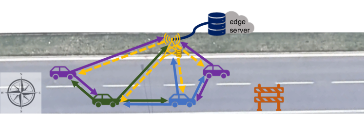
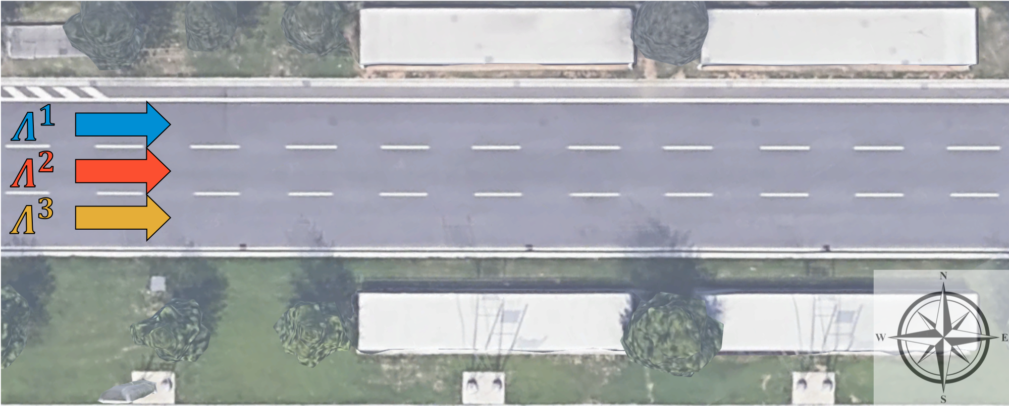
An example of the above architecture referring to the lane change use case is presented in Fig. 1. Here, a policy may instruct 30% of the cars on the south lane to move left early on, i.e., as early as where the green car is, and the others to change lane later on, i.e., where the blue car is. To enact this policy, the road-side actualizer instructs the approaching cars accordingly, and the vehicles receiving the lane change command interact with their neighbors, following, e.g., the protocol in [5], and perform the manoeuvre. Notice how the actualizer does not change the policies decided by the edge server, but it enforces them by translating them into local, vehicle-specific instructions. At the same time, policies do not compel the actualizer to choose any particular action for any particular vehicle; indeed, the edge server does not have any visibility over individual vehicles – which makes computing policies easier and faster.
The communication between the network infrastructure (and the servers therein) and the vehicles, as well as V2V communications, occur using standard protocols and messages (e.g., [8]). Nevertheless, since the individual instructions conveyed by the actualizer to the vehicles realize the policies computed by the edge server, the system can attain local objectives (e.g., avoiding car accidents) as well as global ones (e.g., reducing traffic congestion).
The effectiveness of the above architecture and information flow, however, depend upon the quality of the traffic flow policies. Indeed, the task of computing optimal policies at the edge server is still very challenging, due to the following reasons:
-
(i)
policies have to account for the different destinations of the vehicles currently traveling over the same stretch of road, and for how the behavior of such vehicles can affect each other’s travel time;
-
(ii)
to attain fair policies, it is essential to consider the vehicles travel time distribution, rather than relaying on the average travel time only;
-
(iii)
in addition to being as effective as possible, policies must be computed efficiently so as to provide real-time driving assistance.
In this paper, we tackle the above issues by providing the following main contributions:
System architecture: we design a system architecture, based on the edge computing paradigm [10, 11, 12, 13, 14], integrating connected cars and the edge of the network architecture, with the latter hosting a traffic controller in charge of providing traffic flow policies (Sec. 3);
Analytical modeling and optimization: leveraging existing works on queue-based models for vehicular traffic (see Sec. 2 next), we present in Sec. 4 a model that can represent arbitrary road topologies as well as any path followed by the vehicles, and which allows for the computation of the vehicles’ travel times distribution (as opposed to a simple average), as detailed in Sec. 5. Through this model, we derive the distribution of the vehicles’ travel times, and formulate the problem of optimizing such distribution (Sec. 6);
Algorithm: we present and analyze an optimal algorithm, inspired by gradient-descent and named Bottleneck Hunting (BH), that provides optimal traffic flow policies in linear time (Sec. 7);
Realistic simulation framework and performance evaluation: we leverage a simulation framework including a Python engine we developed, the ns-3 network simulator, and the SUMO mobility simulator. Through such simulator, we capture the main aspects of real-world assisted driving systems (Sec. 8) and assess the performance of the BH algorithm in real-world use cases, showing the gain we can obtain with respect to traditional, distributed strategies (Sec. 9).
Finally, we conclude the paper in Sec. 10.
2 Related work
Queuing theory has often been used for mesoscopic models of vehicular traffic, on both individual road stretches and more complex road layouts. In such models, customers in queues represent the vehicles traversing the road topology [15, 16, 17, 18], while, in the case of straight road stretches, queue service times model the vehicle travel times.
Owing to the power and flexibility of the queuing abstraction, queues have also been consistently and effectively used to represent congested traffic conditions [15] – indeed, queuing theory can well address the causes and effects of congestion. The pioneering work in [19] argues that the arrival of vehicles at intersections, either individually or in batches, can be represented as a Poisson process. The study in [20] proposes to model urban topologies as a set of elementary (namely, and ) queues, and the later work [21] leverages empirical validation to argue for a more general, model in non-congested scenarios. In both cases, individual lanes are each associated with a queue. The later work [17] finds that, under free-flow conditions, the probability that any road segment attains its full capacity is zero, therefore, it is appropriate to model such segments through queues with an infinite number of servers, namely, of type .
Vehicular mobility is modeled through queues also in several recent works about edge and cloud computing in vehicular networks, including [22, 23, 24]. Similarly, the work [16] leverages Poisson arrivals to characterize the connectivity of VANETs in highway-like scenarios.
Other works, e.g., [25], focus on specific aspects of vehicular traffic, such as modeling the delay of indisciplined traffic (where motorbikes and cars do not respect lanes) at regulated intersections traffic [25], or on estimating the error incurred by probe vehicles [26]. In both cases, models are found to accurately represent real-world conditions. Similarly, [25] shows that indisciplined traffic can be modeled via queues, and [27] uses them to study congestion in vehicular networks. Consistently, the study in [28], based on realistic simulations, finds to well represent travel time on individual road segments. Note that part of the popularity of Markovian service times is due to their ability to capture the effect of heterogeneous traffic (e.g., cars, trucks,…) [25], proceeding at different speeds. Batch arrival and departure processes are the modeling tool of choice when traffic signals are involved, e.g., [29, 30]. In all cases, arrivals are assumed to be Markovian in nature, while service times are either Markovian or deterministic.
Situations where vehicles from multiple flows have to merge into one lane has been identified as a major cause of congestion. Accordingly, several research efforts focus on modeling the merging behavior of vehicles [31], as well as on devising optimized merging strategies [32]. Among merging situations, several works [33] focus on access ramps to highways, which are especially critical because of the different speeds of incoming vehicles. Other works, e.g., [34], focus on communication aspects, especially the channel conditions experienced by merging vehicles in urban scenarios. Recent efforts such as [2] deal with merging strategies for autonomous vehicles, and the benefits coming from cooperation between them.
Traffic accidents, along with their causes and consequences, have long been studied in the literature. As an example, [35] aims at characterizing the duration of accidents and the factors that could mitigate their consequences, e.g., better infrastructure maintenance. Closer to one of the scenarios we consider, [36] considers the case of a multi-lane road, where one of the lanes is blocked by an accident. The authors of [36], however, model the whole road as a single queue, that is, with multiple servers () drawing from the same queue. Conversely, beside having a different scope, we model a multiple-lane road stretch through multiple one-server queues.
Focusing on the specific aspect of lane-change behavior, [37] combines queuing theory, to describe the mobility of vehicles, and game theory, to model the self-interested decisions they make. With a different goal but using the same tools, [38] leverages queuing theory to detect the users most likely to attempt a lane change, before they do so.
The general problem of harmonizing and optimizing multiple flows of vehicles through a road network has received considerable attention from the research community. In particular, [39] envisions switching between flow- and phase-based control of traffic lights based on real-time traffic conditions. [24], instead, accounts for the available radio coverage while making flow-routing decisions, to ensure that each vehicle gets the bandwidth it needs. Taking a dual approach, [40] aims at identifying clusters of vehicles traveling together and using them as “vehicular clouds” to perform computation tasks. Early works focus on individual intersections and study how to model their behavior through queuing-based models. For instance, such models are leveraged in [4] to program an intelligent traffic light reacting to traffic conditions.
Among recent solutions leveraging edge computing in intelligent transportation systems (ITS) scenarios, many focus on providing safety-critical services like collision avoidance via edge servers [13, 14], with special emphasis on vulnerable users such as pedestrians and bicycle riders [13]. A more general approach is adopted in [11, 12], targeting the problem of placing any ITS service leveraging both edge and cloud resources.
Finally, a preliminary version of this work has been presented in the conference paper [9]. With respect to [9], this paper greatly expands the scope of the model (which now includes batch arrivals), the characterization of the problem (even when no closed-form solution exists), the analysis of the algorithm (which we prove to have linear complexity), as well as the results (which we expand from one to three reference scenarios).
Novelty. In this paper, we leverage existing works on queue models for vehicular networks and existing edge-based architectures in order to provide high-quality assistance to connected vehicles. Specifically, unlike existing works, we drive local decisions through vehicle flow policies, which account for the global effects of local behaviors. Thus, while other edge-based approaches foresee only one decision-making entity, in our solution global and local decisions are made by different entities, integrated into an edge-based architecture and able to operate at different time scales, while sharing information and policies. Furthermore, our decision-making scheme accounts for the whole distribution of flow-wise trip-times, as opposed to simple averages thereof. We prove that such a scheme is scalable under a wide variety of modeling assumptions and scenarios. Finally, our algorithm outperforms generic optimization algorithms by exploiting problem-specific information to further speed-up the decision process.
3 System architecture
We now introduce the architecture we envision, highlighting how it is consistent with existing standards on connected vehicle communications. According to the ETSI 102.941 (2019) standard, connected vehicles periodically (e.g., every 100 ms) broadcast cooperative awareness messages (CAMs), including their location, speed, and heading. Such information is then used by other vehicles and/or the network infrastructure for several safety and convenience services, e.g., collision avoidance [41]. Upon detecting a situation warranting action (e.g., two vehicles on a collision course), decentralized environmental notification messages (DENMs) are sent to the affected vehicles, so that their actualizer is triggered and/or their driver is warned. Both CAMs and DENMs can carry additional information [8] for the support of assisted driving services such as lane change/merge [8] and navigation services (see ETSI 102.638).
None of the above is envisioned to change under our proposed architecture; in particular, all services still leverage the transmission of CAMs and DENMs. For concreteness, we focus on the lane change assistance and navigation services. In the first case, the edge server exploits the information in the CAMs received by the radio access nodes (and possibly notifications of lane blocks carried by DENMs) to formulate an optimal policy. Such a policy is then sent to the actualizers, which, being closer to the mobile users, can account for the most recent CAMs and exploit them to translate the policy into individual instructions for the single vehicles (see Fig. 1). These instructions are notified to vehicles through DENMs sent by the radio access nodes. Upon receiving a DENM, a vehicle starts interacting via V2V communications with its neighbors following, e.g., the protocol defined in [5] and using CAMs and DENMs as foreseen by [8].
The second service (navigation) operates on a longer time and larger geographical scale: the edge server exploits the CAMs and, in particular, the route destination field therein, and computes the optimal vehicles’ route. This is then notified by the radio access nodes using DENMs.
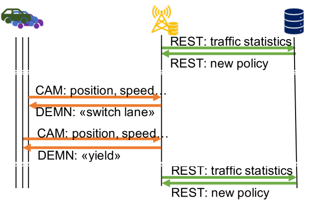
Fig. 2 exemplifies the messages between vehicles, RSUs (acting as actualizers), and the edge server in the lane-changing scenario. The vehicles and the RSU exchange messages standardized by ETSI 102.941, e.g., CAMs and DEMNs, represented by orange lines in Fig. 2. CAMs convey information on (respectively) the vehicle’s status, including its position, speed, heading, acceleration, and intentions (e.g., turn signals); DEMN messages, instead, convey indications on what vehicles should do, e.g., switch lane.
RSUs and edge server, instead, communicate through HTTP-based REST exchanges, corresponding to green lines in the figure: RSUs periodically send reports on the traffic they observe, and the edge server leverages such information to periodically issue new general vehicle flow policies. RSUs account for the currently-active policies when sending out DEMN messages, e.g., to decide how many vehicles to instruct to yield.
Notice that RSUs are not required to communicate directly; however, if such an option is available, it can be exploited. Specifically, one of the RSU servers can also function as a policy server, and therefore communicate directly with other RSUs to distribute policies. Indeed, policy maker and actualizer are logical roles, which can be assigned to any physical node, provided it has the required capabilities.
For all services, latency is a foremost concern; indeed, carefully-crafted policies and individualized suggestions are no use if they come too late. Edge-based solutions such as ours have longer latency than purely V2V ones. However, previous works on collision avoidance [13, 14] have shown that such additional delay is negligible compared to the overall reaction times, and more than compensated by the additional information that can be leveraged. It is worth noticing that collision-avoidance services have extremely tight latency requirements, thus, the findings of [13, 14] also apply to, e.g., lane-changing assistance.
Placing the server at the network edge yields the optimal trade-off between the availability of global information and the need for low latency. As discussed earlier, edge servers have remarkably short latencies, compatible with critical safety services. At the same time, they oversee fairly large areas, e.g., a neighborhood or a small town; it follows that the information they collect is sufficiently general to allow high-quality, global decisions. If the service (e.g., navigation) and the scenario (e.g., large urban areas) warrant it, multiple edge servers can coordinate and synchronize via the Internet cloud.
Throughout this paper, for simplicity, we refer to a single edge server. However, it is important to highlight that, for very complex and/or large scenarios, multiple edge servers can coexist, each responsible for a subset of the topology. This allows the edge servers to make decisions more efficiently, while retaining their ability to account for their far-reaching effects. Importantly, different services require edge servers to supervise areas of different sizes: for a lane change service, the area supervised by a single edge server can be as small as a single stretch of road; for navigation services, it can be as large as a neighborhood or small town. In the latter case, however, decisions can be made less frequently, hence, the load on the edge server remains manageable.
It is also important to highlight how, as also exemplified in Fig. 2, actualizers and policy servers operate at different time scales. Indeed, actualizers can immediately react to messages coming from vehicles according to the current policy, without the need for the policy server to intervene. Through such a logical separation between policy servers and actualizers, our solution is able to leverage global knowledge when making local decisions.
4 Model design
In this section, we describe how our system model represents the road layout, the vehicle flows (Sec. 4.1), the routes taken by vehicles in the same flow, and their travel times (Sec. 4.2). With the aim to devise efficient policies at the edge server, we represent traffic flows by queuing models, so as to capture the flow dynamics depending on aggregate quantities such as the road capacity. Importantly,
- •
-
•
we do not restrict ourselves to a specific service time distribution or number of servers, supporting instead a very wide range of queuing models;
-
•
given the scope of our work, we focus on uncongested scenarios where the number of vehicles traveling on a road stretch is lower than its capacity, hence road stretches can be modeled with queues with infinite length.
The decisions to be made correspond, intuitively, to the policies formulated by the edge server in Fig. 1. Specifically, they consist of the suggested travel speed and the probabilities of taking a given lane/stretch of road. In the following, we refer to a single lane on a stretch of road as road segment.
4.1 Road topologies as queue networks
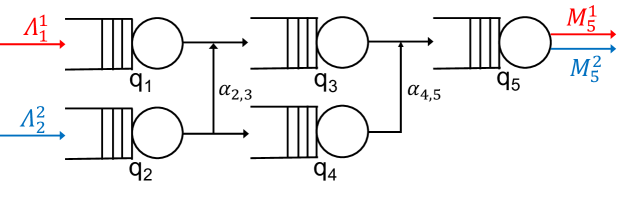
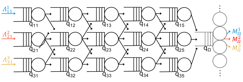
Similar to existing works [11, 12, 16, 17], we model the road topology under the control of the edge server as a set of interconnected queues , as exemplified in Fig. 3. Similarly to existing works (including experimental validation [21, 17]), each queue represents a road segment, characterized by, e.g., a certain speed limit and capacity.
Service rates, , are bounded by a maximum value , determined by the length of the road segment modeled by queue , its speed limit, and the inter-vehicle safety distance:
| (1) |
Several traffic flows, , may travel across the road topology or part of it, each flow being defined as a set of vehicles having the same source and destination within the road topology. Specifically, given a flow entering and leaving the road topology at queue and , respectively, the parameter denotes the vehicles arrival rate, while parameter denotes the rate at which they exit the topology. For every flow , there is exactly one queue for which and one queue for which (see Fig. 3); furthermore, these two quantities are the same, as all vehicles of the flow begin their route at queue and end it at queue . Note that and are known parameters for the algorithms, which can be obtained by the edge server leveraging the CAMs periodically transmitted by the vehicles. Vehicles move from a generic queue to queue according to probability .
Given the above model, our decision variables are the service rates of queues , and the transition probabilities (although some can be fixed, e.g., in Fig. 3, ). The total incoming flow for queue is denoted with and depends on , , ; it is given by:
| (2) |
where denotes the probability that queue is empty. Eq. (2) can be read as follows: the flow entering queue is equal to the flow of vehicles that begin their journey therein, plus a fraction of the vehicles that exit other queues , but do not leave yet the road topology.
4.2 A path-based view
Modeling road topologies as queue networks [11, 12, 16, 17] is a sensible methodology to estimate the travel times of different vehicles or group thereof. However, it is often cumbersome to make decisions based on queue models, owing to the large number of variables therein (the routing probabilities) and the complex way in which such probabilities influence the distribution of the travel times of vehicles of the same flow. To allow for quicker and higher-quality decisions, we now leverage the notion of path, i.e., a sequence of queues with a given source and destination, and per-flow path probabilities.
Vehicle with the same source and destination are said to belong to a flow , with identifying the set of flows. Edge servers can obtain information on the vehicles’ destination from the CAMs they send, or through application-layer communication. Indeed, it is fair to assume that vehicles benefiting from a service, e.g., navigation, agree to disclose their destination, provided that proper anonymization and privacy mechanisms [42] are in place.
Vehicles of the same flow may nonetheless follow different trajectories, hence, traverse different sequences of queues. We define such sequences of queues as paths . Each path is an array including the queues traversed by vehicles taking it; given a queue , we write if path includes . The probability that vehicles of flow take path is denoted by ; each path is used by one flow only, indicated as . Introducing paths allows for a flexible relationship between flows and queues, thus enhancing the realism of our model, while keeping its computational complexity low. Indeed, the set and the values can be pre-computed, hence, they do not impact the complexity of the decision-making algorithm.
Example 1 (Path-based view)
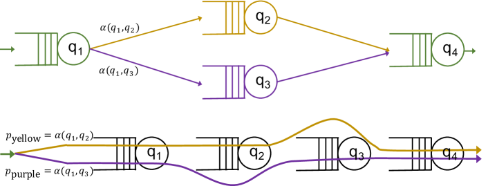
Consider a single flow and the topology in Fig. 4(top), where vehicles visit , then either or , and then . Since there are two routes that the vehicles can follow, there are two paths in , namely, and . As for the probabilities with which each path is taken, they depend on the transition probability and ; specifically, and . The resulting parallel-path view is displayed in Fig. 4(bottom).
Importantly, given the edge-based policy, vehicles are assigned a path (according to the probabilities) at the beginning of their travel across the considered road topology, before they enter the first queue. Thus, given the path it takes, the queues traversed by a vehicle are unequivocally determined.
The probabilities that vehicles of flow take path can be expressed as a function of the probabilities as:
| (3) |
where is the -th queue included in path . Clearly, the probabilities have to sum up to one:
| (4) |
We stress that, while each path is unequivocally associated with one flow, the opposite does not hold. With reference to Fig. 3, flow is associated with one path only, while flow can use path or . As for paths and queues, there is a many-to-many relationship between them. In Fig. 3, queues and belong to one path each, queues and to two paths each, and queue to all three paths.
When considering paths, the local arrival rate at each queue in (2) depends on: the paths belongs to, the probability that flows take those paths, and the arrival rate of those flows. Specifically,
| (5) |
Notice how (5) expresses the same quantity as (2) earlier. However, (5) leverages our path-based representation, while (2) considers the elementary building blocks of the system, namely, queues and the routing probabilities between them.
5 Flow Travel Times
In the following, we leverage the path-based view of the system to characterize the travel time experienced by each flow . Let us first denote with the probability density function (pdf) of the sojourn time at an individual queue . Such pdf is a function of and , according to an expression that depends on the statistics of the queue arrival process and the service time. Then, recalling that vehicles taking path traverse all queues in , the travel time associated with path is the sum of the sojourn times at all queues therein. The pdf of such a time is the -way convolution of the individual pdfs associated with each queue, i.e., . By integrating , we compute the cumulative density functions (CDFs) and take their Laplace transform, thus obtaining:
| (6) |
where is the Laplace transform of .
Anti-transforming (6), we can obtain the CDF of the path-wise travel time: . We recall that is a function of the control variables and (i.e., ), which appear in the pdf . As mentioned, the actual form of and , as well as of the above Laplace transforms, depends on the queue arrival process and service time distribution. In many cases of interest, can be expressed as a ratio between polynomials, and anti-transformed into a summation of terms of type , as shown in Sec. 5.1.
Next, we move from paths to flows. Intuitively, the travel time of flow can be expressed as the sum of the travel times of paths ’s that can be used by vehicles of flow , each weighted by probability . We first exploit to write the probability that the travel time of a vehicle taking path exceeds a value :
| (7) |
We then move to a flow-wise equivalent of , combining the path-wise probabilities with the values , expressing the probability that a vehicle of flow takes path , and write:
| (8) |
In (8), is the flow-wise target travel time, e.g., the ratio of the distance between the flow source and destination to the desired average speed between them.
It is worth stressing that, if closed-form expressions of do not exist or are too complex to manage, the steps above can still be performed numerically, obtaining the same results. In that case, however, we do not resort to Laplace transforms, and instead directly compute the required convolutions and integrals.
5.1 M/M/1 queues and batch arrivals
For sake of concreteness and as a useful example, in the following we show how the above expressions particularize to the relevant cases [20, 21, 22, 23, 24, 16] where the road segments are modeled as or queues [28, 25], with denoting the (discrete) distribution of the vehicle batch size.
Let us start from the case and consider the per-path travel times presented in Sec. 5. Given the expression of the pdf of the sojourn time at an queue , i.e., [43], where is the step function, we can write: . Thus, the CDF is given by: , which is the ratio between two polynomials in : a numerator of degree 0 and a denominator of degree . It has one pole in and additional poles, one for each queue , at . It is well known that this expression can be decomposed into partial fractions [44]:
| (9) |
where
| (10) |
and . Anti-transforming (9), we can write the CDF of the travel time on path as:
| (11) |
In the case, vehicles arrive in batches, with size characterized by a given probability mass function (pmf). Let the pmf be , , with being the maximum batch size. The expected batch size is . Then the Laplace transform of the path travel time is [45, Sec. 4.2.1]:
| (13) |
where is the queue utilization and is the probability generation function of the batch size pmf. It is important to highlight that (13) is a ratio of polynomials in : a numerator of degree and a denominator of degree . Hence, using the same methodology as above, (13) can be decomposed into partial fractions and anti-transformed, yielding an expression of similar to (12).
6 Problem formulation
Our high-level goal is to keep the fraction of vehicles of each flow , whose travel time exceeds the target , as low as possible. To ensure fairness among vehicles of different flows, we formulate such a goal as the following min-max objective:
| (14) |
The optimization variables are the probabilities (hence the ) and the service rates , which, as also exemplified in Sec. 5.1, appear in the objective function in (14) via the CDF in (6). Ingress and egress rates and are input parameters, as are the maximum service rates and the target flow travel times . The per-queue arrival rates are auxiliary variables, whose dependency on the decision variables is specified in (5). Furthermore, we need to impose the constraints in (1) and (4).
Reconstructing the -values. Given the optimal values, the variables can be recovered by solving a system of equations of the same type as (3), where the -values are the unknown and the -values are given. The system can be linearized by taking the logarithm of all variables, i.e., re-writing (3) as: , .
The fact that the system has a unique solution is ensured by the proposition below; the intuition behind it is that the number of paths grows faster than the number of junctions, hence, there are more equations than variables. It follows that, if it exists, the solution is unique.
Proposition 1
In any topology, the number of paths is strictly higher than the number of junctions.
Proof:
Let us start with a single path, hence, zero junctions. Then junctions are added one at a time, starting from queues that are already part of at least one path; by so doing, the number of junctions increases by one. Also, a new path is created for every path that included , hence, the number of paths grows by at least one. ∎
6.1 Problem complexity and solution approaches
As the road topology may include several lanes and road stretches, it is important to understand the complexity of our problem, as well as the viable solution approaches that can be pursued. Indeed, such a complexity has an impact on the computational resources required at the edge to provide timely policy updates.
We first look at the expression for in (14), which can be fairly complex even for simple queuing systems, as exemplified in Sec. 5.1 for the case. In particular, the coefficients multiplying the exponential terms can have any sign. One may be tempted to conclude that nothing can be said about the convexity of the problem; instead, it is possible to prove that: (i) in the most general case, the expression is monotonic, namely, non-decreasing; (ii) in a wide set of relevant cases, it is convex.
Theorem 1
Proof:
The monotonicity of the objective function (14) derives from the fact that the quantity can be obtained according to (7), by computing a CDF in a specific value . CDFs are non-decreasing functions and the coefficients are probabilities, hence, non negative. It follows that the quantity within the summation of (14) is a conic combination of non-decreasing expressions, which is itself non-decreasing. Similarly, taking the (point-wise) maximum over all flows preserves monotonicity; therefore, (14) as a whole is monotonic. As for the constraints, (4) and (5) are linear, hence, they meet the requirement that equality constraints of monotonic optimization problems are affine. ∎
Monotonic optimization problems [46] can be solved by mapping them into a set of convex sub-problems. Individual sub-problems are then solved to optimality in polynomial time, while the original (monotonic) problem can be solved arbitrarily closed to the optimum, at the cost of increasing the number of sub-problems.
Thm. 1 does not rely on any specific travel time distribution, but only on it being characterized by a CDF. Indeed, Thm. 1 still holds for service time distributions that do not result in a closed-form expression of the sojourn time CDF, as, e.g., in the case of queues. The wide scope of Thm. 1 reflects the generality of our framework, which does not depend on any restrictive modeling assumption on the queue service time, but works unmodified under any service time distribution.
We can prove an additional result showing that, under mild conditions, solving the problem of optimizing (14) subject to constraints (1), (4), and (5) can be reduced to a convex problem. The key mathematical concept we leverage is log-convexity. Simply put, a function is log-convex if its logarithm is convex [47]. As an example, the service time distribution of an M/M/1 queue, for , is and its logarithm is , which is linear in , hence, convex; it follows that is log-convex. Note that log-convexity is a more restrictive condition than convexity, hence, log-convexity implies convexity.
If all queues in the system have a log-convex sojourn time pdf, then the following important result holds.
Theorem 2
Proof:
As shown in Sec. 5, computing the distribution of per-path travel times involves convolutions and integrations of the sojourn time pdfs of the individual queues. Both these operations preserve the log-convexity property [47]; it follows that, if the hypothesis holds, the per-path travel time CDFs are log convex, hence, convex.
Now, the objective function (14) is computed as per (7), by considering each CDF at a specific point . Furthermore, the coefficients are probabilities, hence, non negative. It follows that the quantity within the summation in (14) is a conic combination of convex expressions, which is itself convex. Similarly, taking the (point-wise) maximum over all flows preserves convexity; therefore, (14) as a whole is convex. As for the constraints, (4) and (5) are linear, hence, they meet the requirement that equality constraints of convex optimization problems are affine. ∎
6.2 Discussion and useful insights
Thm. 1 and Thm. 2 imply that our problem can be efficiently solved by commercial, off-the-shelf solvers like CPLEX or Gurobi, especially when the conditions of Thm. 2 hold and the problem is convex. However, numerical solvers encounter significant numerical difficulties when dealing with the objective (14). As demonstrated for instance in Sec. 5.1 for the case, the coefficients therein usually contain a ratio of products of terms: a small variation in any of the terms can change the sign of the whole coefficient and/or significantly alter its (absolute) value. The issue is compounded by the fact that such values, which can be very large, are then multiplied in (8) by probabilities , which could be very small and/or be varied by very small quantities. State-of-the-art interior-points methods are engineered to deal with both challenges, however, their convergence can be slowed down – or prevented altogether – by such numerical difficulties.
Gradient-based methods like the BFGS algorithm [48] may perform better, and more reliably (albeit more slowly) converge. The basic intuition behind gradient-based methods is to start from a feasible solution, and then improve it by performing, at every iteration, the change that results in the largest improvement of the objective function. However, we can achieve faster convergence through an ad hoc algorithm exploiting problem-specific knowledge.
To design an efficient solution, we look at the case of queues with the aim to derive some insights of general validity. In particular, an aspect worth investigating is the intuitive notion that equilibrium across queues and paths can lead to better performance. To show this and pick a suitable metric to define such equilibrium conditions, we make the observation below.
Theorem 3
Proof:
Let us consider a tagged path and two additional paths and . Without loss of generality, let us move an amount of traffic, , from queue to queue , and the same amount of traffic from to . Now, note that when we had , the transform of the sojourn time CDF (9) had a double pole in and, according to the same partial fraction decomposition rules used to compute the coefficients in (10), the path travel time distribution (see (11)) reduces to: . Moving traffic from to a means replacing the two poles in with two single poles, one in and one in . (11) then becomes: .
To prove the thesis, it must be , i.e., . Considering only the expressions multiplied by , this is equivalent to imposing:
| (15) |
We remark that the first member of (15) tends to when , and to when . To assess the behavior of (15) over the rest of its domain, we compute its derivative over , obtaining: , which must be be greater than zero. The derivative can be re-written as: . The second member is clearly non negative, since for any non-negative values of and . The quantity is equal or greater than – specifically, it has a minimum at when –, hence, the first member of the derivative is always greater or equal to . In conclusion, the derivative of the quantity at the first member of (15) is always non negative, hence, the inequality (15) is valid, hence, moving traffic from a queue to another yields a value of the CDF of the path travel time, , that is lower than , for any . Hence, the travel time increases, which proves the thesis. ∎
We can also prove the following corollary, which holds in the case of multiple paths.
Corollary 1
Let be a flow that can be routed through paths, each containing the same number of queues, and assume that, for each path , for any . Then the lowest value of the objective function in (14) is attained when .
Proof:
The proof follows from the definition of given in (8), which is a weighted sum of terms . Let us consider and such that . Moving a fraction of traffic from path to path means increasing the weight corresponding to the -term, and decreasing the weight corresponding to the -term. At the same time, considering that functions are CDFs and CDFs are non-decreasing, it also means increasing the term and decreasing the -term, which results in a larger value for , hence, for the objective function in (14). ∎
In summary, we observed first that equilibrium conditions are indeed associated with better performance. Second, the best metric to use when defining equilibrium is the difference between the service and arrival rate at each queue, i.e., . We leverage both insights while defining our algorithm, as explained next.
7 The BH algorithm
We now propose an iterative algorithm to solve the above optimization problem, and discuss its properties and novelty. We underline that the algorithm works unmodified for a very wide range of queuing models, with different arrival processes, service time distributions, and number of servers.
7.1 Goal and approach
Thm. 1 and Thm. 2 imply that our problem can be solved by performing one or more convex optimizations, even when its objective does not have a closed-form expression. A prominent family of algorithms that solve convex problems is represented by gradient-descent algorithms – from the venerable Newton algorithm to more modern alternatives such as BFGS [48] and stochastic gradient descent [49] (SGD), the latter widely used in machine-learning applications.
Gradient-descent algorithms work iteratively, by changing at each iteration one variable in the current solution, and effecting the change yielding the highest improvement in the objective function. If, as in our case, the problem is convex, any gradient-descent algorithm is guaranteed to converge to the optimal solution.
However, general-purpose algorithms such as BFGS or SGD are unaware of the underlying structure of the problem, and make their decisions in terms of individual variables, i.e., per-path probabilities. This may lead them to make changes that, due to their impact on other paths and flows, have to be undone at a later iteration; the final result is that the optimal is reached in a longer time than needed.
To avoid this problem, we design an iterative algorithm called bottleneck-hunting (BH). Our high-level design objectives can be summarized as follows: (i) follow the same philosophy as gradient-descent, i.e., iteratively improving a solution; (ii) make higher-level decisions, accounting for flows and paths instead of individual optimization variables; (iii) avoid making decisions that need to be undone at later stages. The resulting algorithm is described in Sec. 7.2 and analyzed in Sec. 7.3. It has the same worst-case performance and convergence properties of gradient-based alternatives but, thanks to its awareness of problem-specific information, it exhibits faster average-case performance.
7.2 Algorithm description
As discussed above, the BH algorithm finds a solution to the problem specified in Sec. 6 faster than general-purpose, gradient-descent-based alternatives. Such a faster convergence is achieved by leveraging problem-specific knowledge and information in order to reduce the number of solutions to try out, hence, of algorithm iterations. Specifically, Thm. 3 and Corollary 1 show that, if a solution where all queues of each path have the same load is feasible, then the solution is optimal. It follows that, in those cases, it is never necessary to widen the gap between the most- and least-loaded queues of any path. We take this as a guideline to design the BH algorithm, which iteratively improves a current solution similarly to a gradient-based approach, but avoiding widening the aforementioned gap whenever possible.
With reference to Alg. 1, at every iteration, BH moves a fraction of flow ’s traffic from path to path . The fraction changes across iterations, and is initialized (Line 1) to a value . Then, at every iteration, BH identifies (Line 3) a set CQ of critical queues, that is, queues that: (i) belong to two paths and ; (ii) are not the most loaded queues in ; and, (iii) increasing their load by a fraction of the traffic of flow renders such queues the most loaded ones in . It follows that the algorithm will try to avoid routing additional traffic on critical queues in CQ if possible. Based on CQ, a set CP of critical paths, i.e., paths containing at least one critical queue, is identified in Line 4.
Next, BH identifies the set FA of flows that can be acted upon. Flows using at least one non-critical path are tried first (Line 5); if no such flow exists (Line 6), then FA is extended to include all flows in (Line 7). The flow to act upon is chosen in Line 8: considering the min-max nature of objective (14), is the flow for which the summation in (14) is largest. For the same reason, the path to remove vehicles from is chosen as the most loaded one, hence, the one associated with the largest term in (14). Similarly, the path to add traffic to is selected (Line 10) as the least-loaded one among those used by ; note that this implies choosing a non-critical path if such paths exist.
In Line 11, BH calls the function does_improve, which recomputes (14) and checks whether it improves by moving a fraction of flow ’s vehicles from path to path . Indeed, the objective may not improve if the current value of is too high, i.e., moving a fraction of traffic increases the traffic intensity on too much. In this case, such action should be performed at a later iteration, when will be smaller (Line 15). If the objective improves, the variables are updated accordingly (Line 12–Line 13). The algorithm terminates when drops below the minimum value (Line 16).
7.3 Analysis and discussion
We now analyze two main aspects of BH: (i) its computational complexity, and (ii) its optimality in relevant practical cases. About the former, we prove that BH exhibits a remarkably low, namely, linear complexity.
Proposition 2
The BH algorithm has linear worst-case computational complexity.
Proof:
At every iteration, Alg. 1 identifies the most congested path of the most congested flow , and moves a fraction away from it. This happens for at most times; after that, there would be no more traffic routed on .
The whole process is repeated for at most different values of , giving a total complexity of:
| (16) |
∎
Furthermore, if the objective function is convex (i.e., if Thm. 2 holds), then BH is guaranteed to converge to the optimal solution:
Proposition 3
If the objective function (14) is convex, then the BH algorithm converges to the optimum.
Proof:
To begin with, we observe that the only case in which BH and Newton’s algorithm may behave differently is when the test in Line 6 returns false, i.e., when there is at least one non-critical path. In this case, BH only increases the traffic on non-critical paths, while Newton’s algorithm could increase the traffic of any path. Increasing the traffic of a non-critical path is never detrimental to the objective (14), as traffic is moved from a more-loaded path (as per Line 9) to a less-loaded one.
Repeating such a process will eventually make the path critical; the algorithm will then move on to other non-critical paths and flows in FA, arriving to a situation where all paths are critical. At this point, two cases are possible: either the current solution is optimal, and no changes will be made until drops below , or further improvements are possible, in which case BH will behave like Newton’s algorithm for the remaining iterations, and reach the optimal solution. ∎
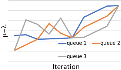
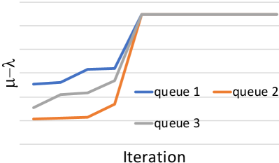
The intuition behind Proposition 3 is that BH does not waste iterations making changes that would eventually have to be reversed. Even if the worst-case complexity proven in Proposition 2 is the same as other algorithms, the actual number of iterations needed to converge is much smaller (see Sec. 9.4). The difference between BH and gradient-based algorithms is exemplified in Fig. 5, in the case of a path with three queues. Both Newton’s algorithm (left) and BH (right) converge to the same optimum solution; also, in both cases the lowest value increases from one iteration to the next. However, Newton’s algorithm could occasionally decrease the value for some of the least busy queues, and then be forced to undo those changes. BH, instead, never does so, and converges to the optimum faster.
Notice that, Proposition 3 is only guaranteed to hold under the same conditions as for Thm. 2, i.e., when the sojourn time pdfs are log-convex. However, as highlighted by our performance evaluation in Sec. 9, BH exhibits the same desirable behavior under a much wider range of conditions, including those when no closed-form expression of sojourn time distributions exists, e.g., for queues.
Finally, we remark that BH exhibits fundamental differences with respect to multi-path packet routing. First, routing protocols (including state-of-the-art QUIC implementations [50]) make their decisions based on the average latency of each route, as opposed to the full latency distribution. Second, routing protocols look at either end-to-end or next-hop latencies, while BH accounts for individual road segments and how each of them contributes to the travel times.
8 Validation Methodology
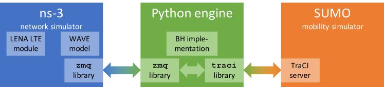
To assess its performance, we integrate BH within a complete validation environment, as represented in Fig. 6. Policies summarized by the and variables are defined by BH, which is implemented within a Python engine. Such decisions are then relayed to the ns-3 network simulator, which is in charge of simulating: (i) the network traffic generated by vehicles and by the infrastructure, and (ii) the actualizers, which, based on the most recent CAMs, implement the edge-defined policy. Specifically, for the navigation service, vehicles of flow are randomly assigned a path following the probabilities and are instructed accordingly through DENMs. For the lane-change service, within every time window (e.g., 30 seconds), the vehicles of each flow having more free space in the destination lane (detected as per [6]) are instructed through DENMs to change lane, so as to honor probabilities ’s. In the case of the lane-change service, upon receiving a DENM, vehicles engage their neighbors in a communication following the protocol in [5], to coordinate their manoeuvres and avoid collisions. In both the lane-change and the navigation cases, mobility is simulated via SUMO and vehicles traversing stretch of road are instructed to travel at speed . Based on the SUMO simulation, the position of each vehicle is then updated within ns-3.
The mobility information is relayed between ns-3 and SUMO through the Python engine and the TraCI Python library. The ns-3 simulator and the Python engine interact through the zmq message-passing framework, using the client libraries available for both Python and C++. The communication between SUMO and the Python engine, instead, takes place through the TraCI protocol.
In SUMO, flows include a mixture of different vehicle types, namely cars (SUMO class passenger, 85% of all vehicles), trucks (class truck, 10% of vehicles), and buses (class coach, 5% of vehicles). Their target speed, acceleration, and driving aggressiveness values are left to the SUMO default, subject to a global speed limit of 50 km/h, as it is common in urban areas. The simulation step size of SUMO, which also determines the frequency of position updates in ns-3, is set to 10 ms.
In ns-3, LTE (provided by the LENA module) is used for the communication between vehicles and infrastructure, while WAVE (in the default ns-3 distribution) is used for V2V communication, including that required for lane change. CAMs and DENMs are encoded as foreseen by the ETSI 302.637 standard for ITS. Upon receiving a DENM, vehicles take action immediately, which corresponds to the case of autonomous vehicles. Human reaction times, usually quantified in 1 s [41], could be easily accounted for.
9 Numerical Results
We now demonstrate how our system model and the BH algorithm can be exploited, with reference to our two applications of assisted driving, namely, lane-change and navigation. Such applications have different time and geographical scales, thus, the fact that BH is effective in both cases demonstrates its flexibility and generality.
Below, we first use a small-scale, yet representative, scenario, in order to easily visualize the parameters and variables involved in our decisions and better understand their mutual influence (Sec. 9.1). In such a scenario, we show the excellent performance of BH and highlight the impact of the path probabilities on the system performance. Then we move to larger, more complex scenarios (Sec. 9.2–Sec. 9.3). In these cases, we use BH to obtain the global policies and, as described in Sec. 8, evaluate their effect on the travel times in real-world, practical scenarios. Finally, we present some results on the convergence of BH (Sec. 9.4).
Benchmark solutions. We benchmark our BH scheme against two alternative solutions. The first is the fully-distributed solution where vehicles only communicate with neighboring vehicles (as per [5]), exploiting only local information to make lane-change decisions. More specifically, vehicles change lane if there are fewer neighbors (detected through CAMs) than in the current one. The second is a centralized solution based on the matching between flows and paths [51]. Such a solution runs the matching algorithm in [52] on a bipartite graph where: (i) vertices represent the paths and flows; (ii) edges connect each flow with the paths it can take; (iii) conflict edges [52] join the paths sharing one or more queues. The algorithm in [52] yields a near-optimal solution, matching each flow with the paths resulting in the shortest travel time, and accounting for the fact that paths may share one or more queues, leading to higher congestion.
9.1 Lane-change, small-scale scenario
We begin by considering a lane-change service in the small-scale scenario described in Fig. 1 and modeled in Fig. 3. Therein, there are two incoming flows, namely, flows 1 and 2: the former is associated with one path only, the latter with two paths. These two paths are called early and late, referring to the fact that vehicles turn north (respectively) after the first road segment (i.e., ), or after the second one (i.e., ). We set the normalized incoming rate to for both flows (rates are normalized to the arrival rate of flow 1), and the maximum normalized service rate to for all road segments, except for that, owing to the fact that vehicles therein need to slow down, has a maximum normalized service rate . Also, we set to 5 time units for both flows. In such a scenario, the best values of coincide with for all road segments, thus the decisions to make are summarized by the variable (indeed, flow 1 only has one path and ).
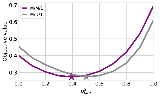
The first, high-level question we seek to answer concerns the relationship between the variable and the value of the objective function (14). Fig. 7 shows that it is advantageous to split the vehicles of flow 2 more or less evenly between its two possible paths.
The third message conveyed by Fig. 7 is about the flexibility of our approach: the purple curve is obtained by modeling road segments as queues, using the closed-form expressions in Sec. 5.1, while the gray curve is obtained by using queues. Since there is no closed-form expression of the sojourn time distribution in queues, we implemented the approximate formula presented in [53], and solved numerically integrals and convolutions. In spite of the very significant differences with respect to the case, our approach and BH work with no changes in both cases: our solution strategy does not depend on any specific service time distribution, and does not require such a distribution to have a closed-form expression.
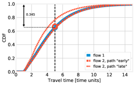
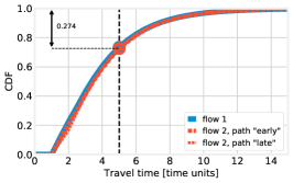
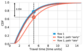
Still for the case, Fig. 8 shows the distribution of the per-path travel times, along with a graphical interpretation of the , , and quantities. Each curve corresponds to a path, and its color represents the flow each path belongs to (namely, blue: flow 1, red: flow 2). Firstly, we observe that, as the intuition would suggest, a higher value of , i.e., sending more vehicles to path late of flow 2, results in longer travel times for that path, and shorter ones for path early. Secondly, the black vertical line in all plots corresponds to the value of the target travel time ; ideally, one would like all CDFs to be at the left of such a line. The intersections between the CDFs and the vertical line represent the probability that vehicles belonging to a flow take a path whose travel time does not exceed , i.e., . Instead, the circles noted on the plots represent the flow-wise performance : as specified in (8), such a quantity is defined as a weighted sum of the values, thus, is close to when most vehicles take path early (left plot), and close to in the opposite case (right plot).
The lowest circle, and the numerical values reported in the plots, correspond to the largest value of , i.e., the value of the objective function in (14): intuitively, reducing the value of the objective function in (14) corresponds to pushing up such a circle as high as possible. Note that the flow with the highest changes for different values of : it is flow 1 in the left plot, and flow 2 in the right one. In the center plot, corresponding to the best solution as identified by both brute force and BH, all paths exhibit roughly the same travel time distribution. This is consistent with the intuition we gather from Thm. 3 and leverage on the design of the BH algorithm: similar path travel times result in better performance. Importantly, the hypothesis of Thm. 3 does not hold in this scenario – and, indeed, path travel times are not exactly the same – nonetheless, the intuition we gather from it is sill valid.
9.2 Lane-change, medium-scale scenario
We now move to a medium-scale, lane-change scenario, with three vehicular flows, numbered from 1 to 3, traveling across a three-lane road, as depicted in Fig. 9. Traffic flows originate at the beginning of one of the three lanes and can terminate at the end of any lane, not necessarily the one they started at. Since, in our model, flows must have a unique destination, we introduce a further, fictitious queue , and make all flows terminate there, as depicted in Fig. 9(bottom). While all other queues are modelled as , is an queue where the sojourn time coincides with the deterministic service time and can easily be discounted from the per-path and per-flow travel times.
In this scenario, we consider the lane-change service and translate the BH policies into instructions to vehicles, following the methodology described in Sec. 8. Note that the challenge here is not due to an obstacle on the road (which is not present any longer), but to the significant difference among the incoming flows, namely, , , . The maximum service rate of all queues is , while the target travel time is set to for all flows. Note that rate values are normalized to , while time values are normalized to .
Fig. 10(left) presents the CDF of the vehicle travel time for each flow when decisions are made by BH (solid lines), or by the distributed decision scheme [5] (dotted lines), or the bipartite-matching strategy. BH yields much shorter travel times; furthermore, the difference between the flows, which is evident when decisions are made in a distributed manner, almost disappears. The bipartite-matching strategy yields better performance than the distributed one – which, intuitively, is due to the fact that such a strategy uses global information. However, it is unable to match BH due to its inability to break flows across multiple paths, like BH does.
An explanation of the difference between BH and the distributed solution is presented in Fig. 10(center). Each marker in the plot corresponds to one of the existing paths, and its position along the x- and y-axes is given, respectively, by the average travel time over the path and the number of vehicles using it; crosses correspond to distributed decisions, circles to BH. We can observe that, when decisions are made in a distributed fashion, the usage and path travel time change considerably, and the corresponding markers are spread throughout the plot. On the contrary, with BH, the paths have travel times that are not only shorter, but also very similar to each other – hence, the corresponding markers are clustered together, and often overlapping. This is a consequence of how BH chooses the flows and paths to act upon (Line 8 and Line 9 in Alg. 1), which in turn reflects the min-max nature of objective (14): traffic is always moved from more-crowded paths to less-crowded ones.
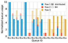
Fig. 10(right) summarizes how each queue is used by every flow. By comparing hatched bars (distributed decisions) to solid bars (BH), we observe how BH moves a more significant fraction of flow 1’s traffic away from the northernmost lane towards the center (and, also, southern) ones. Counterintuitively enough, the traffic of flow 3 is scarcely moved to the center lane (see ), which is taken by vehicles of flow 1; rather, a significant portion of flow 2 is moved to the southern lane to make room for flow 1 in the center lane. Such behaviors are unlikely to emerge as a combination of distributed decisions; instead, our comprehensive approach and the BH algorithm are able to identify and enforce them.
Fig. 10(right) also explains why, when distributed decisions are made, the travel times of the lower-rate traffic flows (2 and 3) are quite long and similar to those of flow 1 (see Fig. 10(left)). The reason is that such flows are routed through the center lane, which is also used by vehicles of flow 1, thereby increasing the congestion and travel times of all flows. It also explains how it is possible for BH to reduce the travel times for all flows, contrary to the intuition that removing congestion from one flow unavoidably means increasing it for some other. This is connected with the well-known notion that, in queuing systems, the total traffic is conserved but the sum of sojourn times is not, since sojourn times increase much faster than linearly (hyperbolically, in queues) with queue utilization.
9.3 Navigation service, large-scale scenario
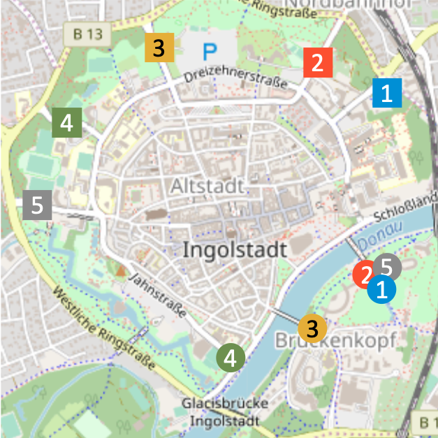
Here we still evaluate the BH performance under practical conditions, but we move to a large-scale scenario where a total of flows travel across a road topology including road segments modelled as queues, yielding paths. Both the road topology and the intensity of traffic flows are extrapolated from the real-world mobility trace in [54] (see Fig. 11), obtaining a many-to-many-to-many correspondence between flows, paths and queues.
In such a scenario, we provide a navigation service, aiming at guiding all vehicles from the origin of their trip to their destination, within their target time . In particular, we set the following normalized -values: , , , , . The source and destination of flows, as well as their intensity (i.e., the number of vehicles belonging to each of them) come from the real-world trace [54]. Notice how flows are fairly diverse in length and parts of the city to traverse: some, like flow 1 and flow 4, only concern suburban areas of the city; others, like flow 3, need to cross the city center. Similarly, some flows (e.g., flow 1 and flow 2) are more likely than others to use the same road segments.
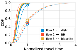
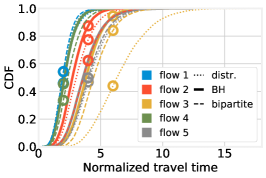
Fig. 12(left) summarizes the CDF of the travel times for each flow: solid lines correspond to decisions made with BH, while dashed lines correspond to distributed decisions made by vehicles based on shortest-path routing. Interestingly, decisions made by BH result in substantially shorter travel times for the busiest flows, namely, flow 3 (yellow lines), flow 5 (gray lines), and flow 2 (red lines). Flow 1 (blue lines) is virtually unchanged, while the least congested flow, flow 4 (green lines), experiences slightly longer travel times. As discussed earlier, BH reduces the travel times of congested flows, without increasing – or, as in this case, increasing to a very limited extent – the others. The matching-based solution yields trip time similar to BH (as both solutions employ global information) but slightly longer (as BH is able to accurately split flows across paths).
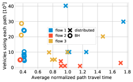
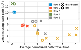
Fig. 12(center) provides more details on how such an improvement is achieved. The performance of flows 3 and 5 is improved mostly by avoiding the most crowded paths (rightmost yellow markers), and routing instead more vehicles on less-crowded ones (leftmost markers). This comes at the cost of increasing the load on some of the queues shared with flow 4 (green markers): the circle representing its only path is indeed further right than the corresponding cross. The markers of flow 1 overlap, which is consistent with the fact that, as shown in Fig. 12(left), the flow performance does not change.
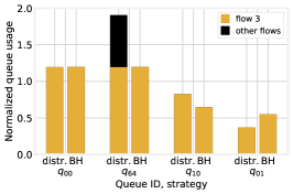
Fig. 12(right) focuses on the busiest flow (flow 3), and the queues serving the highest number of vehicles thereof. For each queue, yellow bars represent the number of vehicles of flow 3 traversing it, and black ones the number of vehicles of all other flows. From the figure, it is possible to observe two of the main ways in which BH improves flow 3’s performance. The first is clearly exemplified by queue : if a queue is heavily used by flow 3, then vehicles of other flows are directed elsewhere, thereby lowering the travel times. In other words, BH improves the travel time of the less fortunate flows (as per (14)), by preventing multiple flows from crowding the same road segments.
The second can be observed in queues and : as far as possible, BH ensures that all queues have the same load. This is again consistent with the insight provided by Thm. 3, that similar loads are associated with shorter travel times.
Summary. As reported in Tab. I and Tab. II, the BH algorithm can consistently outperform its alternatives, in terms of vehicle trip times and queue occupancy. As shown in Tab. I, the average trip time drops by 66% in the lane-changing application (medium scenario), and by 20% in the navigation one (large scenario).
This highlights the validity of the BH approach, which can split flow across paths (unlike the bipartite-matching one), while at the same time accounting for global information and the potentially far-reaching consequences of local decisions (unlike the distributed approach).
9.4 Convergence speed
Last, we focus on the convergence of BH and compare it against the iterative algorithm BFGS [48], as implemented in the scipy library. Tab. III reports the convergence speed (expressed in number of objective function evaluations) of the two algorithms. BH consistently requires fewer iterations than BFGS to converge, which confirms our intuition that leveraging problem-specific knowledge and insights results in faster convergence. It is also interesting to notice how convergence in the medium-scale scenario takes longer than in the large-scale one, owing to the higher number of paths (hence, of decisions to make) therein.
| Scenario | BH | bipartite | distributed |
|---|---|---|---|
| Medium | 4.01 | 4.71 | 11.9 |
| Large | 30.1 | 34.3 | 37.6 |
| Scenario | BH | bipartite | distributed |
|---|---|---|---|
| Medium | 0.42 | 0.51 | 1.27 |
| Large | 0.37 | 0.42 | 0.45 |
| Metric | Scenario | BH | BFGS |
|---|---|---|---|
| Convergence speed [no. of objective evaluations] | Small | 210 | 613 |
| Medium | 843 | 1039 | |
| Large | 512 | 797 |
10 Conclusions
We addressed the problem of providing connected vehicles and their drivers with effective assistance services. We proposed an edge-based system including two logical entities, namely, policy maker and actualizer. The former leverages global information, in order to make effective vehicle flow policies, while the latter translates such policies into instructions that the single vehicles should enact in the short time span. We modeled the system under study by leveraging a queue-based representation of the road topology and vehicles’ behavior, which allows for formulating an optimization problem that minimizes the vehicles’ travel time. Then, motivated by the problem complexity and the need to address large-scale scenarios, we presented a swift iterative algorithm providing optimal policies in linear time. We assessed the performance of the proposed approach through a full-fledged, realistic simulation framework, showing the benefits of our solution in terms of vehicles’ travel times with respect to traditional distributed approaches.
References
- [1] World Health Organization. Global status report on road safety.
- [2] M. Zhou, X. Qu, and S. Jin, “On the impact of cooperative autonomous vehicles in improving freeway merging: a modified intelligent driver model-based approach,” IEEE Trans. on ITS, 2016.
- [3] J. Lehoczky, “Traffic intersection control and zero-switch queues under conditions of markov chain dependence input,” Journal of Applied Probability, 1972.
- [4] M. C. Dunne, “Traffic delay at a signalized intersection with binomial arrivals,” INFORMS Transportation Science, 1967.
- [5] L. Hobert, A. Festag, I. Llatser, L. Altomare, F. Visintainer, and A. Kovacs, “Enhancements of v2x communication in support of cooperative autonomous driving,” IEEE Comm. Mag., 2015.
- [6] M. Fallgren, M. Dillinger, J. Alonso-Zarate, M. Boban, T. Abbas, K. Manolakis, T. Mahmoodi, T. Svensson, A. Laya, and R. Vilalta, “Fifth-generation technologies for the connected car: Capable systems for vehicle-to-anything communications,” IEEE Veh. Tech. Mag., 2018.
- [7] A. de la Oliva et al., “5g-transformer: Slicing and orchestrating transport networks for industry verticals,” IEEE Comm. Mag., 2018.
- [8] ETSI, “ETSI 103 299 - v2.1.1,” Tech. Rep., 2019.
- [9] F. Malandrino, C. F. Chiasserini, and G. M. Dell’Area, “An Edge-powered Approach to Assisted Driving,” in IEEE Globecom, 2020.
- [10] ETSI. MEC Deployments in 4G and Evolution Towards 5G.
- [11] A. Moubayed, A. Shami, P. Heidari, A. Larabi, and R. Brunner, “Edge-enabled V2X Service Placement for Intelligent Transportation Systems,” IEEE Transactions on Mobile Computing, 2020.
- [12] ——, “Cost-optimal v2x service placement in distributed cloud/edge environment,” in IEEE WiMob, 2020.
- [13] Q.-H. Nguyen, M. Morold, K. David, and F. Dressler, “Car-to-pedestrian communication with mec-support for adaptive safety of vulnerable road users,” Computer Communications, 2020.
- [14] Q. Nguyen, M. Morold, K. David, and F. Dressler, “Adaptive Safety Context Information for Vulnerable Road Users with MEC Support,” in IEEE/IFIP WONS, 2019.
- [15] T. Van Woensel and N. Vandaele, “Modeling traffic flows with queueing models: A review,” Asia-Pacific Journal of Operational Research (APJOR), 2007.
- [16] M. Khabazian and M. K. M. Ali, “A performance modeling of connectivity in vehicular ad hoc networks,” IEEE Transactions on Vehicular Technology, 2008.
- [17] M. J. Khabbaz, W. F. Fawaz, and C. M. Assi, “A simple free-flow traffic model for vehicular intermittently connected networks,” IEEE Transactions on Intelligent Transportation Systems, 2012.
- [18] G. Gomes, “A framework for hybrid simulation of transportation networks,” Journal of Simulation, vol. 0, no. 0, pp. 1–16, 2020.
- [19] A. S. Alfa and M. F. Neuts, “Modelling vehicular traffic using the discrete time markovian arrival process,” INFORMS Transportation Science, 1995.
- [20] D. Heidemann, “A queueing theory approach to speed-flow-density relationships,” in International Symposium on Transportation and Traffic Theory, 1996.
- [21] T. Van Woensel and N. Vandaele, “Empirical validation of a queueing approach to uninterrupted traffic flows,” Springer 4OR, 2006.
- [22] Z. Zhou, H. Yu, C. Xu, Z. Chang, S. Mumtaz, and J. Rodriguez, “Begin: Big data enabled energy-efficient vehicular edge computing,” IEEE Comm. Mag., 2018.
- [23] Z. Ning, J. Huang, and X. Wang, “Vehicular fog computing: Enabling real-time traffic management for smart cities,” IEEE Wireless Comm., 2019.
- [24] L. Zhao, F. Wang, K. Zheng, and T. Riihonen, “Joint optimization of communication and traffic efficiency in vehicular networks,” IEEE Trans. on Veh. Tech., 2018.
- [25] S. Mukhopadhyay, M. Pramod, and A. Kumar, “Approximate mean delay analysis for a signalized intersection with indisciplined traffic,” IEEE transactions on intelligent transportation systems, vol. 18, no. 10, pp. 2750–2762, 2017.
- [26] G. Comert and M. Cetin, “Analytical evaluation of the error in queue length estimation at traffic signals from probe vehicle data,” IEEE Trans. on ITS, 2011.
- [27] C. O. Pisano, “Mitigating network congestion: analytical models, optimization methods and their applications,” Ph.D. dissertation, EPFL, 2010.
- [28] C. Borgiattino, F. Malandrino, C. Casetti, and C.-F. Chiasserini, “Modelling realistic vehicle traffic flows,” in IEEE SECON VCSC Workshop, 2012.
- [29] R. Timmerman and M. A. Boon, “Platoon forming algorithms for intelligent street intersections,” in Mathematics Applied in Transport and Traffic Systems, 2019.
- [30] E. Harahap, D. Darmawan, Y. Fajar, R. Ceha, and A. Rachmiatie, “Modeling and simulation of queue waiting time at traffic light intersection,” in IOP Journal of Physics: Conference Series, 2019.
- [31] V. Kanagaraj, K. K. Srinivasan, and R. Sivanandan, “Modeling vehicular merging behavior under heterogeneous traffic conditions,” SAGE Transportation Research Record, 2010.
- [32] Z. Wang, L. Kulik, and K. Ramamohanarao, “Proactive traffic merging strategies for sensor-enabled cars,” in Automotive informatics and communicative systems: Principles in vehicular networks and data exchange, 2009.
- [33] V. Milanés, J. Godoy, J. Villagrá, and J. Pérez, “Automated on-ramp merging system for congested traffic situations,” IEEE Trans. on ITS, 2010.
- [34] T. Abbas, L. Bernado, A. Thiel, C. Mecklenbrauker, and F. Tufvesson, “Radio channel properties for vehicular communication: Merging lanes versus urban intersections,” IEEE Veh. Tech. Mag., 2013.
- [35] A. T. Hojati, L. Ferreira, S. Washington, and P. Charles, “Hazard based models for freeway traffic incident duration,” Accident Analysis & Prevention, 2013.
- [36] M. Baykal-Gürsoy, W. Xiao, and K. Ozbay, “Modeling traffic flow interrupted by incidents,” European Journal of Operational Research, 2009.
- [37] Z. Duan, “Emergency modeling in transportation via queuing and game theory,” Ph.D. dissertation, Rutgers University-Graduate School-New Brunswick, 2013.
- [38] L. Bi, C. Wang, X. Yang, M. Wang, and Y. Liu, “Detecting driver normal and emergency lane-changing intentions with queuing network-based driver models,” International Journal of Human-Computer Interaction, 2015.
- [39] S. Lee, M. Younis, A. Murali, and M. Lee, “Dynamic local vehicular flow optimization using real-time traffic conditions at multiple road intersections,” IEEE Access, 2019.
- [40] M. Azizian, S. Cherkaoui, and A. Hafid, “An optimized flow allocation in vehicular cloud,” IEEE Access, 2016.
- [41] M. Malinverno, G. Avino, C. Casetti, C. F. Chiasserini, F. Malandrino, and S. Scarpina, “Edge-based collision avoidance for vehicles and vulnerable users: an architecture based on MEC,” IEEE Vehicular Technology Magazine, 2020.
- [42] H. Zhu, R. Lu, X. Shen, and X. Lin, “Security in service-oriented vehicular networks,” IEEE Wireless Communications, 2009.
- [43] E. G. Coffman, Jr., R. R. Muntz, and H. Trotter, “Waiting time distributions for processor-sharing systems,” Journal of the ACM, 1970.
- [44] H. Kung and D. Tong, “Fast algorithms for partial fraction decomposition,” SIAM Journal on Computing, 1977.
- [45] J. Medhi, Stochastic models in queueing theory. Elsevier, 2002.
- [46] H. Tuy, “Monotonic optimization: Problems and solution approaches,” SIAM Journal on Optimization, 2000.
- [47] J. F. C. Kingman, “A convexity property of positive matrices,” The Quarterly Journal of Mathematics, 1961.
- [48] R. Fletcher, “A new approach to variable metric algorithms,” Computer Journal, 1970.
- [49] L. Bottou, “Stochastic gradient descent tricks,” in Neural networks: Tricks of the trade. Springer, 2012.
- [50] Q. De Coninck and O. Bonaventure, “Multipath QUIC: Design and evaluation,” in ACM CoNEXT, 2017.
- [51] A. A. Bertossi, P. Carraresi, and G. Gallo, “On some matching problems arising in vehicle scheduling models,” Wiley Networks, 1987.
- [52] C. Chen, L. Zheng, V. Srinivasan, A. Thomo, K. Wu, and A. Sukow, “Conflict-aware weighted bipartite b-matching and its application to e-commerce,” IEEE Transactions on Knowledge and Data Engineering, 2016.
- [53] V. Iversen and L. Staalhagen, “Waiting time distribution in M/D/1 queueing systems,” IEEE Electronics Letters, 2000.
- [54] C. Sommer, D. Eckhoff, and F. Dressler, “IVC in cities: signal attenuation by buildings and how parked cars can improve the situation,” IEEE Trans. on Mobile Computing, 2014.