Effective Carrier Sensing in CSMA Networks under Cumulative Interference
Abstract
This paper proposes and investigates the concept of a safe carrier-sensing range that can guarantee interference-safe (also termed hidden-node-free) transmissions in CSMA networks under the cumulative interference model. Compared with the safe carrier-sensing range under the commonly assumed but less realistic pairwise interference model, we show that the safe carrier-sensing range required under the cumulative interference model is larger by a constant multiplicative factor. For example, if the SINR requirement is and the path-loss exponent is , the factor is . The concept of a safe carrier-sensing range, although amenable to elegant analytical results, is inherently not compatible with the conventional power-threshold carrier-sensing mechanism (e.g., that used in IEEE 802.11). Specifically, the absolute power sensed by a node in the conventional mechanism does not contain enough information for it to derive its distances from other concurrent transmitter nodes. We show that, fortunately, a carrier-sensing mechanism called Incremental-Power Carrier-Sensing (IPCS) can realize the carrier-sensing range concept in a simple way. Instead of monitoring the absolute detected power, the IPCS mechanism monitors every increment in the detected power. This means that IPCS can separate the detected power of every concurrent transmitter, and map the power profile to the required distance information. Our extensive simulation results indicate that IPCS can boost spatial reuse and network throughput by more than relative to the conventional carrier-sensing mechanism. Last but not least, IPCS not only allows us to implement our safe carrier-sensing range, it also ties up a loose end in many other prior theoretical works that implicitly assume the use of a carrier-sensing range (safe or otherwise) without an explicit design to realize it.
Index Terms:
carrier-sensing range, cumulative interference model, CSMA, WiFi, IEEE 802.11, SINR constraints, spatial reuse.I Introduction and Overview
Due to the broadcast nature of wireless channels, signals transmitted over wireless links can mutually interfere with each other. How to optimize spatial reuse and network throughput under such mutual interferences has been an intensely studied issue in wireless networking. In particular, it is desirable to allow as many links as possible to transmit together in an interference-safe (or collision-free) manner. The problem of interference-safe transmissions under the coordination of a centralized TDMA (Time-Division Multiple-Access) scheduler has been well studied (e.g., see [1, 2, 3, 4, 5, 6]). Less well understood is the issue of interference-safe transmissions under the coordination of a distributed scheduling protocol.
The CSMA (Carrier-Sense Multiple-Access) protocol, such as IEEE 802.11, is the most widely adopted distributed scheduling protocol in practice. As the growth of 802.11 network deployments continues unabated, we are witnessing an increasing level of mutual interference among transmissions in such networks. It is critical to establish a rigorous conceptual framework upon which effective solutions to interference-safe transmissions can be constructed.
Within this context, this paper has three major contributions listed as follows (more detailed overview is given in the succeeding paragraphs):
-
1.
We propose the concept of a safe carrier-sensing range that can guarantee interference-safe transmissions in CSMA networks under the cumulative interference model.
-
2.
We show that the concept is implementable using a very simple Incremental-Power Carrier-Sensing (IPCS) mechanism.
-
3.
We demonstrate that implementation of safe carrier-sensing range under IPCS can significantly improve spatial reuse and network throughput as compared to the conventional absolute-power carrier sensing mechanism.
Regarding 1), this paper considers the cumulative interference model (also termed physical interference model in [7]), in which the interference at a receiver node consists of the cumulative power received from all the other nodes that are currently transmitting (except its own transmitter). This model is known to be more practical and much more difficult to analyze than the widely studied pairwise interference model (also termed the protocol interference model in [7]) in the literature. Under the cumulative interference model, a set of simultaneously transmitting links are said to be interference-safe if the SINRs (Signal-to-Interference-plus-Noise Ratios) at the receivers of all these links are above a threshold. Given a set of links in the network, there are many subsets of links, , that are interference-safe. The set of all such subsets constitutes the feasible interference-safe state space. For centralized TDMA, all subsets are available for scheduling, and a TDMA schedule is basically a sequence where each . For CSMA, because of the random and distributed nature of the carrier-sensing operations by individual nodes, the simultaneously transmitting links may or may not belong to . Let . The CSMA network is said to be interference-safe if . This is also the condition for the so-called hidden-node free operation [8]. However, this issue was studied under the context of an idealized pairwise interference model [8] rather than the practical cumulative interference model of interest here. In this paper, we show that if the carrier-sensing mechanism can guarantee that the distance between every pair of transmitters is separated by a safe carrier-sensing range, then can be guaranteed and the CSMA network is interference-safe even under a cumulative interference model. We believe that the safe carrier-sensing range established in this paper is a tight upperbound and achieves good spatial reuse. Another issue is how to implement the concept of safe carrier-sensing range in practice.
This brings us to 2) above. In traditional carrier sensing based on power threshold (e.g., that of the basic mode in IEEE 802.11), the absolute power received is being monitored. This power consists of the sum total of powers received from all the other transmitters. It is impossible to infer from this absolute power the exact separation of the node from each of the other transmitters. This leads to subpar spatial reuse. Fortunately, we show that a simple mechanism that monitors the incremental power changes over time, IPCS, will enable us to map the power profile to the required distance information. We believe that this contribution, although simple, is significant in that it shows that the theoretical concept of safe carrier-sensing range can be implemented rather easily in practice. It also ties up a loose end in many other prior theoretical works that implicitly assume the use of a carrier-sensing range (safe or otherwise) without an explicit design to realize it. That is, IPCS can be used to implement the required carrier-sensing range in these works, not just our safe carrier-sensing range here. Without IPCS, and using only the conventional carrier-sensing mechanism, the results in these prior works would have been overly optimistic. Given the implementability of safe carrier-sensing range, the next issue is how tight the simultaneously transmitting nodes can be packed.
This brings us to 3) above. In the conventional carrier sensing mechanism, in order that the detected absolute power is below the carrier-sensing power threshold, the separation between a newly active transmitter and other existing active transmitters must increase progressively as the number of concurrent transmissions increases. That is, the cost of ensuring interference-safe transmissions becomes progressively higher and higher in the “packing process”. This reduces spatial reuse and the overall network throughput. Fortunately, with IPCS, the required separation between any pair of active transmitters remains constant as the safe carrier-sensing range which is independent of the number of concurrent transmissions. Indeed, our simulation results indicate that compared to the conventional carrier-sensing mechanism, IPCS mechanism improves the spatial reuse and the network throughput by more than .
I-A Related Work
In the literature, most studies on carrier sensing (e.g., [10, 8, 13, 11, 9, 12]) are based on the pairwise interference model. For a link under the pairwise interference model, the interferences from the other links are considered one by one. If the interference from each of the other links on the link concerned does not cause a collision, then it is assumed that there is no collision overall. Ref. [8] established the carrier-sensing range required to prevent hidden-node collisions in CSMA networks under the pairwise interference model. The resulting carrier-sensing range is too optimistic and can not eliminate hidden-node collisions if the more accurate cumulative interference model is adopted instead.
A number of recent papers studied the CSMA networks under the cumulative interference model (e.g., [14, 15, 16, 17]). An earlier unpublished technical report of ours [17] derived the safe carrier-sensing range under the cumulative interference model. The technical report, however, did not include the IPCS realization presented in this paper. Neither did Ref. [14, 15, 16] address the implementation of a carrier-sensing range based on power detection. Ref. [14] studied the asymptotic capacity of large-scale CSMA networks with hidden-node-free designs. The focus of [14] is on “order” result rather than “tight” result. For example, if and , the safe carrier-sensing range derived in [14] is . In this paper, we show that setting the safe carrier-sensing range to is enough to prevent hidden-node collisions.
The authors in [15, 16] attempted to improve spatial reuse and capacity by tuning the transmit power and the carrier-sensing range. Although the cumulative interference model is considered in [15, 16], spatial reuse and capacity are analyzed based on carrier-sensing range. In particular, they assumed that the transmitters of concurrent transmission links can be uniformly packed in the network. As discussed in this paper, such uniform packing can not be realized using the current 802.11 carrier-sensing mechanism. Therefore, the results in [15, 16] are overly optimistic without an appropriate carrier-sensing mechanism. IPCS fills this gap so that the theoretical results of [15, 16] remain valid. We summarize the key related models and results in the literature in Table I***This paper focuses on the incremental-power carrier-sensing (IPCS) mechanism under the cumulative interference model. But IPCS proposed in this paper can also deal with the pairwise interference model..
| Interference Models | Pairwise Interference Model | Cumulative Interference Model |
|---|---|---|
| Absolute power carrier sensing | many (e.g., [8, 10]) | [15, 16] |
| Incremental power carrier sensing | This paper | This paper |
The rest of this paper is organized as follows. Section II presents the cumulative interference model and the carrier sensing mechanism in the current 802.11 protocol. Section III derives the safe carrier-sensing range that successfully prevents the hidden-node collisions under the cumulative interference model. Section IV presents the IPCS mechanism. Section V evaluates the performance of IPCS in terms of spatial reuse and network throughput. Section VI concludes this paper.
II System Model
II-A Cumulative Interference Model
We represent links in a wireless network by a set of distinct and directed transmitter-receiver pairs . Let and denote the set of transmitter nodes and the set of receiver nodes, respectively. A receiver decodes its signal successfully if and only if the received Signal-to-Interference-plus-Noise Ratio (SINR) is above a certain threshold. We adopt the cumulative interference model, where the interference is the sum of the received powers from all transmitters except its own transmitter. We assume that radio signal propagation follows the log-distance path model with path loss exponent . The path gain from transmitter to receiver follows a geometric model:
where is the Euclidean distance between nodes and .
In 802.11, each packet transmission on a link consists of a DATA frame in the forward direction (from to ) followed by an ACK frame in the reverse direction (from to ). The packet transmission is said to be successful if and only if both the DATA frame and the ACK frame are received correctly. Let () denote the set of links that transmit concurrently with the DATA (ACK) frame on link . Under the cumulative interference model, a successful transmission on link needs to satisfy the following conditions:
| (1) |
and
| (2) |
where is the transmit power, is the average noise power, and is the SINR threshold for correct reception. We assume that all nodes in the network use the same transmit power and adopt the same SINR threshold . For a link in or , represents the sender of link , which can be either or . This is because either DATA or ACK transmission on link will cause interference to link .
II-B Existing Carrier Sensing Mechanism in 802.11
If there exists a link such that not both (1) and (2) are satisfied, this means there is collision in the network. In 802.11, carrier sensing is designed to prevent collision due to simultaneous transmissions that cause the violation of either (1) or (2). In this paper, we assume carrier sensing by energy detection. Consider a link . If transmitter senses a power that exceeds a power threshold , i.e.,
| (3) |
then will not transmit and its backoff countdown process will be frozen. This will prevent the DATA frame transmission on .
In most studies of 802.11 networks, the concept of a carrier-sensing range is introduced. The carrier-sensing range is mapped from the carrier-sensing power threshold :
Consider two links, and . If the distance between transmitters and is no less than the carrier-sensing range, i.e.,
| (4) |
then and can not carrier sense each other, and thus can initiate concurrent transmissions between them. The pairwise relationship can be generalized to a set of links . If the condition in (4) is satisfied by all pairs of transmitters in set , then all links in can transmit concurrently.
Setting an appropriate carrier-sensing range is crucial to the performance of 802.11 networks. If is too large, spatial reuse will be unnecessarily limited. If is not large enough, then hidden-node collisions may occur. The underlying cause of hidden-node collisions are as follows. A number of transmitters transmit simultaneously because condition (4) is satisfied by all pairs of the transmitters. However, there is at least one of the links does not satisfy either (1) or (2). As a result, collisions happen and the carrier sensing mechanism is said to have failed in preventing such collisions.
We now define a safe carrier-sensing range that always prevents the hidden-node collisions in 802.11 networks under the cumulative interference model.
Definition 1 (Safe-)
For analysis simplicity, we assume that the background noise power is small compared with interference and thus can be ignored. We will consider Signal-to-Interference Ratio (SIR) instead of SINR.
III Safe Carrier-sensing Range under Cumulative Interference Model
In this section, we derive a sufficient threshold for Safe-. When discussing the hidden-node free design [8], it is required that the receivers are operated with the “RS (Re-Start) mode” (see Appendix A for details). In the following discussion, we also make the same assumption.
Ref. [8] studied the safe carrier-sensing range under the pairwise interference model. The threshold is given as follows:
| (5) |
where is the maximum link length in the network. However, the pairwise interference model does not take into account the cumulative nature of interferences from other links. The threshold given in (5) is overly optimistic and not large enough to prevent hidden-node collisions under the cumulative interference model, as illustrated by the three-link example in Fig. 1.
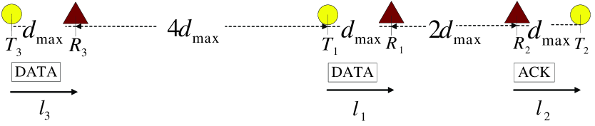
In Fig. 1, suppose that the SIR requirement and the path-loss exponent . According to (5), it is enough to set the carrier-sensing range as and the carrier sensing power threshold . In Fig. 1, there are three links: , , and with the same link length . The distance equals and the distance equals . Since the distance , from (II-B), we find that and can simultaneously initiate transmissions since they can not carrier sense each other. We can verify that the SIR requirements of both DATA and ACK transmissions on and are satisfied. This means and can indeed successfully transmit simultaneously.
Suppose that wants to initiate a transmission when is sending a DATA frame to and is sending an ACK frame to . Transmitter senses a power given by
This means that can not sense the transmissions on and , and can initiate a DATA transmission. However, when all these three links are active simultaneously, the SIR at is
This means the cumulative interference powers from and will corrupt the DATA transmission on due to the insufficient SIR at . This example shows that setting the carrier-sensing range as in (5) is not sufficient to prevent collisions under the cumulative interference model.
We next establish a threshold for Safe- so that the system will remain safe under cumulative interference.
Theorem 1
The setting
| (6) |
where
| (7) |
is sufficient to ensure interference-safe transmissions under the cumulative interference model.
Proof:
The proof is given in Appendix B. ∎
Condition (6) provides a sufficiently large carrier-sensing range that prevents the hidden-node collisions in CSMA networks. Therefore, there is no need to set a larger than the value given in (6).
Let us compare Safe- with Safe- with different values of and . For example, if and , which are typical for wireless communications,
Compared with Safe-, Safe- needs to be increased by a factor of to ensure successful transmissions under the cumulative interference model.
Given a fixed path-loss exponent , both Safe- and Safe- increase in the SIR requirement . This is because the separation among links must be enlarged to meet a larger SIR target. For example, if , we have
The ratio of Safe- to Safe- is
which is an increasing function of , and converges to a constant as goes to infinity:
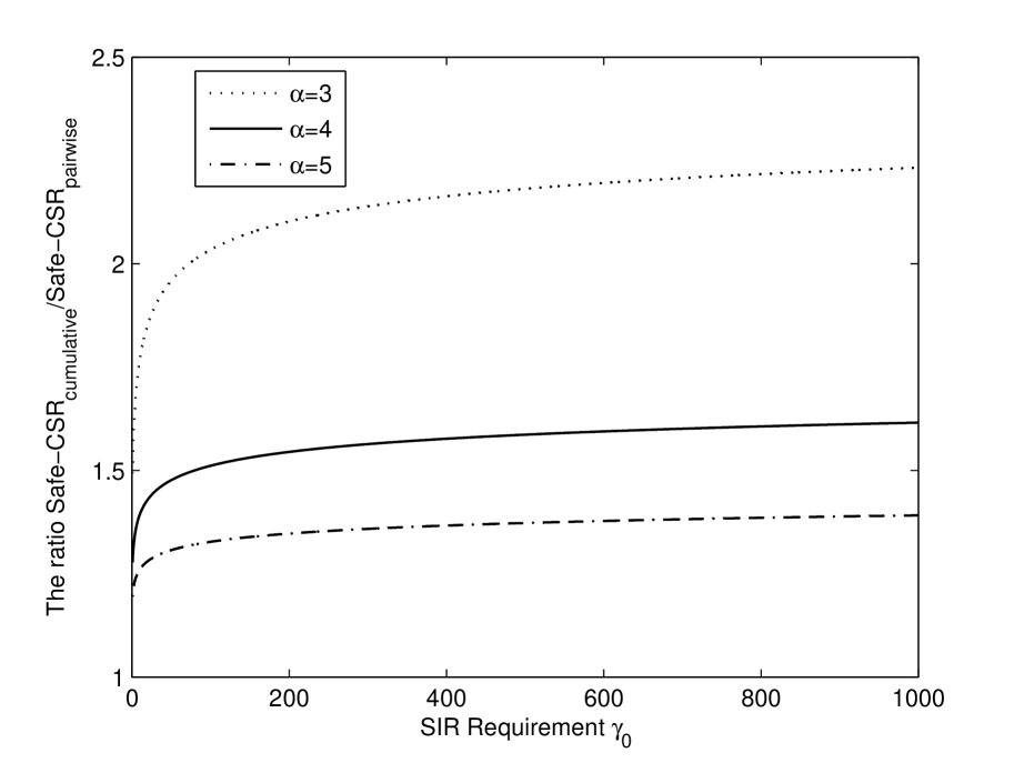
Fig. 2 shows the ratio as a function of the SIR requirements . Different curves represent different choices of the path-loss exponent . The ratio increases when increases or decreases. For each choice of , the ratio converges to a constant as goes to infinity. This shows that, compared with the pairwise interference model, the safe carrier-sensing range under the cumulative interference model will not increase arbitrarily.
IV A Novel Carrier Sensing Mechanism
We now discuss the implementation of Safe-. We first describe the difficulty of implementing the safe carrier-sensing range in (6) using the existing physical carrier-sensing mechanism in the current 802.11 protocol. Then, we propose a new Incremental-Power Carrier-Sensing (IPCS) mechanism to resolve this implementation issue.
IV-A Limitation of Conventional Carrier-Sensing Mechanism
In the current 802.11 MAC protocol, given the safe carrier-sensing range Safe-, the carrier-sensing power threshold is set as
| (8) |
Before transmitting, a transmitter compares the power it senses, , with the power threshold . A key disadvantage of this approach is that is a cumulative power from all the other nodes that are concurrently transmitting. The cumulative nature makes it impossible to tell whether is from one particular nearby transmitter or a group of far-off transmitters [18]. This reduces spatial reuse, as illustrated by the example in Fig. 3.
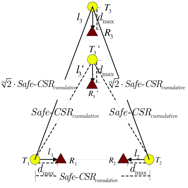
There are four links in Fig. 3, with Safe- set as in (6). In Fig. 3, the distance is equal to Safe-. From (II-B), we find that and can not carrier sense each other, thus they can transmit simultaneously.
First, consider the location requirement of the third link that can have a concurrent transmission with both and , assuming that each transmitter can perfectly differentiate the distances from the other transmitters. Suppose that the third link is located on the middle line between and . Based on the carrier-sensing range analysis, the requirements are and . So the third link can be located in the position of , shown in Fig. 3. Furthermore, as the number of links increases, a tight packing of the concurrent transmitters will result in a regular equilateral triangle packing with side length Safe-. The “consumed area” of each transmitter is a constant given by .
Now, let us consider the location requirement of the third link under the carrier-sensing mechanism of the current 802.11 protocol. In order to have concurrent transmissions with both and , the cumulative power sensed by due to transmissions of both links and should be no larger than , i.e.,
where is given in equation (8). So the minimum distance requirement on and is
as shown in Fig. 3. Since is always greater than , the requirement of the separation between transmitters is increased from (i.e., ) to (i.e., and ). The requirement on the separation between transmitters will increase progressively as the number of concurrent links increases, and the corresponding packing of transmitters will be more and more sparse. As a result, spatial reuse is reduced as the number of links increases.
Another thing to notice is that the order of the transmissions of links also affects spatial reuse in the conventional carrier-sensing mechanism. Consider the three links, , and in Fig. 3 again. If the sequence of transmissions is , as discussed above, , and sense a power no greater than , and thus , and can be active simultaneously. If the sequence of transmissions on these links is , however, both and sense a power no larger than . But the cumulative power sensed by in this case is
Therefore, will sense the channel busy and will not initiate the transmission on . The spatial reuse is unnecessarily reduced because there would have been no collisions had decide to transmit888This corresponds to the exposed-node phenomenon..
IV-B Incremental-Power Carrier-Sensing (IPCS) Mechanism
We propose an enhanced physical carrier-sensing mechanism called Incremental-Power Carrier-Sensing (IPCS) to solve the issues identified in section IV-A. Specifically, the IPCS mechanism can implement the safe carrier-sensing range accurately by separating the detected powers from multiple concurrent transmitters.
There are two fundamental causes for collisions in a CSMA network. Besides hidden nodes, collisions can also happen when the backoff mechanisms of two transmitters count down to zero simultaneously, causing them to transmit together. Note that for the latter, each of the two transmitters is not aware that the other transmitter will begin transmission at the same time. Based on the power that it detects, it could perfectly be safe for it to transmit together with the existing active transmitters, only if the other transmitter did not decide to join in at the same time. There is no way that the carrier-sensing mechanism can prevent this kind of collisions. This paper addresses the hidden-node phenomenon only. To isolate the second kind of collisions, we will assume in the following discussion of IPCS that no two transmitters will transmit simultaneous333Collisions due to simultaneous countdown-to-zero can be tackled by an exponential backoff mechanism in which the transmission probability of each node is adjusted in a dynamic way based on the busyness of the network. In WiFi, for example, the countdown window is doubled after each collision. The probability of this kind of collisions can be made small with a proper design of the backoff mechanism. Conceptually, we could imagine the random variable associated with backoff countdown to be continuous rather than discrete, which means that the starting/ending of one link’s transmission will coincide with the starting/ending of another link’s transmission with zero probability.
The key idea of IPCS is to utilize the whole carrier-sensing power history, not just the carrier-sensing power at one particular time. In CSMA networks, each transmitter carrier senses the channel except during the time when it transmits DATA or receives ACK. The power being sensed increases if a link starts to transmit, and decreases if a link finishes transmission. As a result, the power sensed by transmitter , denoted by , is a continuous function of time .
In IPCS, instead of checking the absolute power sensed at time , the transmitter checks increments of power in the past up to time . If the packet duration (including both DATA and ACK frames and the SIFS in between) is a constant for all links, then it suffices to check the power increments during the time window 444This assumption is used to simplify explanation only. In general, we could check a time window sufficiently large to cover the maximum packet size among all links.. Let denote the time instances when the power being sensed changes, and denote the corresponding increments, respectively. In IPCS, transmitter will decide the channel to be idle at time if the following conditions are met:
| (9) |
where is the carrier-sensing power threshold determined according to ; otherwise, the channel is deemed to be busy. Since is negative if a link stops transmission at some time , we only need to check the instances where the power increments are positive.
By checking every increment in the detected power, can separate the powers from all concurrent transmitters, and can map the power profile to the required distance information. In this way, IPCS can ensure the separations between all transmitters are tight in accordance with Theorem 1.
Theorem 2
If the carrier-sensing power threshold in the IPCS mechanism is set as:
| (10) |
where is the safe carrier-sensing range in (6), then it is sufficient to prevent hidden-node collisions under the cumulative interference model.
Proof:
The proof is given in Appendix C. ∎
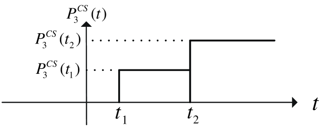
Let us use Fig. 3 again to show how IPCS can implement the safe carrier-sensing range successfully. We set the carrier-sensing power threshold as in (10). We will show that the location requirement of the third link under IPCS is the same as indicated by the safe carrier-sensing range (location in Fig. 3). The transmitter of the third link will only initiate its transmission when it senses the channel to be idle. Its carrier-sensed power is shown in Fig. 4. Without loss of generality, suppose that link starts transmission before . The third transmitter detects two increments in its carrier-sensed power at time instances and which are due to the transmissions of and , respectively. In the IPCS mechanism, the third transmitter will believe that the channel is idle (i.e., it can start a new transmission) if the following is true:
| (11) |
Substituting in (10) to (11), we find that the requirements in (11) are equivalent to the following distance requirements:
So the third link can be located at the position of , as shown in Fig. 3, instead of far away at the location of as in the conventional carrier-sensing mechanism.
Compared with the conventional carrier-sensing mechanism, the advantages of IPCS are
-
1.
IPCS is a pairwise carrier-sensing mechanism. In the IPCS mechanism, the power from each and every concurrent link is checked individually. This is equivalent to checking the separation between every pair of concurrent transmission links. With IPCS, all the analyses based on the concept of a carrier-sensing range remain valid.
-
2.
IPCS improves spatial reuse and network throughput. In the conventional carrier-sensing mechanism, the link separation requirement increases as the number of concurrent links increases. In IPCS, however, the link separation requirement remains the same. Furthermore, because IPCS is a pairwise mechanism, the order of the transmissions of links will not affect the spatial reuse.
V Simulations Results
We perform simulations to evaluate the relative performance of IPCS and conventional Carrier Sensing (CS). In our simulations, the nodes are located within in a square area of . The locations of the transmitters are generated according to a Poisson point process. The length of a link is uniformly distributed between and meters. More specifically, the receiver associated with a transmitter is randomly located between the two concentric circles of radii and centered on the transmitter. We study the system performance under different link densities by varying the number of links in the square from to in our simulations.
The simulations are carried out based on the 802.11b protocol. The common physical layer link rate is . The packet size is Bytes. The minimum and maximum backoff window and are 31 and 1023, respectively. The slot time is . The SIFS and DIFS are and , respectively. The transmit power is set as . The path-loss exponent is , the SIR requirement is , and the corresponding Safe- equals based on (6). That is, the carrier-sensing power threshold .
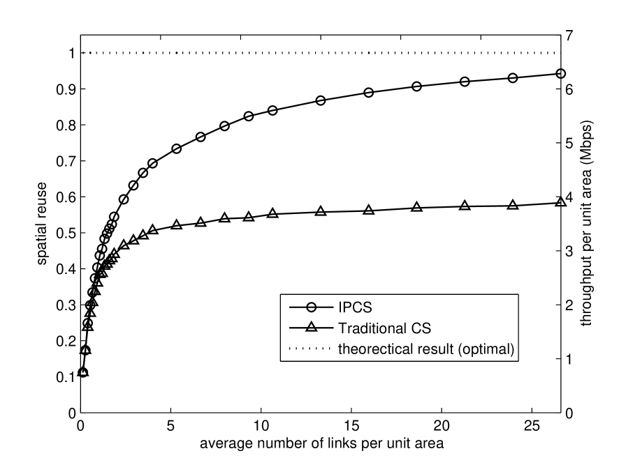
In Fig. 5, we plot spatial reuse and network throughput under IPCS and the conventional CS mechanisms. Simulation results show that network throughput is proportional to spatial reuse. So we plot these two results in the same figure. We define a “unit area” as the “consumed area” of each “active” transmitter under the tightest packing. Given Safe-, according to the carrier-sensing range analysis, the “unit area” is Safe-. The x-axis is the average number of links (i.e., all links, including active and inactive links) per unit area as we vary the total number of links in the whole square. That is, the x-axis corresponds to the link density of the network. The left y-axis is the spatial reuse, or the average “active” link density in the network. The optimal value of the spatial reuse is , which is shown as a dashed line in Fig. 5. The right y-axis is the throughput per unit area.
It is clear from Fig. 5 that IPCS outperforms the conventional CS. The improvement becomes more significant when the network becomes denser. At the densest point in the figure, spatial reuses under IPCS and conventional CS are and , respectively. The network throughputs per unit area are and , respectively. Using conventional CS as the base line, the IPCS improves spatial reuse and network throughput by more than .
Under the conventional CS, in order to make sure the cumulative detected power is no larger than the power threshold , the packing of concurrent transmission links will become more and more sparse as additional number of links attempt to transmit. Under IPCS, this does not occur. As a result, the improvement in spatial reuse is more significant as the network becomes denser.
We also find that when the network becomes denser and denser, spatial reuse under IPCS becomes very close to the theoretical result. The small gap is likely due to the fact that a link which could be active concurrently under IPCS does not exist in the given topology. The probability of this happening decreases as the network becomes denser.
VI Conclusion
In this paper, we derive a threshold on the safe carrier-sensing range that is sufficient to prevent hidden-node collisions under the cumulative interference model. We show that the safe carrier-sensing range required under the cumulative interference model is larger than that required under the pairwise interference model by a constant multiplicative factor.
We propose a novel carrier-sensing mechanism called Incremental-Power Carrier-Sensing (IPCS) that can realize the safe carrier-sensing range concept in a simple way. The IPCS checks every increment in the detected power so that it can separate the detected power of every concurrent transmitter, and then maps the power profile to the required distance information. Our simulation results show that IPCS can boost spatial reuse and network throughput by more than relative to the conventional carrier-sensing mechanism in the current 802.11 protocol.
One future research direction is to further tighten the safe carrier-sensing range according to the topology information. In this paper, we have assumed a common safe carrier-sensing range for all transmitters. Allowing the carrier-sensing range to vary from transmitter to transmitter according to the local network topological structures may improve spatial reuse further. In this paper, we have not considered virtual carrier sensing (i.e., the RTS/CTS mode in 802.11). Ensuring hidden-node free operation under virtual carrier sensing is rather complicated even under the pairwise interference model (see [11] for details.) The study of interference-safe transmissions for virtual carrier sensing under the cumulative interference model is a subject for further study.
Appendix A The Need for RS(Re-Start) Mode
It is shown in [8] that although the carrier-sensing range is sufficiently large for the SINR requirements of all nodes, transmission failures can still occur due to the “Receiver-Capture effect”.
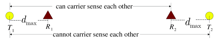
Take a two-link case shown in Fig. 6 as an example. In Fig. 6, and . So the transmitters and can not carrier-sense each other, but can sense the signal transmitted from . Suppose that is set large enough to guarantee the SINR requirements on and (both the DATA frames and the ACK frames). If transmits first, then will have sensed the signal of and the default operation in most 802.11 products is that will not attempt to receive the later signal from , even if the signal from is stronger. This will cause the transmission on link to fail. It is further shown in [8] that no matter how large the carrier-sensing range is, we can always come up with an example that gives rise to transmission failures, if the “Receiver-Capture effect” is not dealt with properly. This kind of collisions can be solved with a receiver “RS (Re-Start) mode”. With RS mode, a receiver will switch to receive the stronger packet as long as the SINR threshold for the later link can be satisfied.
Appendix B Proof of Theorem 1
Proof:
With the receiver’s RS mode, in order to prevent hidden-node collisions in 802.11 networks, we only need to show that condition (6) is sufficient to guarantee the satisfaction of both the SIR requirements (1) and (2) of all the concurrent transmission links.
Let denote a subset of links that are allowed to transmit concurrently under the Safe- setting. Consider any two links and in , we have
Because both the lengths of links and satisfy
we have the following based on the triangular inequality
We take the most conservative distance in our interference analysis (i.e., we will pack the interference links in a tightest manner given the Safe- in (6)). Consider any two links and in . The following four inequalities are satisfied:
Consider any link in . We will show that the SIR requirements for both the DATA frame and the ACK frame can be satisfied. We first consider the SIR requirement of the DATA frame. The SIR at is:
For the received signal power we consider the worst case that . So we have
| (12) |
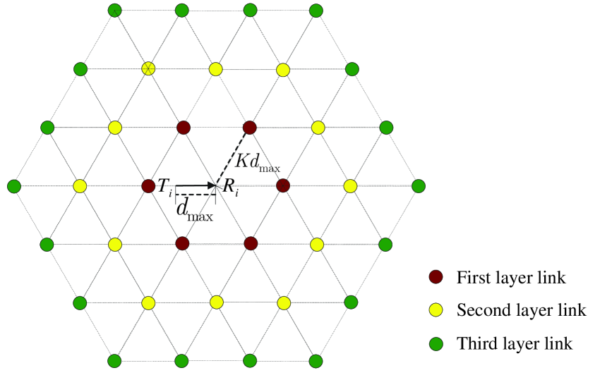
To calculate the cumulative interference power, we consider the worst case that all the other concurrent transmission links have the densest packing, in which the link lengths of all the other concurrent transmission links are equal to zero. In this case, the links degenerate to nodes. The minimum distance between any two links in is . The densest packing of nodes with the minimum distance requirement is the hexagon packing (as shown in Fig. 7).
If link is the first layer neighbor link of link , we have . Thus we have
and there are at most 6 neighbor links in the first layer.
If link is the second layer neighbor link of link , we have . Thus we have
and there are at most 12 neighbor links in the second layer.
If link is the th layer neighbor link of link with , we have . Thus we have
and there are at most neighbor links in the th layer.
So the cumulative interference power satisfies:
| (13) | ||||
| (14) |
where (13) follows from a bound on Riemann’s zeta function and (14) follows from the definition of in (7).
According to (12) and (14), we find that the SIR of the DATA frame of link at the receiver satisfies:
This means that the SIR requirement of the successful transmission of the DATA frame on link can be satisfied.
The proof that the SIR requirement of the ACK frame on link can be satisfied follows a similar procedure as above. So for any link in the concurrent transmission link set , condition (6) is sufficient to satisfy the SIR requirements of the successful transmissions of both its DATA and ACK frames. This means that, together with the receiver’s RS mode, condition (6) is sufficient for preventing hidden-node collisions in CSMA networks under the cumulative interference model. ∎
Appendix C Proof of Theorem 2
Proof:
Consider any link in the link set . Transmitter will always do carrier sensing except when it transmits DATA frame or receives ACK frame. We show that condition (10) is sufficient to prevent hidden-node collisions in the following two situations, which cover all the possible transmission scenarios:
-
1.
Link has monitored the channel for at least before its backoff counter reaches zero and it transmits.
-
2.
Link finishes a transmission; then monitors the channel for less than when its backoff counter reaches zero; then it transmits its next packet.
Let us first consider case 1:
We show that for the links that are allowed to transmit simultaneously, the separation between any pair of transmitters is no less than the safe carrier-sensing range . We use inductive proof method. Suppose that before starts to transmit, there are already links transmitting and they are collectively denoted by the link set . Without loss of generality, suppose that these links begin to transmit one by one, according to the order . For any link , let and denote the times when link starts to transmit the DATA frame and the ACK frame, respectively.
In our inductive proof, by assumption we have
| (15) |
We now show that condition (15) will still hold after link starts its transmission.
Before link starts its transmission, transmitter monitors the channel for a time period of . So at least senses increments in the carrier-sensing power that happen at time when the links in start to transmit their DATA frames. There may also be some increments in the that happen at if the links in start to transmit the ACK frames before link starting it transmission. In the IPCS mechanism, at least the following inequalities must be satisfied if can start its transmission:
Because
we have
Thus, we have shown that the separation between any pair of transmitters in the link set is no less than after link starting transmission.
Now let us consider case 2:
Before starting the transmission of the th packet, link first finishes the transmission of the th packet (from time to ), and waits for a DIFS plus a backoff time (from time to ). Let denote the set of links that are transmitting when starts the th packet at time . Consider any link in set . Because the transmission time of every packet in the network is . We know that the start time of the concurrent transmission on link must range from to , i.e., .
If , this means is in the DIFS or the backoff time of link . During this period, transmitter will do carrier sensing. The IPCS mechanism will make sure that the distance between and satisfies .
If , this means falls into the transmission time of the th packet of link . During the transmission time, is not able to do carrier sensing because it is in the process of transmitting the DATA frame or receiving the ACK frame. However, the transmitter will do carrier sensing before it starts to transmit at time . The carrier sensing done by can make sure that the distance between and satisfies .
So for any link in , we have .
∎
References
- [1] G. Brar, D. M. Blough, and P. Santi, “Computationally efficient scheduling with the physical interference model for throughput improvement in wireless mesh networks”, in Proc. ACM Mobicom, 2006.
- [2] S. A. Borbash and A. Ephremides, “Wireless link scheduling with power control and SINR constraints”, IEEE Trans. Information Theory, vol. 52, no. 11, pp. 5106-5111, Nov. 2006.
- [3] G. Sharma, R.R. Mazumdar, and N.B. Shroff, “On the Complexity of Scheduling in Wireless Networks”, in Proc. ACM Mobicom, 2006.
- [4] O. Goussevskaia, Y.A. Oswald, and R. Wattenhofer, “Complexity in Geometric SINR”, in Proc. ACM MobiHoc, 2007.
- [5] T. Moscibroda, R. Wattenhofer, and A. Zollinger, “ Topology Control Meets SINR: The Scheduling Complexity of Arbitrary Topologies”, in Proc. ACM MobiHoc, 2006.
- [6] K. Jain, J. Padhye, V. Padmanabhan, and L. Qiu, “Impact of interference on multi-hop wireless network performance,” in Proc. ACM Mobicom, 2003.
- [7] P. Gupta and P.R. Kumar, “The Capacity of Wireless Networks,” IEEE Trans. Info. Theory, Vol.46, No. 2, pp. 388-404, 2000.
- [8] L. B. Jiang and S. C. Liew, “Hidden-node Removal and Its Application in Cellular WiFi Networks”, IEEE Trans. Veh. Technol., vol. 56, no. 5, Sep. 2007.
- [9] S. Xu and T. Saadawi, “Does the IEEE 802.11 MAC protocol work well in multihop wireless ad hoc networks?” IEEE Commun. Mag., vol. 39, no. 6, pp. 130-137, Jun. 2001.
- [10] K. Xu, M. Gerla, and S. Bae, “How effective is the IEEE 802.11 RTS/CTS handshake in ad hoc networks?” in Proc. IEEE GLOBECOM, Nov. 2002.
- [11] L. B. Jiang and S. C. Liew, “Improving throughput and fairness by reducing exposed and hidden nodes in 802.11 networks”, IEEE Trans. on Mobile Computing, vol. 7, no. 1, pp. 34-49, Jan. 2008.
- [12] A. Vasan, R. Ramjee, and T. Woo, “ECHOS–Enhanced capacity 802.11 hotspots”, in Proc. IEEE Infocom, Mar. 2005.
- [13] P. C. Ng and S. C. Liew, “Throughput analysis of IEEE 802.11 multihop ad hoc networks”, IEEE/ACM Transactions on Networking, vol. 15, no. 2, pp. 309-322, Apr. 2007.
- [14] C. K. Chau, M. Chen, and S. C. Liew, “Capacity of Large-scale CSMA Wireless Networks”, to appear in ACM Mobicom, 2009.
- [15] T. S. Kim, H. Lim, and J. C. Hou, “Improving Spatial Reuse through Tuning Transmit Power, Carrier Sense Threshold, and Data Rate in Multihop Wireless Networks”, in Proc. ACM Mobicom, 2006.
- [16] T. Y. Lin and J. C. Hou, “Interplay of Spatial Reuse and SINR-determined Data Rates in CSMA/CA-based, Multi-hop, Multi-rate Wireless Networks”, in Proc. IEEE Infocom, 2007.
- [17] L. Fu, S. C. Liew, and J. Huang, “Safe Carrier Sensing Range in CSMA network under Physical Interference Model”, Technical Report, 2009. http://arxiv.org/abs/0901.3611.
- [18] K. Jamieson, B. Hull, A. Miu, and H. Balakrishnan, “Understanding the Real-World Performance of Carrier Sense”, ACM SIGCOMM Workshops, 2005.