Emergence and Complexity in Theoretical Models of Self-Organized Criticality
Statutory Declarations
| Name of the Candidate | : Tridib Sadhu |
| Title of the Thesis | : Emergence and Complexity in |
| Theoretical Models of Self- | |
| Organized Criticality. | |
| Degree | : Doctor of Philosophy (Ph.D.) |
| Subject | : Physics |
| Name of the advisor | : Prof. Deepak Dhar |
| Registration number | : PHYS–154 |
| Place of Research | : Tata Institute of Fundamental |
| Research, Mumbai 400005 |
Declaration Of Authorship
This thesis is a presentation of my original research work. Wherever contributions of others are involved, every effort is made to indicate this clearly, with due reference to the literature, and acknowledgement of collaborative research and discussions.
The work was done under the guidance of Professor Deepak Dhar, at the
Tata Institute of Fundamental Research, Mumbai.
Signed: . Date:.
Name: Tridib Sadhu
In my capacity as supervisor of the candidate’s thesis, I certify that
the above statements are true to the best of my knowledge.
Signed: . Date:.
Name: Prof. Deepak Dhar
Acknowledgements
I would like to express my gratitude to all those who helped me in the completion of this work. Most importantly, I gratefully acknowledge the guidance and support of my thesis advisor Prof. Deepak Dhar. His emphasis on perfection and strong sense of work ethics have had a deep influence on me.
I also acknowledge the financial support I received from TIFR, Mumbai.
My special thanks to Shaista for proofreading, and for helping me in many technical aspects of preparing the thesis. Finally, I would like to thank my family for their unconditional love and support.
Chapter 1 Synopsis
1.1 Introduction
The concept of self-organized criticality (SOC) was introduced by Bak Tang and Wiesenfeld in 1987 [btw], to explain the abundant fractal structures in nature, e.g. mountain ranges, river networks, power law tails in the distribution of earthquake intensities etc. The SOC refers to the non-equilibrium steady state of slowly driven systems, which show irregular burst like relaxations with a wide distribution of event sizes. The power law correlations of different physical quantities, extending over a wide range of length and time scales is a signature of criticality. Usually, reaching a critical state requires fine tuning of some control parameters e.g. temperature and magnetic field for the Ising model with a given interaction strength. However in SOC the systems reach a critical state under their own dynamics, irrespective of the initial states and without any obvious fine tuning of parameters.
In the last two decades a large amount of study is focused on understanding the mechanism of SOC. The questions regarding the universality classes of the critical states has still not been completely settled. Many theoretical models have been studied to address these issues. Most of these are cellular automata models with discrete or continuous variables, evolving under deterministic or stochastic evolution rules (see [dharphysica06] for a review). Among them the Abelian Sandpile Model (ASM) is studied the most, mainly because of its analytical tractability using the Abelian property[dharprl].
The standard ASM first proposed in [btw] is defined on a lattice with height variables at each site , which is equal to the number of sand grains at that site. There is a threshold value for each site, and any site with height is said to be unstable. The system in a stable configuration is driven by adding a single grain at a randomly chosen site. If this addition makes the system unstable, it relaxes by the following toppling rule: All the unstable sites at one time step transfers one grain each to all its nearest neighbors. Grains can move out of the lattice by toppling at the boundary. When the system reaches a stable configuration it is again driven by adding a grain and the process is repeated. The model reaches a steady state, in which the probability distribution of the size of events has power law tail.
The ASM defined on an infinite lattice when driven by adding grains only at a single site and relaxed, produces beautiful and complex patterns in height variables (see figure ). They are one of the examples where complexity arises from simple rules. In section 1.2 we analyze some of these patterns and develop a detailed and exact mathematical characterization of them.
There are different variants of the ASM that have been proposed. We study two well known models among them.
First is the Zhang model. This is similar to the ASM, but with continuous non-negative variables, usually referred as energy. At any time step all the unstable sites relax by equally distributing all its energy amongst its nearest neighbors, with their energy reducing to zero. Energy can also move out of the system by toppling at the boundary. The driving is done by adding energy to a randomly chosen site and the amount of the energy is chosen at random from a distribution.
The second is a stochastic variant of the ASM. The first stochastic sandpile model was proposed by Manna and it is known as Manna model[manna]. The model is non-Abelian, but one can construct stochastic relaxation rules with Abelian character. We consider one such stochastic Abelian sandpile model introduced in [dm]. The model is similar to the ASM with non-negative integer height variables and a threshold value defined at each site. The driving is also done by adding one sand grain at a randomly chosen site in a stable configuration. The difference is in the relaxation rules: On toppling number of grains are transfered, each grain moving independent of others to the nearest neighbors with equal probability and the height at the toppling site reduces by . For the one dimensional model defined on a linear chain, with , there are three possible events in a toppling at site : Both the neighbors and gets one grain each. Probability of this event is . Other two possibilities are that both the grains move either to the left or to the right neighbor, each event with probability .
1.2 The spatial patterns in theoretical sandpile models
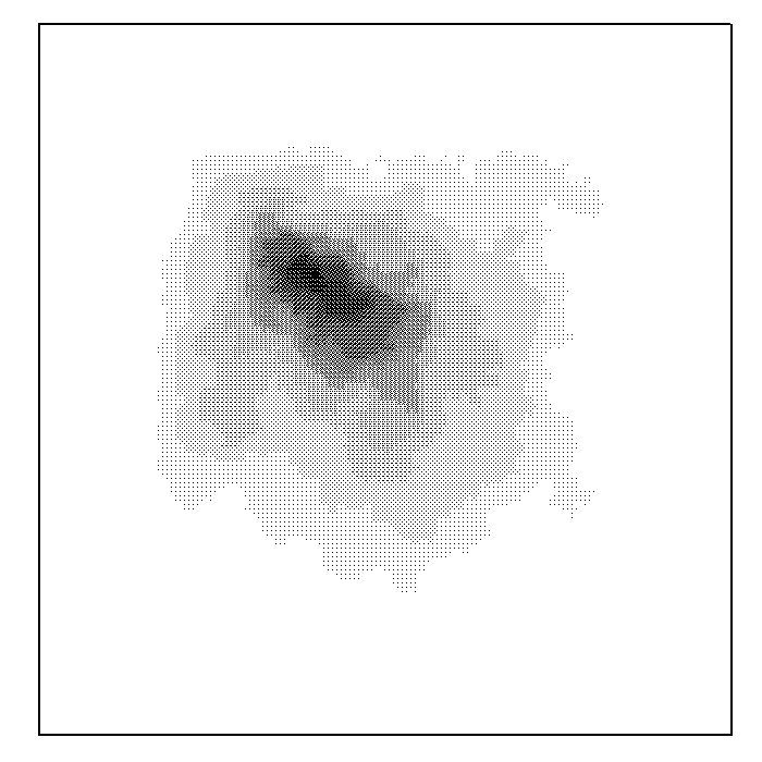
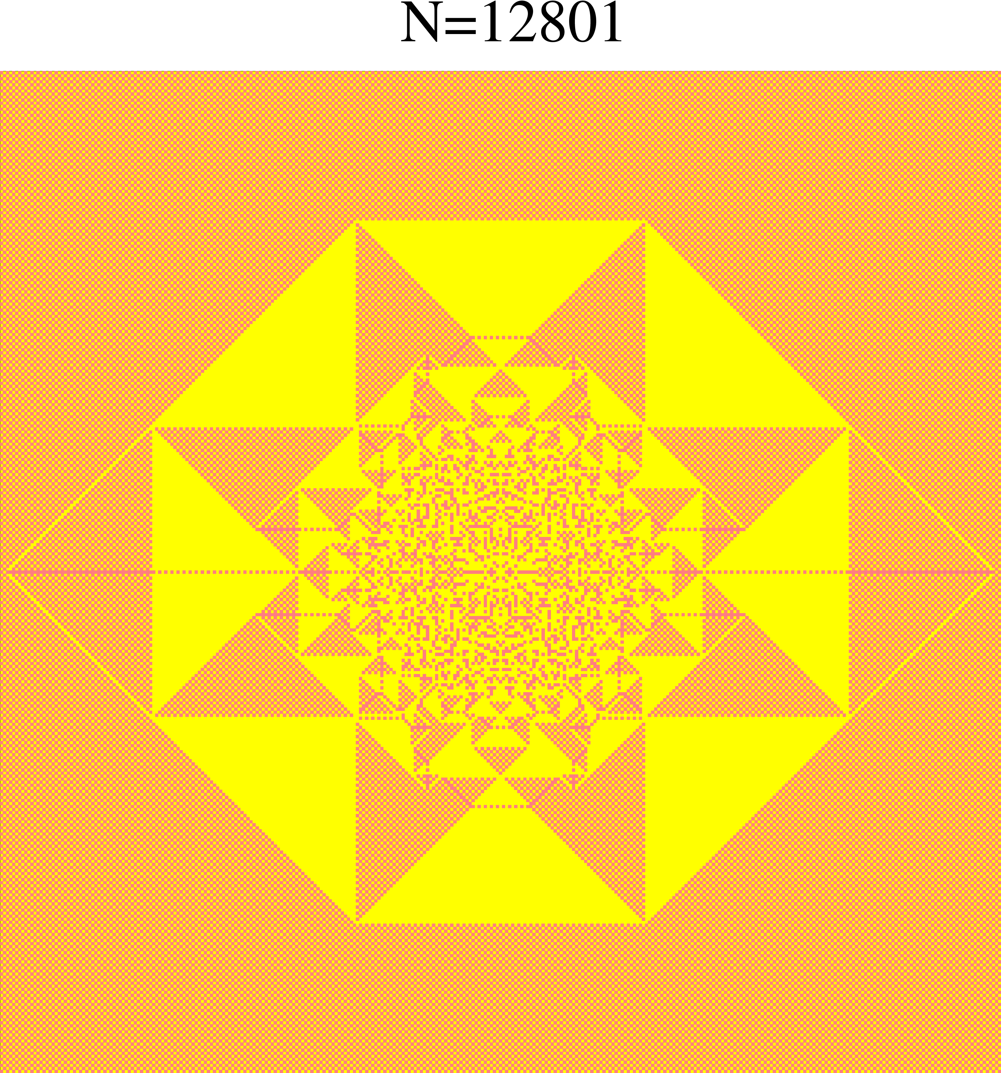
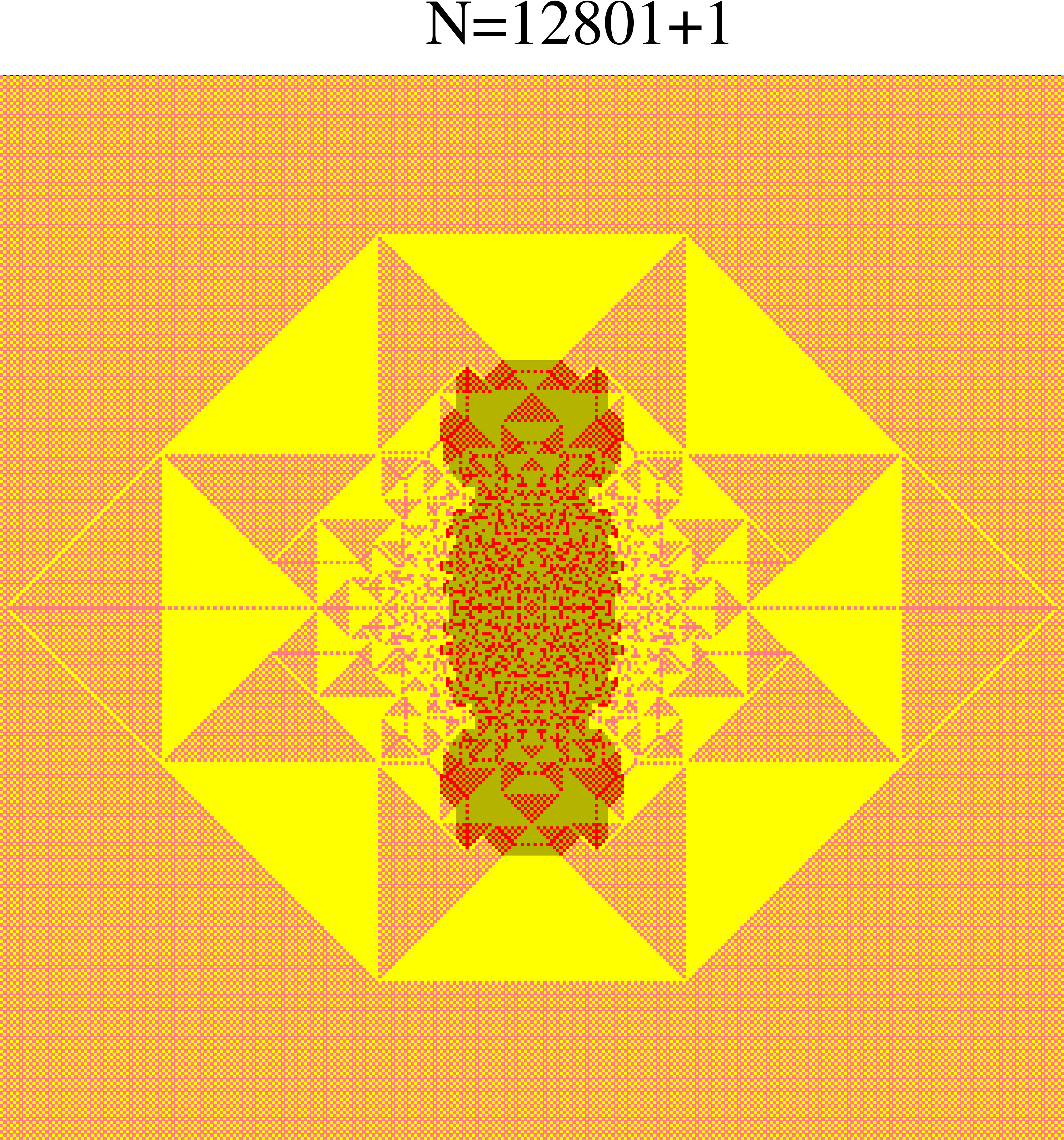
While real sand, poured at one point on a flat substrate, produces a rather simple conical pyramid shape, nontrivial patterns are generated this way in the ASM on an infinite lattice. One such pattern on a square lattice with threshold height , produced by adding grains at the origin in an initial uniform distribution of heights , is shown in the figure .


The reason for interest in these patterns is two fold.
Firstly, these are analytically tractable examples of complex patterns that are obtained from simple deterministic evolution rules. Here complexity means that we have structures with variations, and a complete description of which is long. Thus, a living organism is complex because it has many different working parts, each formed by variations in the working out of the same, but relatively much simpler genetic coding.
Secondly, these patterns have the very interesting property of proportionate growth. This is a well-known feature of biological growth in animals, where different parts of the growing animal grow at roughly the same rate, keeping their shape almost the same. Our interest in studying the sandpile patterns comes from these being the simplest model of proportionate growth with non-trivial patterns. Compare the two patterns in figure produced on the same background but with different values of . The pattern grows in size and finer features become discernible at the center, but the overall shape of the pattern remains same. Most of the other growth models studied in physics literature, such as the Eden model, the diffusion limited aggregation, or the surface deposition, do not show this property [eden, dla, barabasi]. In these models, the growth is confined to some active outer region. The inner structures, once formed are frozen in and do not evolve further in time.
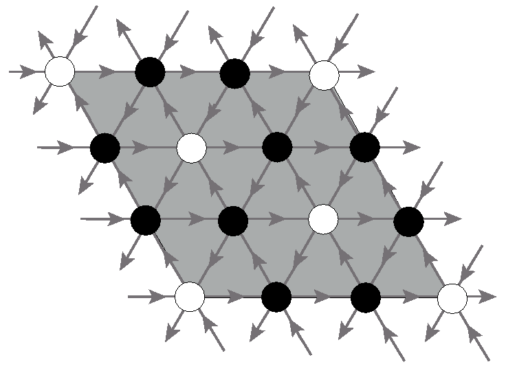
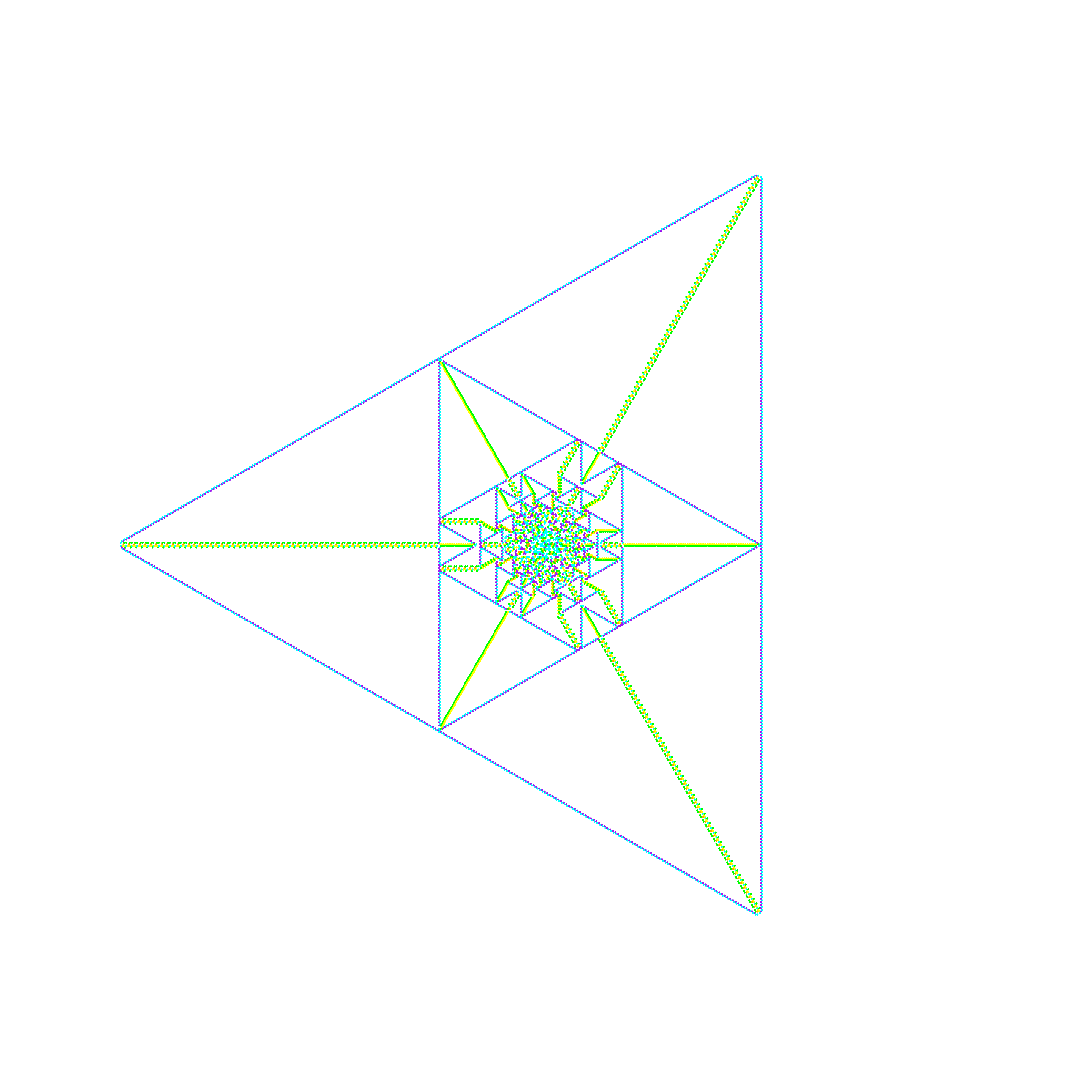
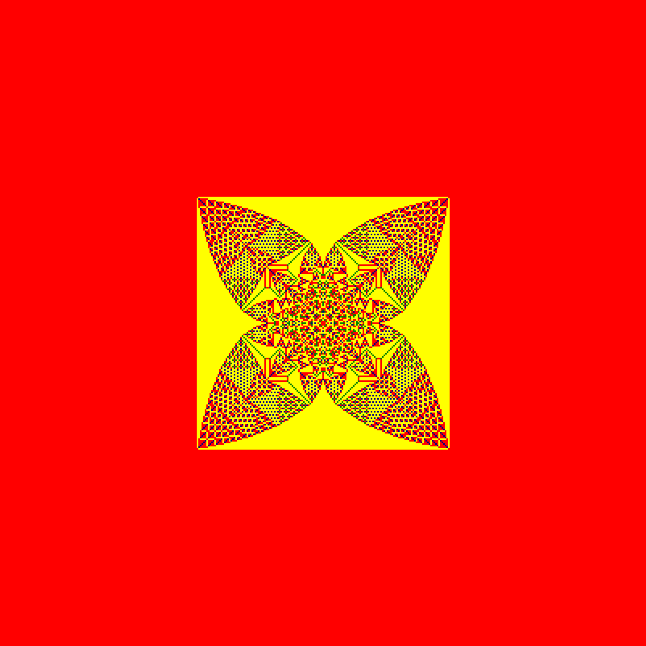
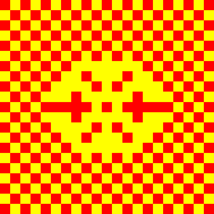
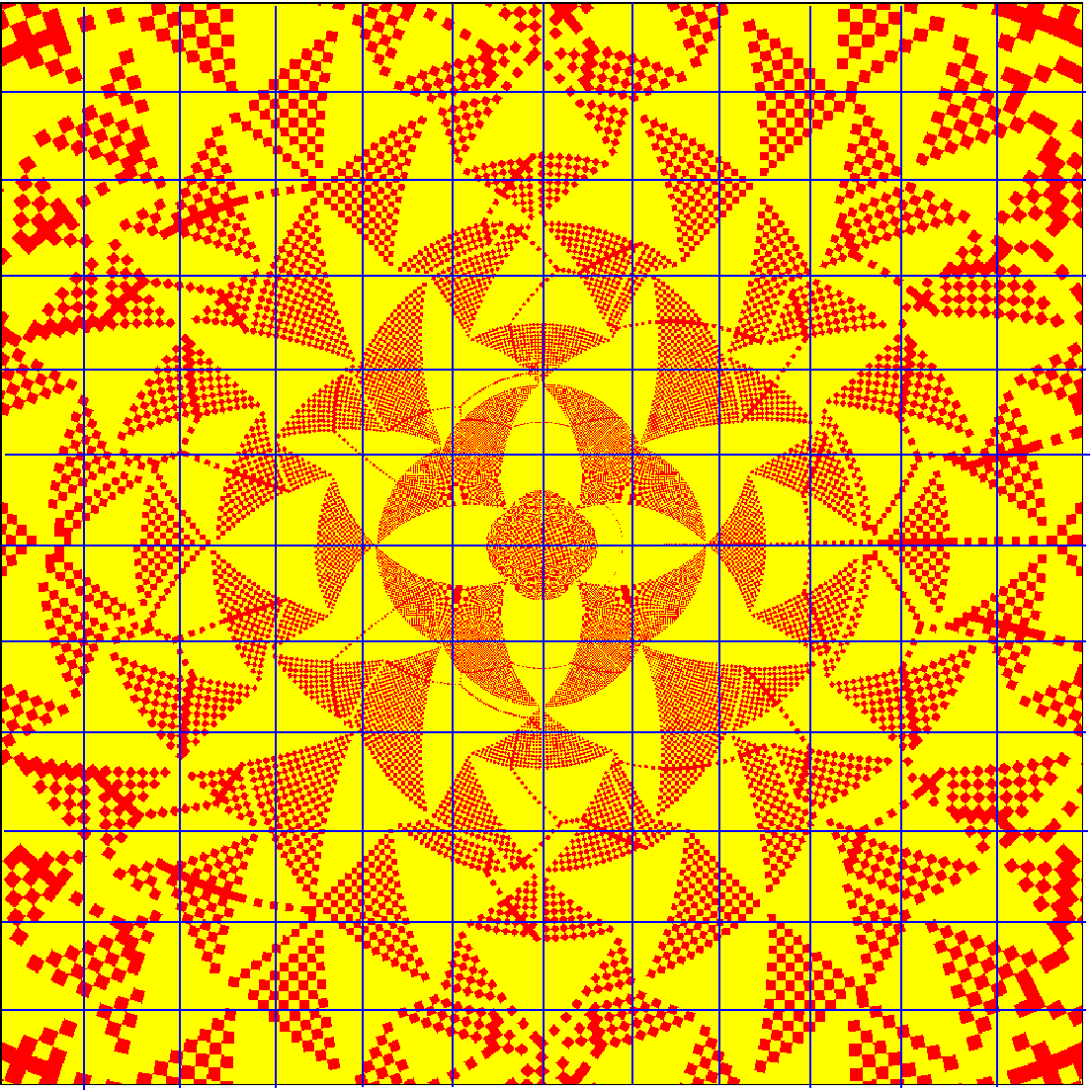
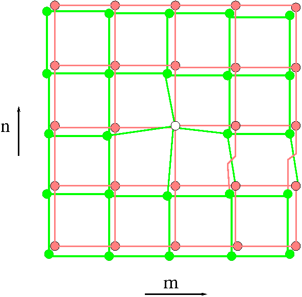
The standard square lattice produces complicated patterns and it has not been possible to characterize them so far. We consider a pattern which is simpler but still complex. The pattern is produced on the F-lattice which is a variant of the square lattice with directed edges. The lattice with checker board distribution of heights is shown in figure 1.2. Each site has equal number of incoming and outgoing arrows. The threshold height is and any unstable site relaxes by giving away one particle each in the direction of the outgoing arrows. The pattern produced by centrally seeding grains on the checkerboard background is shown in the figure 1.3.
1.2.1 The characterization of the pattern
We take some qualitative features of the observed pattern as input and show how one can get a complete and quantitative characterization of the pattern in the asymptotic limit of .
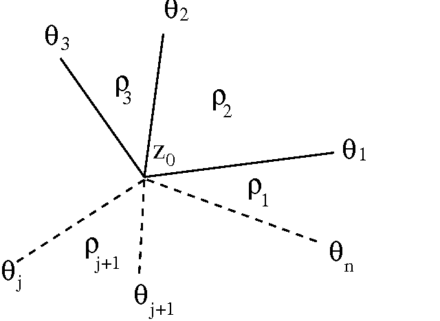
In models with proportionate growth, it is natural to describe the asymptotic pattern in terms of the rescaled coordinate where is the diameter of the pattern, suitably defined, and is the position vector of a site on the lattice. The function increases in steps with and goes to infinity as . In the asymptotic limit the pattern can be characterized by a function which gives the local density of sand grains in a small rectangle of size about the point , with where and are the x and y components of the rescaled position vector . We define as the change in density from its background value.
The pattern is composed of large regions where the heights are periodic and we call these regions as patches. Inside each patch is constant and takes only two values, either or .
Let be the number of topplings at site when number of grains have been added and then relaxed. Define a rescaled toppling function
| (1.1) |
where the floor function is the largest integer less than or equal to . From the conservation of sand grains in the toppling process, it follows that satisfies the Poisson equation
| (1.2) |
The complete specification of determines the density function and hence the asymptotic pattern. The condition that determines is the requirement that inside each patch of constant density, it is a quadratic function of and . Considering that there are only two types of patches and that satisfies (1.2) we write
| (1.3) |
for the patches with and
| (1.4) |
for the patches with . Each patch is characterized by the values of the parameters ,,, and . The continuity of and its derivatives along the boundary between two adjacent patches imposes linear relations among the corresponding parameters. Using these relations we show that and take only integer values. Each patch with its parameters , and can be labeled by the pair . The pair can be taken as the Cartesian coordinates of the adjacency graph of the patches, which for this pattern is a square lattice on a two sheeted Riemann surface. We show that the function , with , satisfies the discrete Laplace’s equation on the adjacency graph. Using the asymptotic dependence of close to the site of addition, we show that for large ,
| (1.5) |
Solution of the discrete Laplace’s equation on this adjacency graph with the above boundary condition is difficult to determine. We numerically calculate the solution on finite adjacency graphs and extrapolate our results to the asymptotic limit. We also show that the pattern has an exact eight-fold rotational symmetry.
1.2.2 The effect of multiple sources or sinks

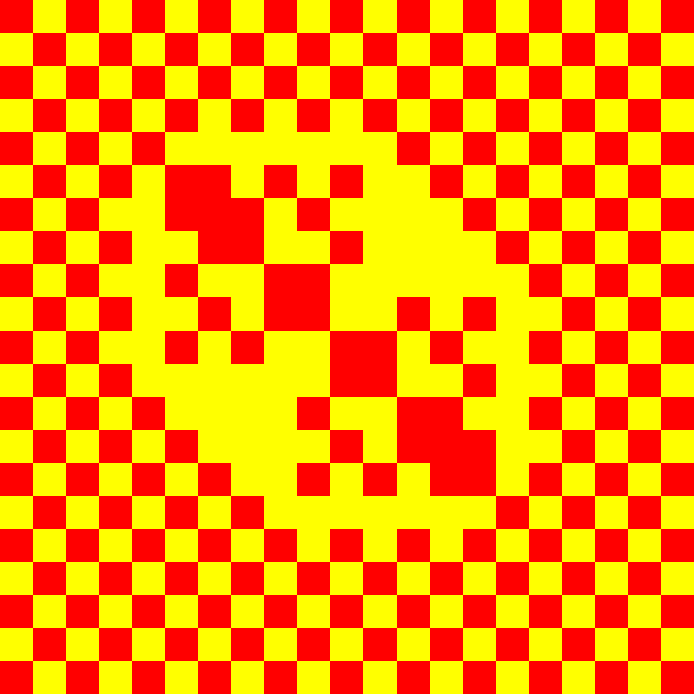
We also studied the patterns where the grains are added at more than one site or those formed in presence of sink sites. One such pattern on the F-lattice with the checker board background in presence of a line of sink sites is shown in the figure . There are still only two types of patches and like the single source case, the spatial distances can be expressed in terms of the solution of the discrete Laplace’s equation on the adjacency graph. However, the structure of the adjacency graph changes. For the pattern in figure , the adjacency graph is still a square lattice but on a Riemann surface of three sheets. We have explicitly worked out the spatial distances by numerically solving the Laplace’s equation on this graph. We have also studied the case with two sites of addition and quantitatively characterized the pattern.
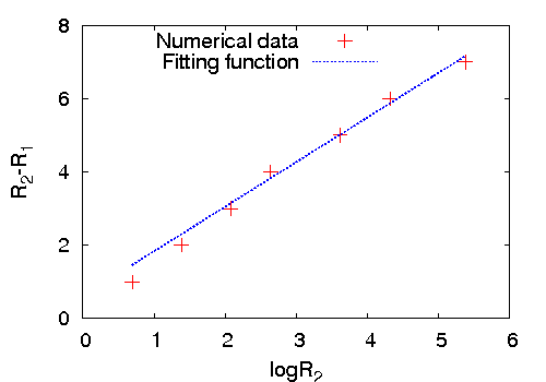
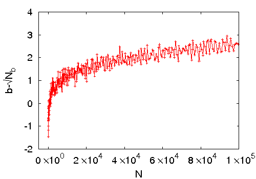
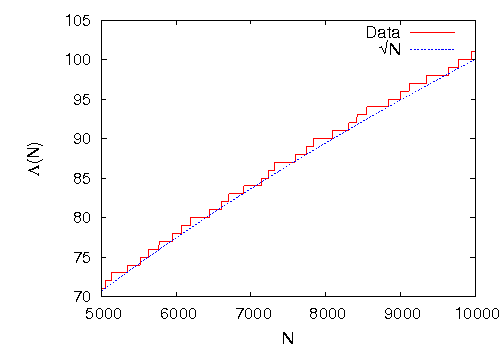
The most interesting effect of the sink sites is that it changes how different spatial lengths in the pattern scale with the number of added grains . For example, in the absence of sink sites, the diameter of the pattern in figure 1.3 grows as , for large , whereas in presence of a line of sink sites next to the site of addition, it changes to . More precisely, we show that in this case
| (1.6) |
where and are numerical constants. For and this relation describes the dependence of for in the range of to , with unexpectedly high accuracy where both sides of the above equation differs by at most .
We have also studied the case in which the source site is at the corner of a wedge angle , where the wedge boundaries are absorbing. We show that the relation similar to (1.6) is
| (1.7) |
where . This analysis is extended to other lattices with different initial height distribution, and also to higher dimensions.
1.2.3 The compact and non-compact growth
The growth rate of the patterns closely depends on the background height distribution. When the heights at all sites on the background are low enough, one gets patterns with growing as in d-dimensions. We refer to this growth as the compact growth. However if sites with maximum stable height in the background form an infinite cluster we get avalanches that do not stop, and the pattern is not-well defined. We describe our unexpected finding of an interesting class of backgrounds, that show an intermediate behavior. For any , the avalanches are finite, but the diameter of the pattern increases as , for large , with . We call this as non-compact growth. The exact value of depends on the background. These patterns still show proportionate growth.
We characterize one such pattern in the asymptotic limit for which . This pattern is produced on a triangular lattice with directed edges with the background shown in the figure 1.5. The threshold height is and the toppling rules are similar to the model on the F-lattice. The corresponding pattern is shown in figure 1.6. We show that for this pattern the rescaled toppling function is piece-wise linear in and . The adjacency graph is also simpler, it is a hexagonal lattice and like the previous examples, the spatial distances in the pattern are expressed in terms of the solution of the Laplace’s equation on this graph. We determine the solution in a closed integral form.
1.3 Emergence of quasi-units in the Zhang model
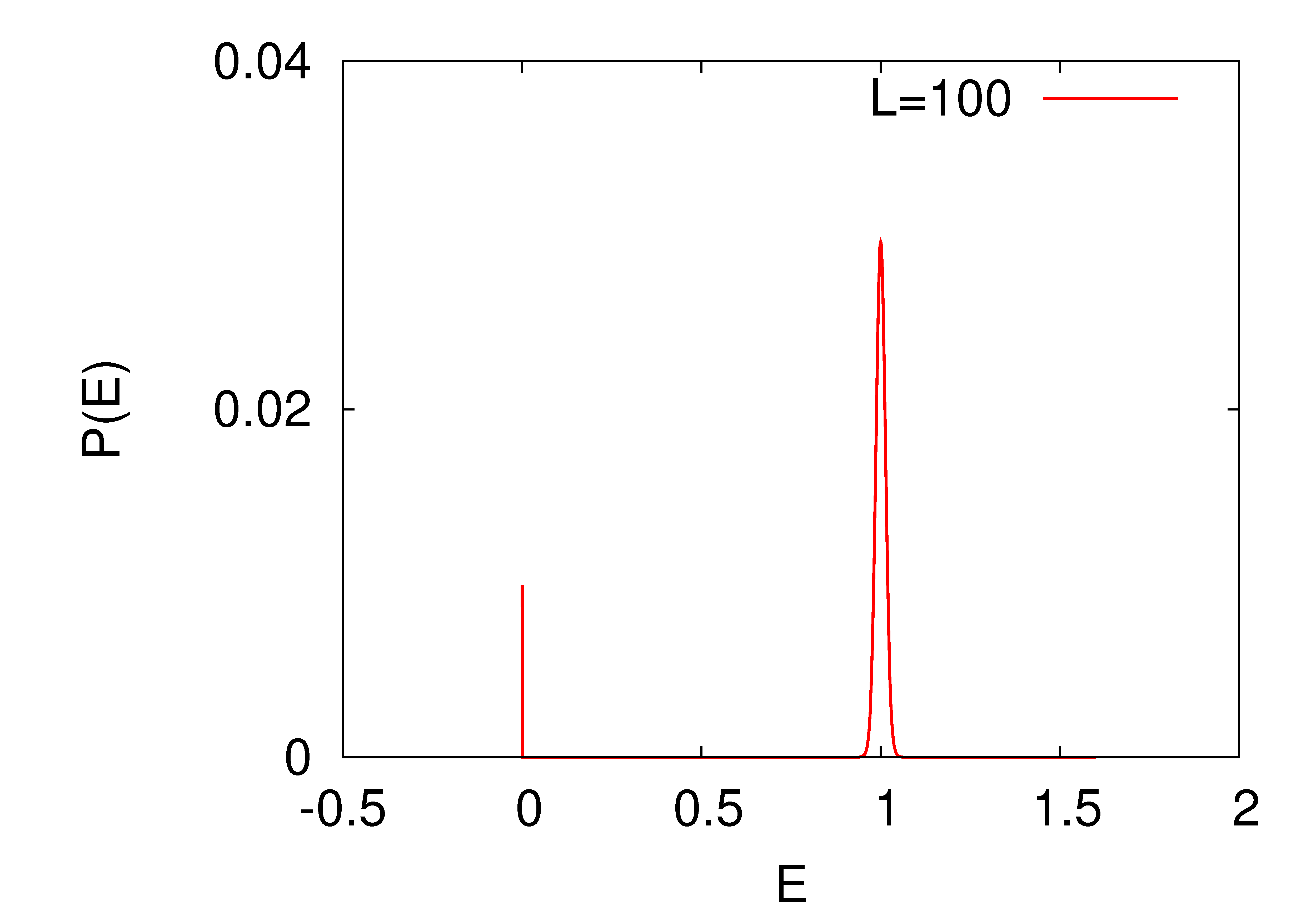
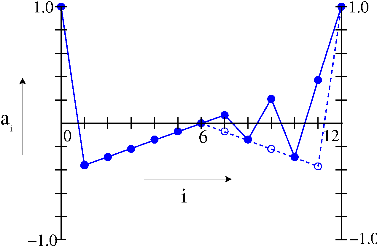
The Zhang model in one dimension has the remarkable property that in spite of the randomness in the amount of energy added during driving, the steady state energy per site has a very sharply peaked distribution in which the width of the peak is much less than the spread in the input amount. One such distribution is shown in figure 1.7. The threshold energy and the driving energy is chosen from a uniform distribution in the range . The distribution has a spike at and a peak at with a standard deviation . In general the width of the peak decreases with the increase of the system size.
This behavior was noticed in numerical simulations in both one and two dimensions, and it is called as “emergence of quasi-units”. It is argued that for large systems, the behavior would be the same as in the discrete model [zhang]. Fey et. al. [fey] have shown that for some choices of the distribution of input energy, in one dimension, the variance of energy does go to zero as length of the chain goes to infinity. However they did not show how fast the variance decreases with .
We study the emergent behavior in the one-dimensional model by looking at how the added energy is redistributed among different sites in the relaxation process. Let the amount of energy for driving at time be chosen randomly from a uniform interval . The time is counted in terms of the relaxation steps and at one time step all the unstable sites relax together. We write the amount of driving energy at time as
| (1.8) |
where is uniformly distributed in the interval . We decompose the energy variable at a site in a relaxation time step as
| (1.9) |
where refers to the nearest integer value. The integer part evolves as the integer heights in the ASM. The function is independent of and is a linear function of . The precise function depends on the evolution history which is determined by the initial configuration and the sequence of addition sites up to time . We assume that at starting time , the variable are zero for all , and the initial configuration is a recurrent configuration of the ASM. We define by
| (1.10) |
We show that this is equal to the probability of a marked grain in the corresponding ASM, added at the site at time following the history , to be found at site at time
| (1.11) |
Then we show that the variance of energy in the steady state at a site can be written as
| (1.12) |
where
| (1.13) |
The overbar denotes averaging over the evolution histories .
The function has been studied in [punya], but for the calculation is much more difficult. However analyzing the behavior in different limits we introduce a phenomenological expression for it and show that in the large limit the variance of energy at a site has a scaling form . We determine an approximate form of the scaling function
| (1.14) |
where and are numerical constants. This expression agrees very well with the results of our numerical simulation.
1.4 Stochastic models of SOC
The sandpile models with stochastic toppling rules are important subclass of SOC models. These models are able to describe the avalanche behavior seen experimentally in the piles of granular media much better than the deterministic models [osloexpt]. Also in the numerical studies, one gets better scaling collapse, and consequently, more reliable estimates for the values of the critical exponents, than for the models with deterministic toppling rules [stochnum]. There is good numerical evidence that these models constitute a universality class different from their deterministic counter parts [univ1, univ2, numbtw, numsand1, numsand2].
Unfortunately, at present, the theoretical understanding of the models with stochastic toppling rules is much less than the deterministic models, even the characterization of the steady state is not known for the one-dimensional Manna model.
We consider the Manna model with Abelian toppling rule on a linear chain of length , described in section 1.1. Any stable state of the model is expressed as a linear combination of the stable height configurations with the coefficients being the probability of finding the system in that configuration. We define an addition operator corresponding to the addition of grains at the site , which acting on a stable state takes it to another stable state achieved following the stochastic relaxation rule.
The Abelian property of the operators is shown in [dm]. However, unlike the deterministic ASM, the inverse operator need not exist. This makes the determination of the matrix form of the operators difficult for this model. In a straightforward exact numerical calculation of the steady state one needs to invert a matrix of size . We use the operator algebra of the addition operators to obtain an efficient method which requires inverting a matrix only of size .
Using the conservation of sand grains during toppling we show that
| (1.15) |
In general the operators need not be diagonalizable. However, using the Abelian property we construct a common set of generalized eigenvectors for all the operators such that in this basis the matrices simultaneously reduce to the Jordan block form. Corresponding to each block there is at least one common eigenvector. Then from eq. (1.15), the eigenvalues satisfy
| (1.16) |
with the boundary condition . We reduce this set of coupled quadratic equations to a set of linear equations by taking square root
| (1.17) |
where . There are different choices for the set of different ’s and for each such choice, we get a set of eigenvalues . In general there will be degenerate sets of eigenvalues. We show that degeneracies are possible only for and the set can at most be doubly degenerate. This implies that the largest dimension of a Jordan block is . We determine the matrix elements inside each block in terms of the solution of a set of coupled linear equations.
We define a transformation matrix between this generalized eigenvector basis and the height configuration basis.
| (1.18) |
where is the basis vector corresponding to the height configuration and is the th generalized eigenvector. Any height configuration can be generated by an appropriate sequence addition operators acting on the all empty configuration. As the action of the addition operators on the generalized eigenvectors are known, this determines the elements of the transformation matrix .
Given we can get the eigenvectors of the addition operators in the configuration basis, in particular, the steady state vector, by the inverse transformation
| (1.19) |
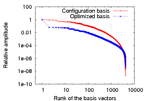
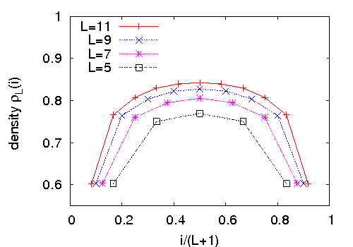
We numerically calculate the inverse matrix and determine the exact steady state for systems of small sizes. This result is then extrapolated to determine the asymptotic density profile in the steady state. Our results suggest that the steady state density averaged over all sites approaches the asymptotic density as
| (1.20) |
with which is close to the Monte Carlo estimate . We also find that the ratio of probabilities of the most probable to the least probable configuration varies as . We show that the steady state is not a product measure state.
The method described is easily generalized to other stochastic Abelian sandpile models and we discuss some examples of them.
Chapter 2 List of publications
-
(1)
Tridib Sadhu and Deepak Dhar, Emergence of quasiunits in the one-dimensional zhang model, Phys. Rev. E. (2008). no. 3, 031122.
-
(2)
Tridib Sadhu and Deepak Dhar, Steady state of stochastic sandpile models, Journal of Statistical Physics (2009), 427.
-
(3)
Deepak Dhar, Tridib Sadhu, and Samarth Chandra, Pattern formation in growing sandpiles, Europhysics Letters (2009), no. 4, 48002.
-
(4)
Tridib Sadhu and Deepak Dhar, Pattern formation in growing sandpiles with multiple sources and sinks, Journal of Statistical Physics (2010), 815.
-
(5)
Tridib Sadhu and Deepak Dhar, Pattern formation in fast growing sandpiles, Phys. Rev. E. (2012), 021107.
Chapter 3 Introduction
3.1 Self-organized criticality (SOC)
One of the most striking aspects of physics is the simplicity of its laws. Maxwell’s equations, Schrodinger’s equation, and Hamiltonian mechanics are simple and expressible in few lines. However every place we look, outside the textbook examples, we see a world of amazing complexity: huge mountain ranges, scale free coastlines, the delicate ridges on the surface of sand dunes, the interdependencies of financial markets, the diverse ecologies formed by living organisms are few examples. Each situation is highly organized and distinctive, but extremely complex. So why, if the basic laws are simple, is the world so complicated? The idea of Self Organized Criticality was born aiming to give an explanation for this ubiquitous complexity [jensen]. In this chapter the basic concepts related to SOC, that will be important for this thesis, are introduced.
The examples, cited above, share a common feature: a power-law tail of the correlations. Consider the two point correlation of a quantity , where is the height at a place in a mountain range, and is its average value. The function increases as , with the exponent varying very little for different mountain ranges. Similar distribution with extended tails is observed in many other natural phenomena: Gutenberg-Richter law in earth quake [gutenberg], Levy distribution in stock market price variations [levy], Hacks law in River networks [hackslaw1, hackslaw2] etc. Such power-law distributions entail scale invariance — there are no macroscopic spatial scales other than the system size, in terms of which one can describe the system, making it complex.
Such features are familiar to physicist in equilibrium systems undergoing phase transition. In standard critical phenomena there are control parameters such as temperatures, magnetic field, which requires to be fine tuned by an external agent, to reach the critical point. This is unlikely to happen in naturally occurring processes such as formation of mountain ranges, earth quakes or even stock markets. These are non-equilibrium systems brought to their present states, by their intrinsic dynamics — and not by a delicate selection of temperature, pressure or similar control parameters. 111Per Bak, in his book [blind], puts this in an interesting comment—“The nature is operated by a ’blind watchmaker’ who is unable to make continuous fine adjustments”.
In the summer of 1987, Bak, Tang and Wiesenfeld(BTW) published a paper [btw] proposing an explanation to such ubiquitous scale invariance. They argued that the dynamic which gives rise to the robust power-law correlations seen in the non-equilibrium steady states in nature must not involve any fine tuning of parameters. It must be such that the systems under their natural evolution are driven to a state at the boundary between the stable and unstable states. Such a state then shows long range spatio-temporal fluctuations similar to those in equilibrium critical phenomena. The complex features appear spontaneously due to a cooperative behavior between the components of the system. They called this self-organized criticality as the system self-organizes to its critical steady state.
SOC nicely compliments the idea of chaos. In the latter, dynamical systems with a few degrees of freedom, say as little as three, can display extremely complicated behavior. However, a statistical description of this randomness is predictable in the sense that, the signals have a white noise spectrum, and not a power law tail. A Chaotic system has little memory of the past, and it is easy to give a statistical description of such behavior. In short, chaos does not explain complexity. On the other hand, in SOC, generally, we start with systems of many degrees of freedom, and find a few general features which are also statistically predictable, but has a power-law spectra leading to complex behavior. In certain dynamical systems, e.g., logistic maps, there are points (the Feigenbaum point [chaos]) in the parameter space, which separates states with a predictable periodic behavior and chaos. At this transition point there is complex behavior, with power-law correlations. SOC gives description of how systems, under their own dynamics, without external monitoring, reaches this very special point (“edge of chaos”), explaining the robust complex behavior in natural systems.
In the book “How nature works?”, Per Bak gives various kinds of natural examples of SOC, of which the canonical one is the sandpile. On slowly adding grains of sand to an empty table, a pile will grow until its slope becomes critical and avalanches start spilling over the sides. If the slope is too small, each grain just stays at the place where it lands or creates a small avalanche. One can understand the motion of each grain in terms the local properties, like place, the neighborhood around it etc. As the process continues, the slope of the pile become steeper and steeper. If the slope becomes too large, a large catastrophic avalanche is likely, and the slope will reduce. Eventually, the slope reaches a critical value where there are avalanches of all sizes. At this point, the system is far out of balance, and its behavior can no longer be understood in terms of the behavior of localized events. The system is invariably driven towards its critical state.
3.2 Theoretical models
In order to have a mathematical formulation of SOC, BTW studied a so-called cellular automata known as the sandpile model [btw], which is discrete in space, time and in its dynamical variables. The model is defined on a two dimensional square lattice where each site has a state variable referred as height, which takes only positive integer values. This integer can be thought of as representing the amount of sand at that location or in another sense it represents the slope of the sandpile at that point. Neither of these analogies is fully accurate, the model has aspects of both. One should consider it as a mathematical model of SOC, rather than an accurate model of physical sand.
A set of local dynamical rules defines the evolution of the model: At each time step a site is picked randomly, and its height is increased by unity. In this thesis, this step will be referred as the driving. If the height now is greater than or equal to a threshold value , the site is said to be unstable. It relaxes by toppling whereby four sand grains leave the site, and each of the four neighboring sites gets one grain. If there are any unstable sites remaining, they too are toppled, all in parallel. In case of toppling at a site at the boundary of the lattice, grains falling outside the lattice are removed from the system. This process continues until all sites are stable. This completes one time step. Then, another site is picked randomly, its height is increased by , and so on.
The following example illustrates the dynamics. Let the lattice size be and suppose at some time step the following configuration is reached where all sites are stable.
|
We now add a grain of sand at randomly selected site: let us say the central site is chosen. Then the configuration becomes the following
|
The central site is not stable, and therefore it will topple and the configuration becomes
This configuration has two unstable sites, so both will topple in parallel. Since these are at the boundary, two grains will be lost, on toppling. The new result is
and further toppling leads to
|
This is a configuration with all sites stable. One speaks in this case of an avalanche of size , since there are four topplings. Another measure is the number of steps required for relaxation, which in this case is . For large lattices, in the steady state, the distribution of avalanche sizes and durations display a long power-law tail, with an eventual cutoff determined by the finite size of the system.
Since the original sandpile model by BTW a large number of variations of the model have been studied (see [dharphysica06, jensen] for reviews). These are mostly extended systems with many components, which under steady drive reaches a steady state where there are irregular burst like relaxations and long ranged spatio temporal correlations. It is to be noted that in these models the complexity is not contained in the evolution rules itself, but rather emerges as a result of the repeated local interactions among different variables in the extended system.
In the rest of this chapter, I will introduce three of the most studied models of sandpile and the techniques used to analyze them.
3.2.1 Deterministic abelian Sandpile Model (DASM)
This is the most studied model due to it analytical tractability. In a series of papers, Deepak Dhar and his collaborators have shown that this model has some remarkable mathematical properties. In particular, the critical state of the system has been well characterized in terms of an abelian group. In the following I will generally follow the discussion in [dharphysica06].
The model is a generalized BTW model on any general graph with sites labeled by integers . To make things precise, I will start with some definitions. A configuration for the sandpile model is specified by a set of integer heights defined on the sites of the graph. We denote a threshold value of the height at a site as . The system is driven like the BTW model by adding one sand grain at a randomly chosen site which increases the height at that site by . The toppling rules are specifies by a toppling matrix such that on toppling at site , heights at all sites are updated according to the rule:
| (3.1) |
For example in the BTW model on a square lattice
| (3.2) |
Evidently the matrix has to satisfy some conditions to ensure that the model is well behaved. These are
-
1.
, for all . (Height decreases at the toppled site)
-
2.
, for all . (Heights at other sites are increased or unchanged)
-
3.
for all . (Sand is not generated in toppling)
-
4.
Each site is connected through toppling events to at least one site where sand can be lost, such as the boundary.
Without loss of generality we choose (This only amounts to defining the reference level for the height variables).
With this convention, if all are initially non-negative they will remain so, and we restrict ourself to configurations belonging to that space, denoted by . Let be the space of stable configurations denoted by where the height variables at each site are below threshold. The property above ensures that stability will always be achieved in a finite time.
We formalize the addition of sand to a stable configuration by defining an “addition operator” so that is the new stable configuration obtained by taking and then relaxing.
The mathematical treatment of ASM relies on one simple property it possesses: The order in which the operations of particle addition and site toppling are performed does not matter. Thus the operators commute i.e.
| (3.3) |
The proof uses the linearity of the toppling processes [dharphysica06]. In the relaxation processes represented by the two sides of the above equation, the order of topplings can be changed, but the final configurations are equal. An example of this abelian nature is the process of long addition of multi-digit numbers. In this example the toppling process is like carrying.
Note that, there are some “garden of Eden” configurations that once exited can not be reached again. For example, in the BTW model on square lattice, system can never reach a state with two adjacent . This is because in trying to topple a site to zero, the neighbor gains a grain, and vice versa. This leads to the definition of the recurrent state space which consists of any stable configuration that can be achieved by adding sand to some other recurrent configuration. This set is not empty since one can always reach a minimally stable configuration defined by having all .
Dhar proved [dharprl] another remarkable property that the addition operators have unique inverses when restricted to the recurrent space; that is, there exists a unique operator such that for all in . This can be easily seen from the fact that there are finite number of configurations in , so for some positive period , with a recurrent configuration. Using the abelian property it can be shown that the period is same for all . Then is the inverse for .
These properties of have some interesting consequences [dharprl]. One is that in the steady state all the recurrent configurations are equally probable. Also, the number of recurrent states is simply the determinant of the toppling matrix . For large square lattices of sites this determinant can be found easily by Fourier transform. In particular, whereas there are stable states, there are only recurrent states. Thus starting from an arbitrary state and slowly adding sand, the system self-organizes to an exponentially small subset of states, which are the attractor of this dynamics.
There are many more interesting properties of the DASM, e.g., using a burning algorithm [burning], it is possible to test whether an arbitrary configuration is recurrent. Using this algorithm it can also be shown that the model is related to statistics of spanning-trees on the lattice, as well as with the limit of the Potts model [burning, dharphysica06]. As several results are known about spanning tree these equivalence help in relating properties of DASM to known properties of spanning trees.
In spite of these interesting mathematical properties, the exponents characterizing the power-law tail in the distribution of avalanches are still difficult to determine analytically on most lattices, and computer simulations are still needed. In fact, on a square lattice, the numerical values estimated by different people have shown a wide range of values. It has been argued that the simple finite size scaling does not work for the avalanche distribution and instead it has a multi-fractal character [kadanoff]. In some simpler quasi-one dimensional lattices it has been shown that simple linear combination of two scaling forms provides an adequate description [ali].
For higher dimensional lattices it has been shown by Priezzhev that the upper critical dimension for the models is [ucd]. For lattices of dimension above , the avalanche exponents take mean field values and can be deduced from the exact solution of the model on a Bethe lattice [bethe].
3.2.2 Zhang model
The Zhang model, introduced by Zhang in 1989, differs from the DASM in two aspects: first, the height variables are continuous and takes non-negative real values. A site is unstable if its height is above threshold, and it topples by equally dividing its entire content among its nearest neighbors, and itself becoming empty. Second, the external perturbation is not by adding height , but by a quantum chosen randomly from an interval , where are positive real numbers.
Here, is an example of the Zhang model in one dimension. Let the threshold height is , same for all , and an initial configuration is
|
Now a time step begins by an addition to a random site, of a random amount chosen from the interval . Let the amount is and the site is the central site. After addition the result is
|
Because the middle site is unstable, an avalanche starts:
In case of two or more unstable sites, all are toppled in parallel.
Since the addition amount is random, a stable site could in principle have any height between zero and the threshold and the stationary distribution could be very different from that of the DASM, where only discrete values are encountered. Nevertheless, when one simulates the model on large lattices in one and two dimensions, the stationary heights tend to concentrate around nonrandom discrete values. This is known as the “emergence of quasi-units” [zhang]. It appears that altering the local toppling rules of the DASM, does not have that much effect on the global behavior after all, if the lattice size is large.
This behavior led to the conjecture that in the thermodynamic limit the critical behavior is identical to that of DASM. However, due to the changed toppling rules, the dynamics is no longer abelian, and determining the steady state is quite difficult, even in one-dimension. In fact, Blanchard et. al. have shown that the probability distribution of heights in the steady state, even for the two site problem, has a multi-fractal character [blanchard].
This status was unchanged for over a decade until Fey et. al. showed that on a one-dimensional lattice, for some specific choice of the amount of addition, the toppling becomes abelian. Using this they showed that, indeed, the model is on the same universality class of the DASM. However, the analysis in two dimension is still an open problem.
3.2.3 Manna model
Another important class of the sandpile models are with stochastic toppling rules. The first model of its kind was studied by Manna in 1991, and is known as the Manna model [manna].
The evolution rules of this sandpile in -dimensions are very similar to the ones defined for the DASM. In fact, the driving rule and the dissipation rules at the “boundary” remain the same. But in a toppling, an unstable site redistributes all the sand grains between sites randomly chosen amongst its nearest neighbors.
The randomness in the evolution rule is a relevant change in the dynamics, which makes it non-abelian. It is possible to get back the abelianness by a simple modification in the toppling rule, which I will discuss in detail in the later chapters. However, the addition operators defined appropriately do not form a group anymore and this makes the analysis less tractable even for a linear chain.
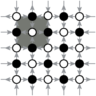
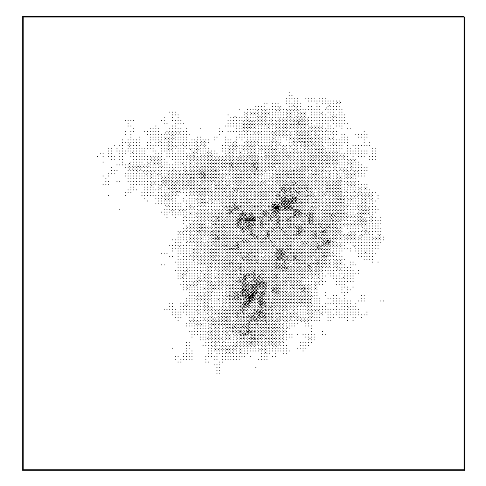
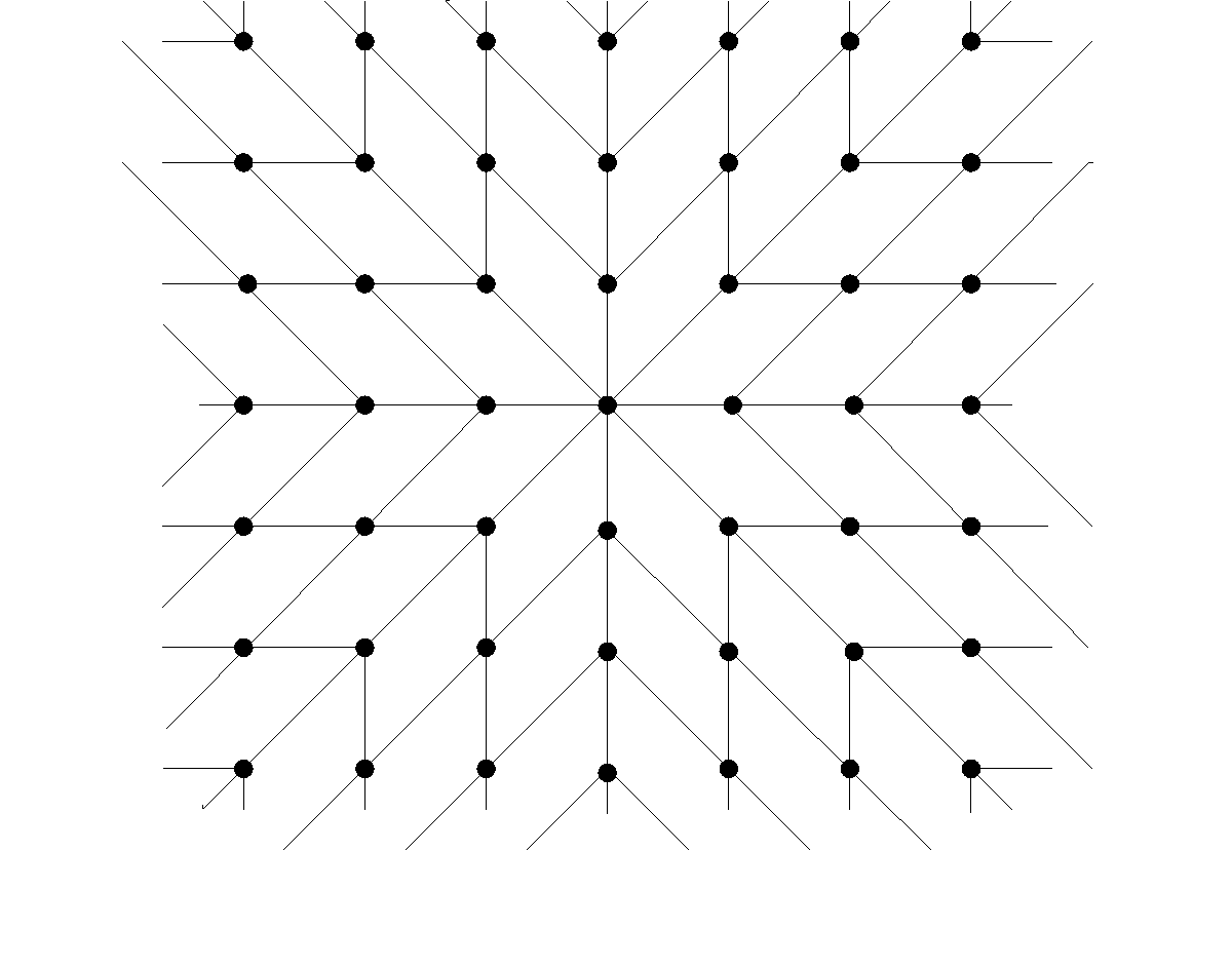
The steady state is very different from its deterministic counter part e.g. on a simple linear chain the different recurrent states are not equally probable, unlike the deterministic model. Also the avalanche distribution can be satisfactorily described by simple finite size scaling. Another evidence of the differences between these models is in the way the avalanches spread over the lattice [milshtein]. The distribution of number of toppling per site in a typical avalanche for both DASM and Manna model on a square lattice are shown in Fig. 3.1. For the DASM, one can see a shell structure in which all sites that toppled times form a connected cluster with no holes, and these sites are contained in the cluster of sites that toppled times, and so on. On the other hand, the toppling distribution exhibits a random avalanche structure with many peaks and holes.
For many years, the universality of the manna model was a controversial question. At present there are convincing numerical evidences that in dimension up to , they have a different critical behavior, from its deterministic counterpart, with a different set of critical exponents. However in dimensions , both DASM and Manna model take the same mean-field values of critical exponents.
3.3 Universality in the sandpile models.
Since the work by BTW, a large number of different models have been studied e.g. sandpile models with many variations of the BTW toppling matrix [kadanoff] or sand grain distribution rules [maslov], stochastic topplings [manna], with activity inhibition [manna2], continuous height models [zhang], loop erased random walk [loop], Takayasu aggregation model [takayasu], train model [train1, train2], non-abelian sandpile directed sandpile model [lee, pan, threshold, pruessner], forest-fire model [forest], Olami-Feder-Christensen model [ofc] etc (and many more could have been defined). Most of these models could only be studied numerically, and for a while it seemed that each new variation studied belong to a new universality class each with its own set of critical exponents. It is a fair question to ask, what is the generic behavior?
Although this question is not yet resolved completely, by now, there has been a fair amount of understanding of this problem. The universality classes with renormalization group flow in these models can be summarized in the Fig. 3.2.
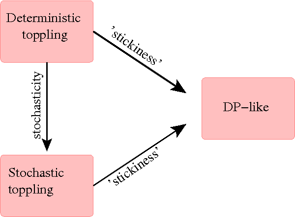
There are sufficient numerical evidence that sandpile models with deterministic toppling rules (DASM) and stochastic toppling rules (Manna model) constitute different universality classes. There are also several other model which show critical exponents different from these two [sneppen1, sneppen2, grass]. They are related to the directed percolation (DP) [dp], which describes the active-absorbing state phase transition in a wide class of reaction-diffusion systems. The activity in avalanches in sandpile can grow, diffuse or die, and any stable configuration is an absorbing state. Thus one would expect that in general the sandpile should belong to the universality class of active-absorbing state transition with many absorbing states [path]. However, these models do not involve any conserved fields. In Manna and DASM-type models, it is this presence of conservation laws of sand that makes the critical behavior different from DP [vespignani].
Recently, the effect of non-conservation has been explicitly studied [mohanty1, mohanty2] by introducing stickiness in the toppling rules (i.e. there is small probability that the incoming particles to a site get stuck there, and do not cause any toppling until the next avalanche hits the site, thus in effect there is no conservation of grains within an avalanche). It has been argued that as long as the sand grains have non-zero stickiness, the distribution of avalanche sizes follows directed percolation exponents. The DASM, and the stochastic Manna-type models are unstable to this perturbation, and the renormalization group flows are directed away from them to the directed percolation fixed point, as schematically shown in the figure. This picture is exactly verified in directed sandpiles. However, the argument is less convincing for undirected models, and the issues is not settled [bonachela2].
3.4 Experimental models of SOC
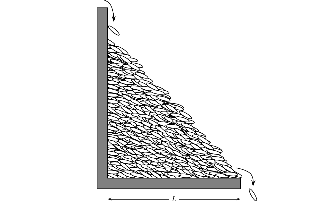
Soon after the sandpile model was introduced, several experimental groups measured the size distribution of avalanches in granular materials. Unfortunately, real sandpile do not seem to behave as the the theoretical models. Experiments show large periodic avalanches separated by quiescent states with only limited activity. While for small piles one could try to fit the avalanche distribution with power-law over a limited range, the behavior would eventually cross over, on increasing the system size, to a state which is not scale-invariant [sandexpt1, sandexpt2]. It is later realized that inertia of rolling grains is the reason for non-criticality. A large avalanche propagating over a surface with slope scours the surface, and takes away materials from it. The final angle, after the avalanche has stopped, is bellow . So if we want to see power-law avalanches, we have to minimize the effect of inertia of the grains. This is achieved in an experiment in Oslo by using rice grains. Because of the elongated shape of the rice grains (Fig. 3.3) frictional forces are stronger and these poured at very small rate gave rise to a convincing power-law avalanche distribution [osloexpt].
A similar power law distribution of avalanche sizes are obtained in motion of domain walls in ferro-magnets [feromag1, feromag2] and flux lines in type II superconductors [sup1, sup2]. A more recent experimental realization of SOC is obtained in suspensions of sedimenting non-brownian particles by slow periodic shear [corte].
It is worth mentioning that SOC has been invoked in several other situations in geophysics (atmospheric precipitation [presp], river pattern due to erosion [erotion], landslides [land]), biology (neural-network [nunet]), economics (stock-market crashes [smcr]) and many more. I have deliberately chosen the above experimental examples for which experimental observations are accurate and reproducible.
3.5 Remarks
Originally, SOC was proposed with the aim of providing an explanation of the ubiquitous complexity in nature [btw]. The abundance of fractal structures in nature, temporal as well as spatial, was considered to be an effect of a generic tendency — pertinent to most many-body systems — to develop by themselves in to a critical scale-invariant state.
However, certainly not all systems that organize themselves into one specific state will, when gently driven, exhibit scale invariance in that self-organized state. The experiments of real sandpiles referred earlier are a prime example. Neither is all observed power law behavior are an effect of dynamical self-organization into a critical state. The work by Sethna and co-workers on Barkhausen noise [sethna] is an interesting example of this, what Didier Sornette has called “Power laws by sweeping of an instability” [sornet].
Since the introduction of the idea, a large amount of discussion went into understanding the minimum conditions for a model to be self-organized critical. Though a broad picture has emerged in last two decades, it is still not complete and controversial. In the rest of this section, I will discuss two of the most discussed properties, using both examples and counter examples.
-
•
Slow driving limit. There is a strong belief in the community that an essential ingredient of SOC is slow driving (driving and dynamics operating at two infinitely separated timescales, i.e. avalanches are instantaneous relative to the time scale of driving). This idea got widely accepted after an argument given by Dickman et. al..[path] They argued that the dynamics in the sandpile model implicitly involve tuning of the density of grains to a value where a phase transition takes place between an active state, where topplings take place, and a quiescent “absorbing” state. When the system is quiescent, addition of new particles increases the density. When the system is active, particles are lost to the sinks via toppling, decreasing the density. The slow driving ensures that these two density changing mechanisms balance one another out, driving the system to the threshold of instability.
However in the Takayasu model of aggregation [takayasu] the driving is fast. A simple example, it can be defined on a linear chain on which particles are continuously injected, diffuse and coalesce. One can write the explicite rules as follows:
-
–
At each time step, each particle in the system moves by a single step, to the left or to the right, taken with equal probability, independent of the choice at other sites.
-
–
A single particle is added at every site at each time step.
-
–
If there are more than one particle at one site, they coalesce and become a single particle whose mass is the sum of the masses of the coalescing parts. In all subsequent events, the composite particles acts as a single particle.
The probability distribution of total mass at a randomly chosen site, has power law tail, with an upper cutoff that increases with time. This is a signature of criticality. The analogue of avalanches in this model is the event of coming together of large masses. In fact, it can be shown [dharphysica06] that the model is equivalent to a directed version of sandpile. In this example, it is clear that the driving is fast, and the rate is comparable to the local movements of the particles.
-
–
-
•
Conservation. Conservation of grains is also considered as a key property for the criticality to emerge in sandpile models. A simple intuitive argument goes as follows: the sand grains introduced in the pile can dissipate only by reaching the diffusive “boundary” of the lattice. Owing to this and because of the vanishing rate of sand addition, arbitrarily large avalanches (of all possible sizes) must exist for an arbitrarily large system size, yielding a power-law size distribution. In contrast, in the presence of non-vanishing bulk dissipation, grains disappear at some finite rate, and avalanches stop after some characteristic size determined by the dissipation rate. This clearly says that bulk dissipation is a relevant perturbation in the sandpile dynamics and breaks the criticality [bonachela1].
There are also some other models of SOC like Forest fire [forest], OFC model [ofc] where it was shown, mostly numerically, that non-conservation in the dynamics leads to non-critical steady state.
However, extrapolating these results and considering conservation as a neccesarry criteria for SOC, in general, is not correct. A model which is clearly non-conservative and still, when slowly driven displays power-law in the avalanche size distribution is discussed in [ice]. Another two non-conservative models of SOC are a sandpile model with threshold dissipation[thresdis], and Bak-Sneppen model of evolution [sneppen2].
Finally, one could ask: Has SOC, taught us anything about the world that we did not know prior to it? Jensen addresses this question very nicely in his book. The most important lesson is that, in a great variety of systems, particularly for slowly-driven-interaction- dominated-threshold systems, it is misleading to neglect fluctuations. In these systems, sometimes, the fluctuations are so large that the fate of a major part of the system can be determined by a single burst of activity. Dinosaurs may have become extinct simply as a result of an intrinsic fluctuation in a system consisting of a highly interconnected and interacting web of species; there may be no need for an explanation in terms of external bombardment by meteorites. Fluctuations are so large that the "atypical" events decides the future of the system. This new insight is sufficiently important to justify and inspire more theoretical, and experimental research in SOC.
3.6 Overview of the later chapters
The work in this thesis ranges from characterizing the spatial patterns in sandpile model, to quasi-units in the stationary distribution of Zhang’s model, and determining exact steady state of Manna model. The first three chapters in the following are about sandpile as a growth model, where we show how well-structured non-trivial patterns emerge at large length scales, due to local interactions in cellular lengths where the patterns are not obvious. In chapter 7 we discuss another emergent behavior in the Zhang model. Chapter 8 contains an operator algebraic analysis of the stochastic sandpile models. Here is a brief summary of these chapters.
-
Chapter 4: While a considerable amount of research went into characterizing the universality classes of sandpile models and understanding the mechanism of SOC, very limited work is done about spatial patterns in sandpile models. Such patterns were noted around the time when sandpile was first introduced [liu]. Yet, very little is known about them.
This chapter is devoted to the study of a class of such spatial patterns produced by adding sand at a single site on an infinite lattice with initial periodic distribution of grains and then relaxing using the DASM toppling rules. We present a complete quantitative characterization of one such patterns. We show that the spatial distances in the asymptotic (in the limit when large number of grains are added) patterns produced by adding a large number of grains, can be expressed in terms solution of discrete Laplace’s equation (discrete holomorphic functions [duffin, mercat, laszlo]) on a grid on two-sheeted Riemann surface.
We also discuss the importance of these patterns as a paradigmatic model of growth where different parts of the structure grow in proportion to each other, keeping their shape the same. We call these kind of growth as proportionate growth. We discuss the importance of such growth in real world examples.
-
Chapter 5: In this chapter we describe how the pattern changes in presence of absorbing sites, reaching which the grains get lost and no longer participate in the avalanches. We show that, again, the asymptotic pattern can be characterized in terms of discrete holomorphic functions, but on a different lattice. Similar effects of multiple sites of addition on the pattern are also calculated.
The most interesting effect of the sink sites is the change in the rate of growth of the pattern. In absence of sink sites the diameter of the pattern, suitably defined, increases as where is the number of sand grains added in the lattice. When the pattern grows with the sink sites inside, the growth rate of the diameter changes, in general, to , where the exponent depends on the sink geometries. For example, , when the sink sites are along an infinite line adjacent to the site where grains are dropped. When the site of addition is inside a wedge of angle with the sink sites along the wedge boundary, this value of the exponent is . We use an scaling argument and determine , for some simple sink-geometries.
-
Chapter 6: The growth rate also depends on the arrangement of heights in the background, and this dependence is quite intriguing. When the initial heights are low enough at all sites, one gets patterns with , in -dimension. If sites with maximum stable height in the starting configuration form an infinite cluster, we get avalanches that do not stop, and the model is not well-defined. In this chapter, we study backgrounds in two dimensions. We describe our unexpected finding of an interesting class of backgrounds, that show an intermediate behavior: For any , the avalanches are finite, but the diameter of the pattern increases as , for large , with , the exact value of depending on the background. It still shows proportionate growth. We characterize the asymptotic pattern exactly for one illustrative example.
-
Chapter 7: As mentioned, the Zhang model on one and two dimensional lattices displays a remarkable property: emergence of quasi-units, where the continuous heights, in spite of the randomness in the driving, are peaked around a few discrete non-random values. Fey et. al have shown that on a linear chain the width of the distribution vanishes in the infinite volume limit. However they did not show how it approaches zero.
In this chapter, we show that, the sequence of toppling of the continuous height variables, when suitably discretized, have an one-to-one relation with that of integer heights in the corresponding DASM. We use this relation to show that the width of the distribution of heights decreases in inverse power of the length of the chain. We also determine how the variance of height at a site, changes with position of the site along the length of the system.
-
Chapter 8: This chapter contains an algebraic approach of determining the steady state of a class of sandpile models with stochastic toppling rules. The original Manna model, as discussed in section 1.2.3, does not have the abelian property of its deterministic counterpart. However, a simple modification of the toppling rules makes the model abelian [dm]. A similar construction is possible for other stochastic toppling rules. However, analysis of these models are still difficult as the corresponding addition operators (see section 3.2.1), in general, does not have an inverse, and are not diagonalizable.
We show that, in principle, the operators can be reduced to a Jordan block form, using the algebra satisfied by these. These are then used to determine the steady state of the models. We illustrate this procedure by explicitly determining the numerically exact steady for a stochastic model on a linear chain. Using the desktop computers at our disposal, we have been able to perform the calculation for systems of size and also studied the density profile in the steady state.
Chapter 4 Pattern formation on growing sandpiles
Based on the paper [myepl] by Deepak Dhar, Tridib Sadhu and Samarth Chandra.
-
Abstract
Adding grains at a single site on a flat substrate in the abelian sandpile models produces beautiful complex patterns. We study in detail the pattern produced by adding grains on a two-dimensional square lattice with directed edges (each site has two arrows directed inward and two outward), starting with a periodic background with half the sites occupied. The model shows proportionate growth and the size of the pattern formed by adding grains scales as . We give exact characterization of the asymptotic pattern, in terms of the position and shape of different features in the pattern.
4.1 Introduction
As discussed in details in chapter 3, the sandpile models were introduced in physics in the context of self-organized criticality, where the main interest has been the power-law tail in the distribution of avalanche sizes [btw]. In this chapter our interest is different. We study the pattern produced by adding large number of sand grains at a single site in a two dimensional DASM starting from a periodic background, and allowing the system to relax using the sandpile toppling rule (See chapter 1). For example, consider the ASM on an infinite square lattice with initial heights , for all sites, and add large number of grains at the origin. The distribution of heights in the relaxed configuration, produces a very beautiful, but complex pattern (Fig. 4.1) 111A natural sandpile, formed by pouring sand grains at a constant rate on a flat table with boundaries, gives rise to singular structures like ridges, in the stationary state. This has been attracted much attention recently [hadeler, falcone]. In this chapter, we give a detailed quantitative characterization of similar patterns produced on two directed lattices, starting from a simple periodic background.
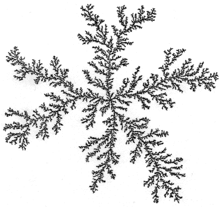
These patterns are examples of complex patterns obtained from simple deterministic evolution rules, and are also analytically tractable. Here complexity means that we have structures with variations, and a complete description of which is long. Thus, a living organism is complex because it has many different working parts, each formed by variations in the working out of the same, but relatively much simpler genetic coding. There are some earlier known theoretical examples of complex patterns obtained from local deterministic evolution rules. Most studied among them are the Conway’s game of life [earlierone], which is a cellular automata model with local update rules, and Turing patterns [earliertwo], which are reaction-diffusion models. In general, a detailed and exact mathematical characterization of such patterns has not been possible so far. In this aspect the sandpile patterns are important as they are analytically tractable. Understanding these should also help in studying the more general problem. The most important aspect of these patterns is that, these are the simplest examples that show nontrivial spatial features with proportionate growth (see Fig. 4.2), where these features grows in proportion, keeping the overall shape same. Examples of proportionate growth are abundant in the animal kingdom, where a young animal, typically, grows in size with time, with different parts of the body growing roughly at the same rate. Obviously, this kind of growth requires some coordination and communication between different parts. While there are many models of growing objects studied in physics literature so far, e.g. the Eden model, Diffusion-Limited Aggregation (DLA), invasion-percolation etc. [herrmann], none has this property. All of these are mainly models of aggregation, where growth occurs by accretion on the surface of the object, and inner parts do not evolve significantly (Fig. 4.3). It is worth mentioning, that modelling proportionate growth with simple structures is easy, e. g., growth of a water droplet as one injects more water into it. However, generating a complex pattern with large number of structures inside, all growing at same rate, maintaining their relative shape, is highly nontrivial. This is what happens in the patterns produced in the sandpile models.
Also, there is an astonishing qualitative similarity between the formation of these patterns and the way a fertilized egg develops into a well structured multicellular organism. The development starts with a single cell which divides into more cells, and then they divide in turn. At some stage of the development, few cells generate newer types of cells and form organs. This process continues and after a long time it forms a large complex, but highly coordinated cellular assembly. The same genetic code in each cell is responsible for the cell differentiation and structure formation. In the abelian sandpile when the sand grains are added at the same site, the grains redistribute themselves and a pattern emerges around the addition site, which grows as more and more sands are added. The same redistribution rule is used for all sites, and yet the pattern has large visibly distinguishable structures inside, which, one can think of as different organs in an animal. This simple mathematical model of growing sandpile captures these qualitative features, even though the actual mechanism of growth is much more complicated in the biological world.
The spatial patterns in sandpile models were first discussed by Liu et al. [liu]. The asymptotic shape of the boundaries of the sandpile patterns produced by adding grains at a single site in different periodic backgrounds was discussed in [dhar99]. Borgne et al. [borgne] obtained bounds on the rate of growth of these boundaries and later these bounds were improved by Fey et al. [redig] and Levine et al. [lionel]. The first detailed analysis of different periodic structures found in the patterns were carried out by Ostojic in [ostojic]. Other spatial configurations in the abelian sandpile models, like the identity [borgne, identity, caracciolo] or the stable state produced from special unstable states, also show complex internal self-similar structures [liu], which share common features with the patterns studied here. In particular, the identity configuration on the F-lattice has recently been shown to have spatial structure similar to what we study here [caracciolo]. There are other models, which are related to the abelian sandpile model, e.g. the Internal Diffusion-Limited Aggregation (IDLA), Eulerian walkers (also called the rotor-router model), and the infinitely-divisible sandpile, which also show similar structure. For the IDLA, Gravner and Quastel showed that the asymptotic shape of the growth pattern is related to the classical Stefan problem in hydrodynamics, and determined the exact radius of the pattern with a single point source [gravner]. Levine and Peres have studied patterns with multiple sources in these models recently, and proved the existence of a limit shape[levine_peres].
4.2 Definition of the model
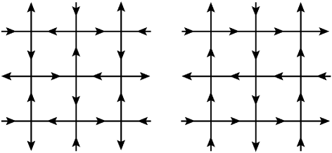
The pattern on a standard square lattice is rather complicated (Fig.4.1), and it has not been possible to characterize it so far. In this chapter, we consider two variations of the square lattice, assigning orientations to its edges, such that each site has two inward and two outward arrows, as shown in Fig.4.4a and Fig.4.4b. They are known as F-lattice and Manhattan lattice, respectively.
We define a position vector on the lattice, . The DASM is defined on the lattice by a height variable , at each site . In a stable configuration all sites have height . The system is driven by adding grains at a single site and if this addition makes the system unstable it relaxes by the toppling rule: each unstable site transfers one grain each in the direction of its outward arrows. We start with an initial checkerboard configuration in which for sites with even, and otherwise. Clearly, the average density of sand grains for the initial configuration is per site. For numerical purpose we use a lattice large enough so that none of the avalanches reaches the boundary. The result of adding grains at the origin is shown in Fig. 4.5 and Fig. 4.6, for the two lattices.
The asymptotic pattern in large limit, for the two lattices are indistinguishable from each other, at large scales, except that the thin lines of ’s forming two triangles outside the octagon are rotated by (Fig.4.6). Since the lattices are different, this is quite intriguing. Specially there is no obvious lattice symmetry, and it is easily checked that patterns produced for small are quite different (Fig.4.7).
This pattern is somewhat simpler than in Fig.4.1, which makes its study easier. We shall discuss here only the F-lattice, but the discussion is equally applicable to the Manhattan lattice. Taking some qualitative features of the observed pattern (e.g. only two types of patches are present, and they are all - or - sided polygons) as input, we show how one can get a complete and quantitative characterization of the pattern. We also show that the asymptotic pattern has an unexpected exact -fold rotational symmetry, and determine the exact coordinates of all the boundaries in it. We will also discuss some other cases, where exactly the same asymptotic pattern is obtained.
4.3 Characterizing asymptotic pattern: A general theory
We first describe a general method of formally characterizing a large number of sandpile patterns, not just the three patterns shown till now. We start by defining as the diameter of the pattern when grains have been added. The exact definition of is flexible, and the characterization does not depend on the choice. For the patterns in Fig. 4.1, 4.5, and 4.6 we choose as the width of the smallest rectangle that encloses all sites that have toppled at least once.
As mentioned before, the patterns exhibit proportionate growth, i.e., all structures in the pattern grows at the same rate to the diameter. While there is as yet no rigorous proof of this important property, we assume this in the following discussion. Then, it is natural to describe the patterns in the reduced coordinates defined by and . A position vector in these reduced coordinates is defined by . Then in the limit , the patterns can be characterized by a function which gives the local density of sand grains in a small rectangle of size about the point , with , . We define as the change in density from its initial background value.
A large number of sandpile patterns, including the one in Fig. 4.1, 4.5, and 4.6, are made of a union of distinct regions, called “Patches”, inside which the heights are periodic in space. Then, inside each patch is constant. For example, in the pattern in Fig. 4.5, there are only two types of patches, and the change in density takes only two possible values, in a high-density patch (color yellow in Fig. 4.5) and in a low-density patch (color orange). There are few defect-lines, which move with , and can also be seen in Fig.4.1 and Fig.4.5. But these can be ignored in discussing the asymptotic pattern.
Let be the number of topplings at site the when the diameter reaches the value for the first time. Define
| (4.1) |
where , with being the floor function which gives the largest integer . From the conservation of sand-grains in the toppling process, it is easy to see that
| (4.2) |
where the sum is over the sites nearest neighbors of , and is the number of them. Then in the rescales coordinate, satisfies the Poisson equation
| (4.3) |
In an electrostatic analogy, we can think of as an areal charge density, and as the corresponding electrostatic potential. A complete specification of determines the density function which in turn characterizes the asymptotic pattern.
The key observation that allows us to determine the asymptotic pattern is the following proposition.
Proposition 4.3.1
Inside each patch of periodic heights, is a quadratic function of and .
A proof can be done in the following way. Within a patch, the function is Taylor expandable around any point inside the patch.
| (4.4) |
where and . Consider any term of order in the expansion, for example the term . This can only arise due to a term in . Then, considering the fact that is an integer function of the coordinates, it is easy to see that it will change discontinuously at intervals of . This leads to change in the periodicity of heights at such intervals inside each patch which themselves are of size . This would then result in an infinitely many defect-lines in the asymptotic pattern. However there are no such features in Fig.4.1 or Fig.4.5. Therefore inside each periodic patch of constant , can at most be quadratic in and .
The argument finally boils down to proving the two features of the pattern, i.e., there is proportionate growth, and that the pattern can be decomposed in terms of periodic patches.
In each periodic patch the toppling function is a sum of two terms: a part, that is a simple quadratic function of and , and another is a periodic part. The periodic part averages to zero, and does not contribute to the coarse-grained function 222In some patterns, with other backgrounds (not discussed here) there are regions that occupy finite fraction area of the full pattern, which show aperiodic height patterns. These cases are harder to analyse.. The quadratic part, when rescaled, can be written as
| (4.5) |
where are constants inside a patch, and , corresponding to the patch. Then each patch is characterized by the values of these parameters.
Now we will show that the continuity of and its first derivatives along the boundary between adjacent patches imposes linear relations among the corresponding parameters. Consider two neighboring periodic patches and with mean densities and respectively. Let the rescaled quadratic toppling function be and in these patches. Then the boundary between the patches is given by the equation . As the derivatives of are also continuous across the boundary, the boundary between two periodic patches must be a straight line, and
| (4.6) |
where is the perpendicular distance of from the boundary. We can start with a periodic patch , and go to another patch by more than one path. Since the final quadratic function at should be the same whichever path we take, this imposes consistency conditions which restrict the allowed values of slopes of the boundaries. Consider a point where periodic patches meet, with (Fig.4.8). If the th boundary at this point makes an angle with the -axis, and the density of the patch in the wedge is (Fig.4.8), then the condition that the net change in the quadratic form is zero if we go around once, reduces to the following condition:
| (4.7) |
with . For , with , this equation has only trivial solutions with equal to or for all . Hence, only are allowed.
These linear equations amongst the parameters corresponding to neighboring patches, can be solved and this will determine the complete potential function , giving a quantitative characterization of the pattern.
4.4 Determination of the potential function
We now apply this method, in the last section, to the F-lattice pattern in Fig. 4.5, and determine the exact potential function . We note that in this pattern, there are no aperiodic patches, only two types of periodic patches, where only takes values or . Also, the slopes of the boundaries between patches only take values , or . The patches are typically dart shaped quadrilaterals, and some triangles. These simplifications, not present in Fig.4.1, make possible a full characterization of the pattern in Fig.4.5.
We start by determining the exact asymptotic size of the pattern. We note from Fig.4.5 that the boundary of the pattern is an octagon (we shall prove later that this is a regular octagon). In fact, there are four lines of ’s outside the octagon. But these have zero areal density in the limit , and do not contribute to . We will ignore these in the following discussion.
Let be the minimum boundary square containing all () that have a non-zero charge density . We observe that can be considered as a union of disjoint smaller squares, each of which is divided by diagonal into two parts where takes values and (Fig.4.9). This is seen to be true for the outer layer patches. Towards the center, the squares are not so well resolved. Assuming that this construction remains true all the way to the center, in the limit of large , the mean density of negative charge in the bounding square . Given that the total amount of negative charge is , the area of the bounding square should be . Hence, the boundaries of the minimum bounding square are
| (4.8) |
This means, with our choice of the diameter as the width of the box , we have
| (4.9) |
In Fig. 4.11, we have shown, the correction term appears to grow as .
Most of the time the avalanches does not reach the boundary. They are often stopped by the defect-lines inside the patches, which breaks the periodicity of the heights. For example, there are lines of alternating ’s and ’s inside the dense (all ) patches. When an avalanche enters the patch, the defect line shifts its position, partially increasing the size of the patch. An example of such event is shown in the Fig.4.10. Because of this, the diameter increases in steps with the increase of (see Fig.4.12).
Let be the minimum number of particles that have to be added so that at least one site at topples. We find that for , , , and , , , and . This is consistent with Eq. (4.9).
Then, the Poisson equation, in Eq. (4.3), for this pattern becomes,
| (4.10) |
i.e., there is unit amount of point charge at the origin.
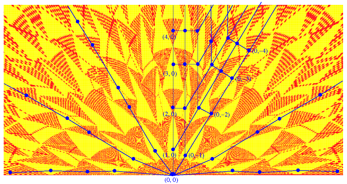
We now determine the parameters in the quadratic form of the potential function. In order to do that in a consistent way, we first look at the topological structure of the pattern. We note that the patches become smaller, and there are more of them in number, as we move towards the center. One can use a coordinate transformation , to avoid this overcrowding (Fig.4.13). We can now draw the adjacency graph (Fig.4.15) of the pattern, where each vertex denotes a patch, and a bond between the vertices is drawn if the vertices share a common boundary. It is convenient to think of the triangular patches in the pattern as degenerate quadrilaterals, with one side of length zero. Then we see that the adjacency graph is planar with each vertex of degree four, except a single vertex of coordination number eight corresponding to the exterior of the pattern. The graph has the structure of a square lattice wedge of wedge angle . The square lattice structure of the adjacency graph is seen more clearly, if rather than transformation, the transformation used is ( this has been used earlier in [ostojic]), where , and view it in the complex -plane (see Fig.4.14). Thus, one can equivalently represent the graph as a square grid on a Riemann surface of two sheets (fig.4.15).
We now use the qualitative information obtained from the adjacency matrix of the observed pattern, to obtain quantitative prediction of the exact coordinates of all the patches. Consider an arbitrary patch , having an excess density . The potential function in this patch is a quadratic function of and we parametrize it as
| (4.11) | |||||
The potential function in another patch having zero excess density is parametrized as
| (4.12) |
Now consider two neighboring patches and with excess densities and respectively. Then using the matching conditions (see Eq. (4.6)), it is easy to show that if the boundary between them is a horizontal line , we must have
| (4.13) |
There are similar conditions for other boundaries. These result a coupled set of linear equations for the coefficients . The equations for and do not involve other variables. In the outermost patch, clearly , and for this patch both and are zero. It follows that and are integers, equal to the Cartesian coordinates of the vertex corresponding to the patch in the discretized Riemann surface in Fig.4.15b. In the following, we denote a patch by integers , and write the corresponding coefficients , , and as , and . With this convention, the matching conditions in Eq.(4.13) can be rewritten as
| (4.14) |
Using similar matching conditions for the boundary of patch , with slope , we get the conditions
| (4.15) |
We can eliminate the variables and with even using Eq. (4.14) and Eq.(4.15). Then the equations become
| (4.16) | |||||
| (4.17) | |||||
| (4.18) | |||||
| (4.19) |
It is convenient to introduce the complex variables , and . In these variables we can write the potential function, in Eq. (4.11) and (4.12), as
| (4.20) |
where overbar denotes complex conjugation.
On the lattice, with odd, the natural basis vectors are and . Let us call these and . We define the finite difference operators and by
| (4.21) |
Then the equations (4.16-4.19) can be written as
| (4.22) |
These equations are the discrete analog of the familiar Cauchy-Riemann conditions connecting the partial derivatives of real and imaginary parts of an analytic function where the role of the analytic function is played by .
From Eq. and Eq.(4.19), it is easy to deduce that satisfies the discrete Laplace’s equation
| (4.23) |
If and are large, the corresponding patch is near the origin ( is small), and where the leading behavior of is given by (see Eq. 4.10). Consider a point , such that at
| (4.24) |
Then, would be expected to lie in the patch labeled by . This gives . Then, setting equal to gives us
| (4.25) |
The equation (4.23), subjected to the behavior at large given by Eq.(4.25) on the -wedge graph (for each value of , has two values) has a unique solution. Clearly the solution has eight fold rotational symmetry about the origin in the space. This implies that
| (4.26) |
Given , its real and imaginary parts determine and , and using Eq.(4.16, 4.17) we determine the exact positions of all the patch corners. The exact eight-fold rotational symmetry of the adjacency graph of the pattern, and the fact that satisfies Eq.(4.26) on the adjacency graph together imply the eight-fold rotational symmetry of all the distances in the pattern.
Note that for the usual square lattice, the solution of Eq.(4.23) is the well known 2-dimensional lattice Greens function, that is explicitly calculable for any finite , and is a simple polynomial of with rational coefficiants [spitzer]. However, for our case of the two sheeted Riemann surface, we have not been able to find a closed-form formula for . But the solution can be determined numerically to very good precision by solving it on a finite grid , with the condition in Eq.(4.25) imposed exactly at the boundary. We determined and numerically for , and extrapolated our results for . We find and , in perfect agreement with the exact theoretical values and , respectively, determined using the Fig. 4.9.
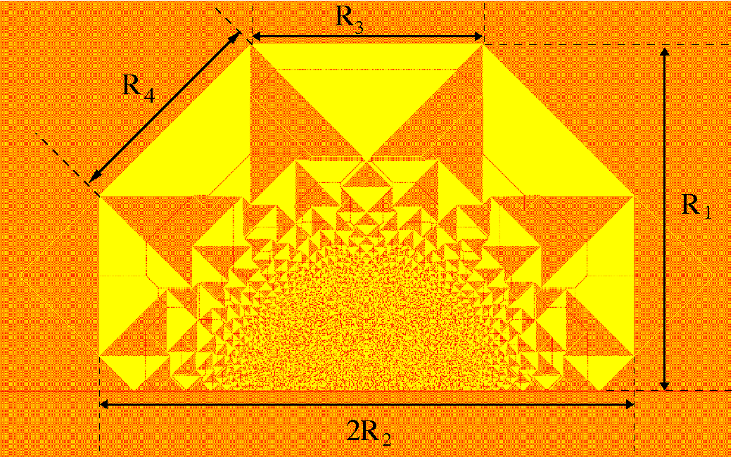

An interesting question to ask is, what is the size distribution of the patches? This can be easily determined from the transformation of the pattern, as shown in Fig.4.14. In this representation, the patches are positioned around the sites of the square grid, and all the patches have similar sizes. The Jacobian of the coordinate transformation is an estimate of the area on the - plane, corresponding to a unit area around site of the grid on the - plane. For large and , it can be shown that
| (4.27) |
On the other hand, from the same picture, the number of patches of area larger than or equal to the area of the patch is equal to the number of sites inside the circle of radius , on the square grid. This number increases linearly with . Then, the number of patches of area greater than or equal to is , which in turn implies that the number of patches of area lying between and would vary as .
4.5 Other patterns
Our calculations above can be easily extended to the patterns on any other background, on any other two dimensional lattices, so long as there are only patches with two values of . The matching conditions along the patch boundaries, ensure that the boundaries are straight lines. Although, we do not have a complete understanding of what determines the slope of the patch boundaries and the number of them for a patch, it seems, that as long as there are only two types of patches, the patches are always quadri-laterals, and the slopes of boundaries are integer multiples of . Then our analysis shows that the asymptotic pattern is same as the one for the F-latiice. For example, as mentioned already, this is true for the Manhattan lattice (Fig.4.6), for initial density . Same happens for the the F-lattice itself, with a different periodic background of initial density 5/8 ( if even, or congruent to , or , mod ). The pattern for this case is shown in (Fig.4.16). In this case, only the density of patches are different from the one on the checkerboard background, but the patch boundaries for the asymptotic pattern, in the rescaled coordinate, are at the identical positions.
In some other cases, like the F-lattice, with initially all sites empty, the pattern is very similar, but there are some aperiodic patches in the outermost ring (Fig.4.17). Since the behavior of in such patches are not known, the equations for do not close in this case.
Finally, how much of this analysis applies to the pattern in Fig. 4.1? As noted in [ostojic], there are large number, possibly infinitely many periodic patches in the asymptotic pattern. Characterization of such patterns remains an interesting open problem.
Chapter 5 Effect of multiple sources and sinks on the growing sandpile pattern
Based on the paper [myjsp2] by Tridib Sadhu and Deepak Dhar.
-
Abstract
In this chapter, we study the effect of sink sites on DASM patterns, discussed in chapter 4. Sinks change the scaling of the diameter of the pattern with the number of sand grains added. For example, in two dimensions, in the presence of a sink site, the diameter of the pattern grows as for large , whereas it grows as if there are no sink sites. In the presence of a line of sink sites, this rate reduces to . We determine the growth rates for various sink geometries along with the case when there are two lines of sink sites forming a wedge, and generalizations to higher dimensions. We characterize the asymptotic pattern in the large limit for one such case, the two-dimensional F-lattice with a single source adjacent to a line of sink sites. The characterization is done in terms of the positions of different spatial features in the pattern. For this lattice, we also provide an exact characterization of the pattern with two sources, when the line joining them is along one of the axes of the lattice.
5.1 Introduction
In the previous chapter, we studied growing sandpiles in the abelian model on the F-lattice and the Manhattan lattice. We were able to characterize the pattern corresponding to the initial configuration in which each alternate site of the lattice is occupied, forming a checkerboard pattern. The full characterization of this pattern reveals an interesting underlying mathematical structure, which seems to deserve further exploration. This is what we do in this chapter by adding sink sites or multiple sources.
The presence of sink sites changes the pattern in interesting ways. In particular, it changes how different spatial lengths in the pattern scale with the number of added grains . For example, in the absence of sink sites, the diameter of the pattern grows as for large , whereas in the presence of a single sink site, this changes to a growth. If there is a line of sink sites next to the site of addition, the growth rate is . We also study the case in which the source site is at the corner of a wedge-shaped region of wedge angle , where the wedge boundaries are absorbing. We show that for any the pattern grows as , with . This analysis is extended to other lattices with different initial height distributions, and to higher dimensions.
We also study the exact characterization of the asymptotic pattern in the infinite limit for the pattern with a line of sink sites. For a single point source, as discussed in chapter 4, the determination of the different distances in the pattern requires a solution of the Laplace equation on a discrete Riemann surface of two-sheets. Interestingly, for the pattern with a line sink, we still have to solve the discrete Laplace equation, but the structure of the Riemann surface changes from two-sheets to three-sheets.
We then study the effect on the pattern of having multiple sites of addition. For multiple sources, the pattern of small patches near each source is not substantially different from a single-source pattern, but some rearrangements occur in the larger outer patches. Two patches may sometimes join into one, or, conversely, a patch may break up into two. While the number of patches undergoing such changes is finite, the sizes and positions of all the patches are affected by the presence of the other source, and we show how these changes can be calculated exactly for the asymptotic pattern.
This chapter is organized as follows. In Section 5.2, we discuss scaling of the diameter of the patterns with for different sink geometries. First, we consider the pattern in the presence of a line of sink sites. Then, this analysis is extended to other sink geometries: two intersecting line sinks in two dimensions and two or three intersecting planes of sink sites in three dimensions. The problem of a single sink site is a bit different from the others, and is discussed separately in Section 5.3. In Section 5.4, we numerically verify the growth rates. The remaining sections are devoted to a detailed characterization of some of these patterns. In Section 5.5, we characterize the pattern in the presence of a line sink. In Section 5.6, we discuss the case when there are two sources present. These analytical calculations for the metric properties of the asymptotic pattern are compared in Section 5.7, with the measured values for the patterns with finite but large . Section 5.8, contains a summary and some concluding remarks.
5.2 Rate of growth of the patterns
For the single source pattern, discussed in chapter 4, the diameter , for large . We want to study how this dependence gets modified in the presence of sink sites.
First, consider the pattern formed by adding sand grains at a single site in the presence of a line of sink sites. In the rest of this chapter we will use the same notations defined in chapter 4. Any grain reaching a sink site gets absorbed, and is removed from the system. For simplicity let us consider the source site at and the sink sites along the -axis. A picture of the pattern produced by adding grains at is shown in Fig.5.1.
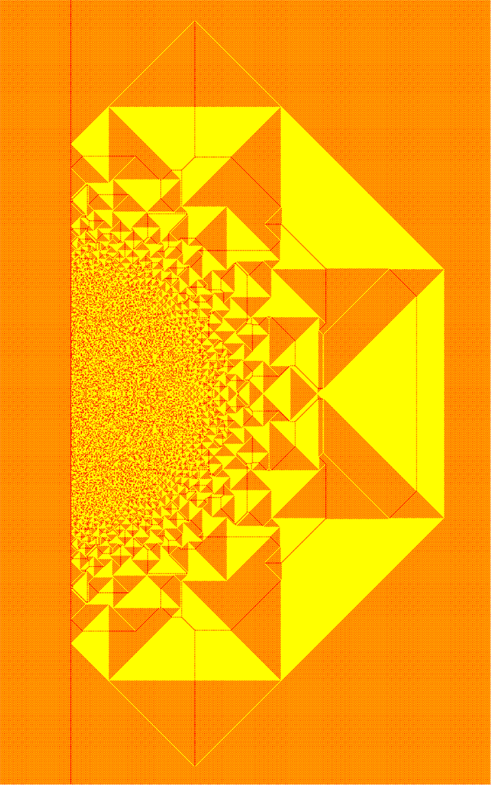
The equation analogous to Eq. (4.3) for this problem is
| (5.1) |
for all in the right-half plane with , where is the position of the source in reduced coordinates. Also, as there is no toppling at the sink sites, must satisfy the boundary condition
| (5.2) |
We can think of as the potential due to a point charge at and an areal charge density , in the presence of a grounded conducting line along the -axis. This problem can be solved using the well-known method of images in electrostatics. Let be the image point of with respect to the -axis. Define in the left half plane as
| (5.3) |
Then the Poisson equation for this new charge configuration is
| (5.4) |
As the function is odd under reflection, automatically vanishes along the -axis.
We define as the number of sand grains that remain unabsorbed. Then
| (5.5) |
where is the change in the height variables between its values before and after the system relaxes. Clearly, for large , we can write
| (5.6) |
where is the infinitesimal area around . The integration is performed over the right half-plane with . We shall use the sign to denote equality up to leading order in . Since is a non-negative bounded function, exactly zero outside a finite region, this integral exists. Let its value be , then we have
| (5.7) |
Let denote the number of grains that are absorbed by the sink sites. Then considering that the grains can reach the sink sites only by toppling at its neighbors we have
| (5.8) |
The factor comes from the fact that in the F-lattice, only half of the sites on the column would have arrows going out to the sink sites. Then using our scaling ansatz in equation (4.1), for large,
| (5.9) |
Hence
| (5.10) |
Now from equation (5.4) the potential can be written as the sum of two terms: due to two point charges and at and its image point respectively, and the term due to the areal charge density.
| (5.11) |
where
| (5.12) |
We first consider the case where is finite and vanishes in the large limit. Then reduces to a dipole potential, and it diverges near the origin. However, is a continuous and differentiable function for all . From the solution of the dipole potential, it is easy to show that
| (5.13) |
for , where we have used polar coordinates with being measured with respect to the -axis. Here is a numerical constant, which is a property of the asymptotic pattern. Then
| (5.14) |
and the integral in equation (5.10) diverges as , where is the cutoff introduced by the lattice. Using it is easy to show that
| (5.15) |
where is a constant. Then using equations (5.7) and (5.15) and that and add up to , we get
| (5.16) |
Considering the dominant term in the expression for large , it follows that increases as .
For the patterns in the other limit where the source is placed at a distance such that is non-zero for , is non-singular along the sink line. Then, clearly and as a result .
The above analysis can be easily generalized to a case with the sink sites along two straight lines intersecting at an angle and a point source inside the wedge. For a square lattice, and are most easily constructed, and avoid the problems of lines with irrational slopes, or rational numbers slopes with large denominators. The wedge with wedge-angle is obtained by placing the sink sites along the and -axis and the source site at in the first quadrant. The pattern with a line sink, discussed in previous section, corresponds to .
For the general , the corresponding electrostatic problem reduces to determining the potential function inside a wedge formed by two intersecting grounded conducting lines. Again the potential has two contributions: the potential due to a point charge at the source site and the potential due to the areal charge density. We first consider the case where the source site is placed at a finite distance from the wedge corner such that the distance in reduced coordinates vanishes in the large limit. In this limit is a non-singular function of while diverges close to the origin. A simple calculation of the electrostatic problem gives
| (5.17) |
where and we have used polar coordinates with the polar angle measured from one of the absorbing lines. Again is a constant independent of or and is a property of the asymptotic pattern. Then arguing as before, we get
| (5.18) |
So the equation analogous to equation (5.16) is
| (5.19) |
For a wedge angle , , and the above equation reduces to Eq.(5.16).
Similar arguments involving conformal transformation have been used earlier in the context of equilibrium statistical physics to determine the wedge-angle dependence of surface critical exponents near a wedge [dup].
For the problem where the source site is at a distance from the wedge corner both the functions and are nonsingular close to the origin. It is easy to show that grows as .
These arguments can be easily extended to other lattices with different initial height distributions, or to higher dimensions. Consider, for example, an abelian sandpile model defined on the cubic lattice. The allowed heights are from to , and a site topples if the height exceeds , and sends one particle to each neighbor. The sites are labelled by the Cartesian coordinates , where and are integers. We consider the infinite octant defined by . We start with all heights equal to , and add sand grains at the site . We assume that the sites on planes , and are all sink sites, and any grain reaching there is lost. We add grains and determine the diameter of the resulting stable pattern.
We again write the potential function in two parts: due to a point charge at and due to the bulk charge density in the presence of three conducting grounded planes. Then, a simple electrostatic calculation shows that the potential is the octapolar potential with it’s form in spherical polar coordinate as
| (5.20) |
This then implies that the equation determining the dependence of on is
| (5.21) |
5.3 A single sink site
Let the site of addition be the origin, with the sink site placed at . We shall show that when lies in a high-density patch (color yellow in Fig.5.2), the asymptotic patterns are identical to the one produced in the absence of the sink site.
The patterns, produced for close to , with the sink sites placed deep inside a high-density patch are simple to analyze, even for finite but large . One such pattern is presented in Fig.5.2.
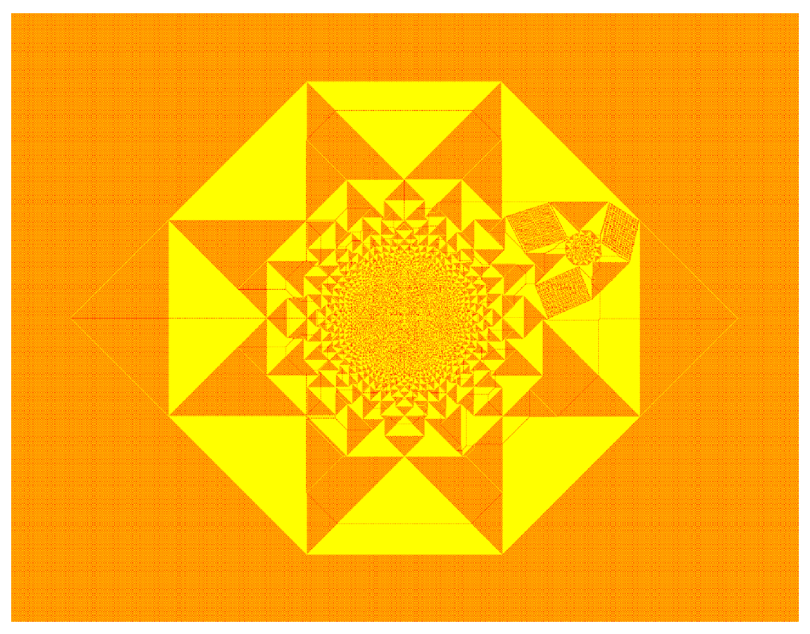
We see that the effect of the sink site on the pattern is to produce a depletion pattern centered at this site. The depletion pattern is a smaller negative copy of the single source pattern, where negative means is negative of the original pattern. We define the function as the difference between the heights at in the final stable configuration produced by adding grains at the origin, with and without the sink site.
| (5.22) |
From the figure it is seen that, in this case, is the negative of the pattern produced by a smaller source, centered at . The number of grains required to produce this smaller pattern is exactly the number of grains absorbed at the sink site.
| (5.23) |
This is immediately seen from the fact that the toppling function satisfies
| (5.24) |
where is the toppling matrix for the sandple model on the F-lattice (see chapter 3). Let be the number of topplings at , when we add particles at the origin in the absense of any sink site. Since Eq. (5.24) is a linear equation, it follows that a solution of this equation is
| (5.25) |
This is a valid solution for our problem, if the corresponding heights in the final configuration with the sink are all non-negative. This happens when the region with nonzero is confined within a high-density patch of the single source pattern.
The number can be determined from the requirement that the number of topplings at the sink site is zero. The potential function for the single source problem diverges as near the source. Considering the ultraviolate cutoff due to the lattice, at can be approximated by to leading order in . Then at , is approximately equal to whereas , where is the potential function for the problem without a sink. Then from the equation (5.25) we have
| (5.26) |
For large , this implies that
| (5.27) |
Then, in the large limit, for a sink at a fixed reduced coordinate , the relative size of the defect produced by the sink site decreases as . Hence asymptotically, the fractional area of the defect region will decrease to zero, if the sink position is inside a high-density patch.
When the sink site is inside a low-density patch, the subtraction procedure in equation (5.23) gives negative heights, and no longer gives the correct solution. However it is observed for the patches in the outer layer, where the patches are large, that the effect of the sink site is confined within the neighboring high-density patches (Fig.5.3) and rest of the pattern in the asymptotic limit remains unaffected.
The pattern in which the source and the sink sites are adjacent to each other, appears to be very similar to the one produced without the sink site. This is easy to see. The Poisson equation analogous to equation (4.3) for this problem is
| (5.28) |
where is the number of grains absorbed in the sink site at . In an electrostatic analogy, as discussed earlier, can be considered as the potential due to a distributed charge of density and two point charges of strength and , placed at the origin and at respectively. It is easy to see that the dominant contribution to the potential is the monopole term with net charge . The contribution due to other terms decreases as for large , and the asymptotic pattern is the same as without a sink, with particles added.
The number of particles absorbed is determined by the condition that the number of topplings at (the sink position) is zero. The potential produced at and , by the areal charge density is nearly the same. The number of topplings at , if we add particles at the sink site, is approximately . Now, from the solution of the discrete Laplacian, the number of topplings produced at due to particles added at is approximately with being an undetermined constant. Equating these two, we get
| (5.29) |
As the asymptotic pattern is the same as that produced by adding grains at the origin without a sink, we have , and
| (5.30) |
Simplification of this equation for large shows that grows as with .
For finite , the leading correction to comes from the dipole term in the potential. This term breaks the reflection symmetry of the pattern about the origin. A measure of the bilateral asymmetry is the difference of the boundary distances on two opposite sides of the source. As the relative contribution of the dipole potential compared to the monopole term decays as , for large , this difference vanishes in the asymptotic pattern in the reduced coordinates.
5.4 Numerical results
All the above scaling behaviors are verified by the measurement of lengths in the patterns for finite, but large . Let be the real positive root of equation (5.16) for a given integer value of . As takes only the integer values on the lattice, an estimate of it would be , the integer nearest to . Interestingly, we found that for a choice of and , this estimate gives values which differ from the measured values at most by for all in the range of to . We rewrite the equation (5.16) as
| (5.31) |
where we used the symbol to denote that both sides differ at most by . Clearly more precise estimates of and would be required if we want this to work for larger .
Similarly for the other two equations (5.19) and (5.21) we find that they are in very good agreement with our numerical data. We consider the case of wedge angle . This corresponds to the case with the source site next to an infinite half-line of sink sites. Here and equation (5.19) reduces to
| (5.32) |
Choosing and , we find that the function differs from the measured values by at most for all in the range of to . Then, as in equation (5.31), we write
| (5.33) |
Similarly, for the three dimensional abelian sandpile model with the source site inside the first octant and , , and as the absorbing planes, the equation determining the dependence of the diameter on is
| (5.34) |
We have verified this equation for between to .
We obtained these equations by determining the number of absorbed grains and the remaining grains from dimensional counting grounds, and the final equations are then only a statement of the conservation of the sand grains. It is quite remarkable that this scaling analysis gives almost the exact values of the diameter. In addition, these equations have an important feature that they include a “correction to scaling” term whereas the usual scaling analysis ignores the sub-leading powers.
We also verify equation (5.27) using patterns with fixed and the sink site inside a high-density patch in the outer layer of the pattern. It is found that for a change of from to , changes by less than , which is consistent with the scaling relation.
In the other limit, where the sink site is next to the source, the dependence of on is given in equation (5.30). We measure for the patterns with the sink site at and the source at the origin. For in the range of to we find that the function with in equation (5.30), gives almost exact values of , with their difference being at most . Then we write
| (5.35) |
In the last case, let and be the boundary distances measured along the positive and the negative axis. The difference is plotted in Fig.5.4 where the data is found to fit to the function . This confirms the result that the relative bilateral asymmetry vanishes in the asymptotic pattern as .
5.5 Characterization of the pattern with a line sink
The pattern with a line sink (Fig.5.1), discussed in Section 5.2, retained two important properties present in the single source pattern (Fig. 4.5). These are: The asymptotic pattern is made of the union of two types of patches of excess density and and the separating boundaries of the patches are straight lines of slope , or . However the adjacency graph is changed significantly and this changes the sizes of the patches as well. In this section we show how to explicitly determine the potential function on this adjacency graph.
The adjacency graph of the patches is shown in Fig.5.6. This representation of the graph is easier to see by taking the transformation of the pattern and then joining neighboring patches by straight lines (Fig.5.5). Each vertex in the graph is connected to four neighbors except for the vertices corresponding to the patches next to the absorbing line. These have coordination number . Also the vertex at the center corresponding to the exterior of the pattern is connected to seven neighbors.
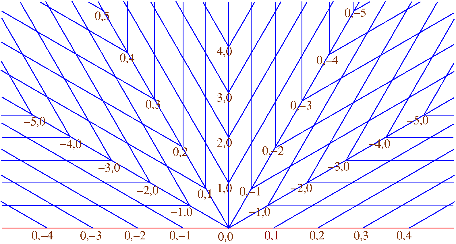
Let us write the quadratic potential function in a patch having excess density as
| (5.36) |
where the parameters , , , and take constant values within a patch. Similarly for a low-density patch
| (5.37) |
Using the continuity of and its first derivatives along the common boundaries between neighboring patches it has been shown in chapter 4, that for the single source pattern without sink sites , and take integer values. The same argument also applies to this problem and it can be shown that are the coordinates of the patches in the adjacency graph in Fig.5.6. These coordinates are shown next to some of the vertices. There are two different patches corresponding to the same set of values. In fact, as in the single source pattern the adjacency graph forms a square grid on a two sheeted Riemann surface, the same is formed for this pattern, but on a three sheeted Riemann surface. This can be constructed by modifying the graph in Fig 5.6 keeping its topology the same. In this representation the pattern covers half of the surface with being the Cartesian coordinates on the surface.
Define function on this lattice. As discussed in [myepl], the continuity of and its first derivatives along the common boundary between neighboring patches imposes linear relations between and of the corresponding patches. Using these matching conditions it can be shown that and satisfy the discrete Cauchy-Riemann conditions [myepl]
| (5.38) |
and then the function satisfies the discrete Laplace equation
| (5.39) |
on this adjacency graph.
Let us define and . As argued before, close to the origin the potential diverges as (equation (5.13)). Then, the corresponding complex potential function . As , and , it follows that for large ,
| (5.40) |
Also, the condition that on the absorbing line must vanish implies that for the vertices with even along the red line in Fig.5.6 vanishes. These vertices correspond to the patches with the absorbing line as the horizontal boundary in Fig.5.1.
Equation (6.19) with the above constraint and the boundary condition (Eq.(5.40)) has a unique solution. The normalization of is fixed by the requirement that , which fixes the diameter of the pattern to be in reduced units. All the spatial distances in the pattern can be expressed in terms of this solution using the matching conditions between two neighboring patches. As an example, consider the boundary between the patches corresponding to and with being odd. The matching conditions only allow a horizontal boundary between them with the equation , where
| (5.41) |
Similarly there is a vertical boundary between the patches and , with the equation , where
| (5.42) |
The other boundaries can similarly be determined using the solution for . The characterization of the asymptotic patterns for , and is qualitatively similar and will not be discussed here.
5.6 Patterns with two sources
In this section we discuss patterns produced by adding grains each at two sites placed at a distance from each other along the -axis, at and with . Again, the diameter is defined as the height of the smallest rectangle enclosing all sites that have toppled at least once. The two limits, close to zero and large are trivial: For , the asymptotic pattern is the same as that produced by adding grains at a single site. On the other hand if , each source produces its own pattern, which do not overlap, and the final pattern is a simple superposition of the two patterns.
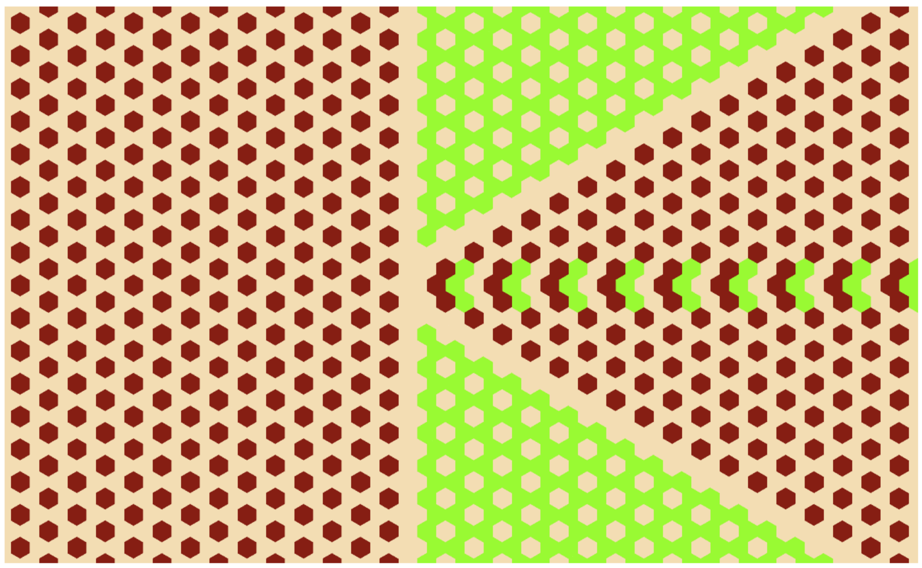
As noted before, the adjacency graph for the single source pattern has a square lattice structure on a Riemann surface of two-sheets [myepl]. Then the graph for two non-intersecting single source patterns is a square lattice on two disjoint Riemann surfaces, each having two-sheets (Fig.5.9). Only the vertex at the origin represents the exterior of the pattern, which is the same for both of the single source patterns. It has sixteen neighbors and is placed midway between the two Riemann surfaces. For later convenience let us associate the lower Riemann surface to the pattern around the left source at and denote it by . Similarly the upper Riemann surface as corresponding to the pattern around the right source .
For , the two single source patterns overlap. Using the abelian property, we first topple as if the second source were absent. The resulting pattern still has some unstable sites in the region where the patterns overlap. Further relaxing these sites transfers these excess grains outward, and changes the dimensions and positions of the patches: some patches become bigger, some may merge, and sometimes a patch may break into two disjoint patches.
The pattern produced with two sources with is shown in Fig.5.7. We see that there are still only two types of periodic patches, corresponding to values and , and the slope of the boundaries between patches takes the values , or .
The relaxation due to overlap changes the adjacency graph from the case with no overlap. This modified adjacency graph, for in the range to , is shown in Fig.5.10. For just below , these changes are few and are listed below.
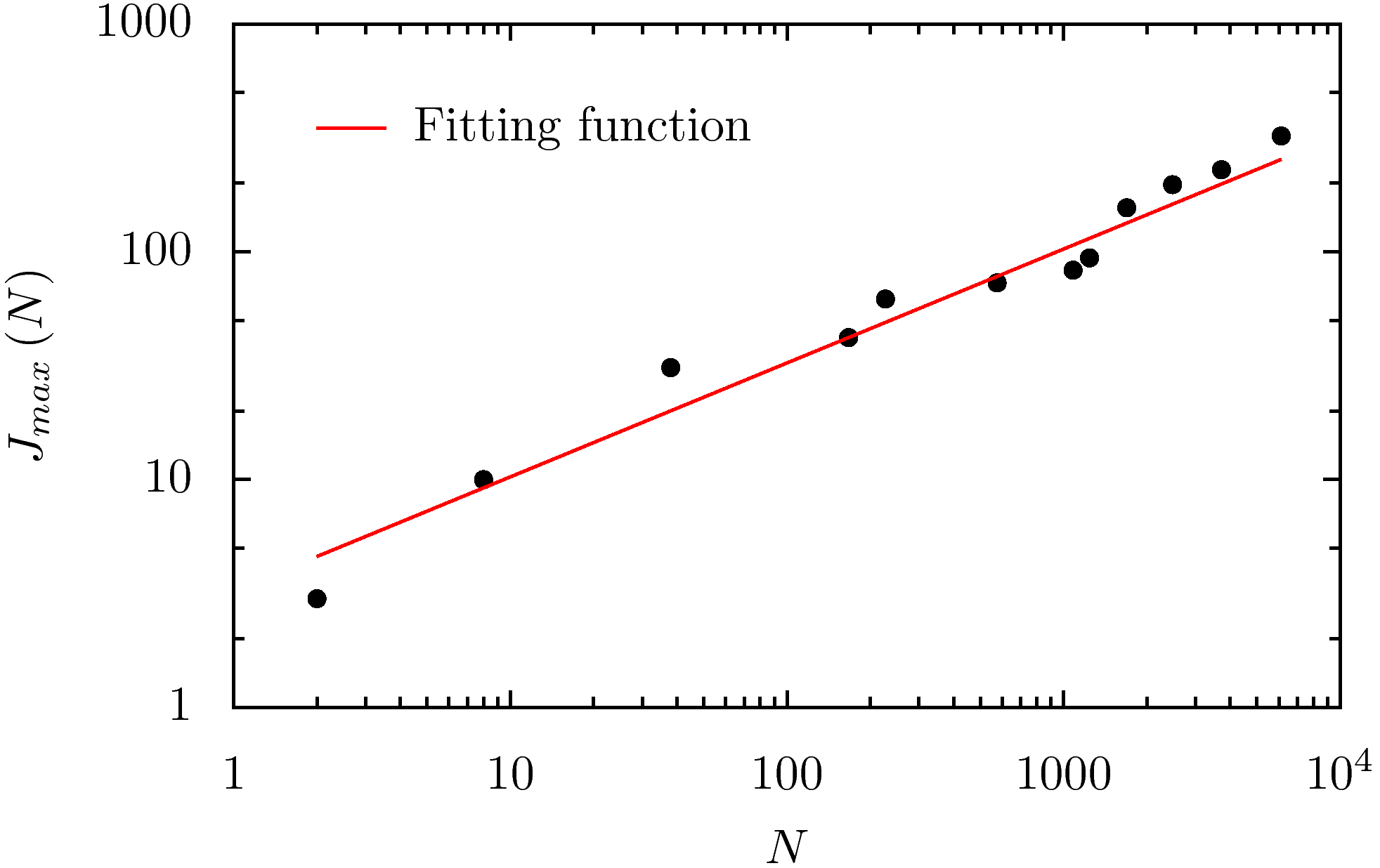
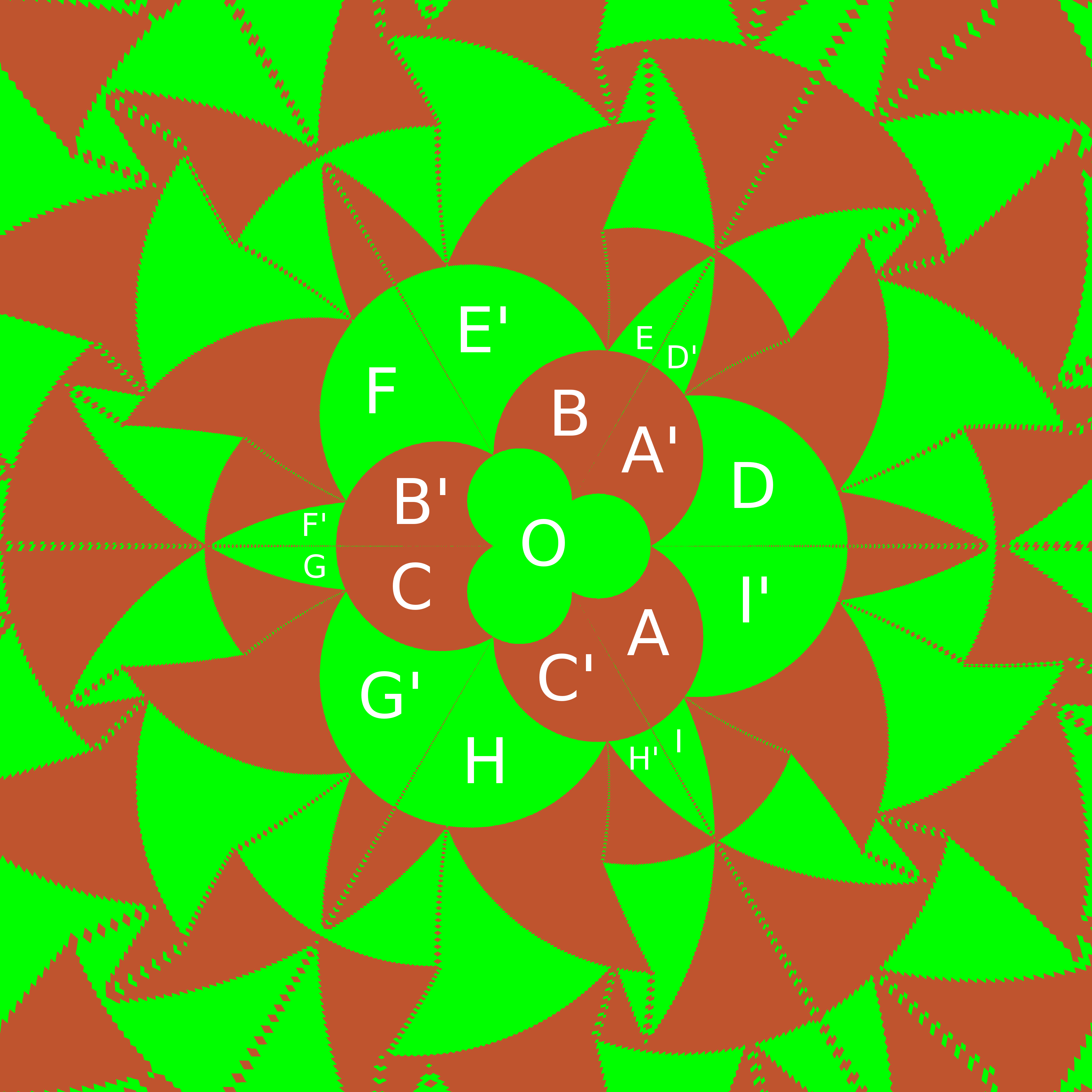
(i) We note that the patches labelled and in Fig.5.8 have the same and dependence of the potential function . Then, for just below , these patterns can join with each other by a thin strip. This only requires a small movement in the boundaries of nearby patches ( i.e. only a small change in the and values of nearby patches). Thus, in the adjacency graph, the vertices corresponding to and are collapsed into a single vertex in Fig.5.10.
(ii) Similarly, the vertices corresponding to the patches and in Fig.5.8 are collapsed into a single vertex in Fig.5.10.
(iii) This divides the region outside the pattern in to three parts, , and . They are also shown in Fig.5.10 as separate vertices.
(iv) The patches marked and also have the same quadratic form, and the vertical boundary between them disappears. However, the patches and are also joined by a thin strip. This horizontal strip divides the joined and into two again (Fig.5.8).
The adjacency of other patches remains unchanged. The adjacency graph of the pattern is shown in Fig.5.10. Interestingly, this new adjacency graph remains the same for all , even though for , the sizes of different patches are substantially different. Compare the pattern for in Fig.5.11, with the pattern for in Fig.5.7: The shape of the central patches in Fig.5.11 is different from that in Fig.5.7.
In Fig.5.10, we have have placed the vertices which are formed by merging or dividing the patches, midway between the Riemann sheets corresponding to the two sources. As is decreased below , more collisions between the growing patches will occur and the number of vertices in this middle region will increase. For any nonzero , the number of vertices in the middle layer is finite. In the limit, vertices from both the surfaces and come together and form a single Riemann surface corresponding to a single source pattern around . For small, but greater than zero, the outer patches are arranged as in the single-source case, but closer to the sources, one has a crowded pattern near each source. In the adjacency graph, this corresponds to the vertices near the patch roughly arranged as on a Riemann surface of two-sheets, while the ones farther from the patch remain undisturbed on the 4-sheeted Riemann surface.
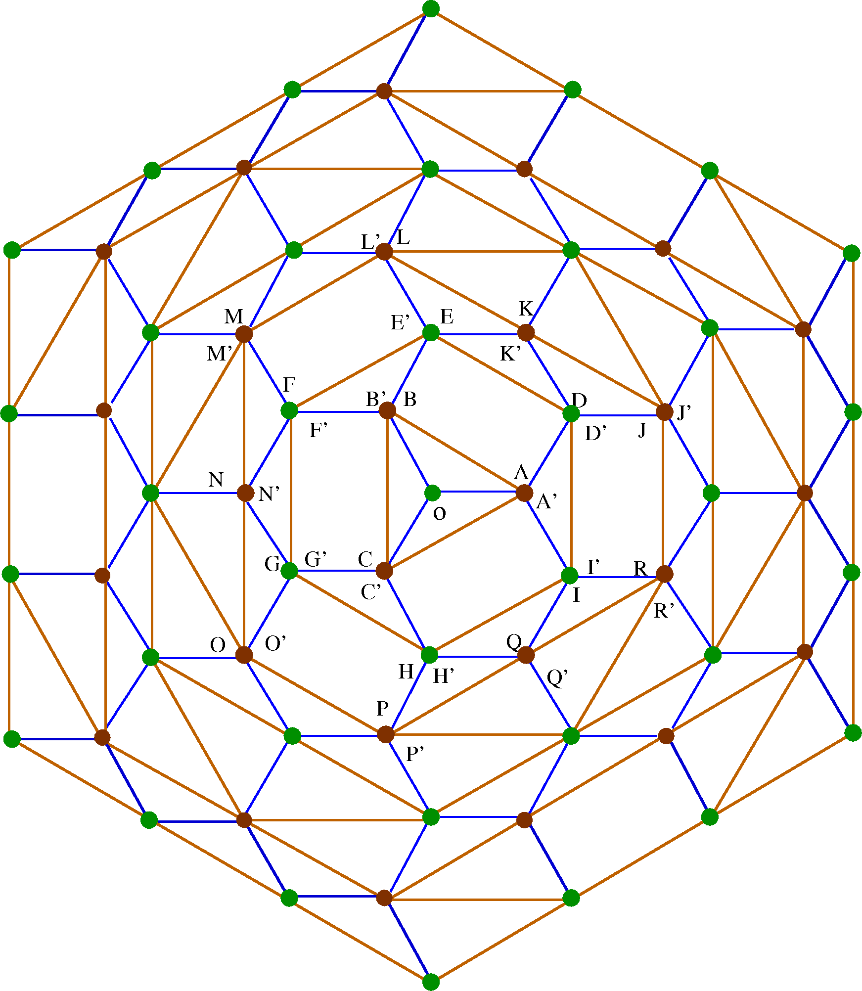
We now characterize the pattern with two sources and in detail by explicitly determining the potential function on this adjacency graph.
The Poisson equation analogous to Eq.(4.3) for this problem is
| (5.43) |
Let us use the same quadratic form of the potential function given in equation (5.36) and equation (5.37).
Again using the same argument given in [myepl], it can be shown that and are the coordinates of the patches in both the adjacency graphs in Figs.5.9 and 5.10. These coordinates are shown next to each vertex. Also, on this graph, the function satisfies the discrete Laplace equation
| (5.44) |
where denote the neighbors of in the odd or even sublattice [duffin]. Let us define where and are the coordinates corresponding to and . Considering that close to and the potential diverges logarithmically it can be shown (as done for single source pattern in [myepl]) that for large ,
| (5.45) | |||||
where is a constant independent of or . The solution of the equation (5.44) with the boundary condition and that in equation (5.45) for large determines the final pattern.
5.7 Numerical analysis
In both the examples in section and the patterns are characterized in terms of the solution of the standard two dimensional lattice Laplace equation on the corresponding adjacency graphs. The solution is well-known when [spitzer]. In our case where the lattice sites form surfaces of multiple sheets, we have not been able to find a closed-form expression for . However, the solutions can be determined numerically to very good precision by solving it on a finite grid with the corresponding boundary conditions imposed exactly at the boundary.
For the pattern with the line sink, the calculation is performed with at the boundary and then the solution is normalized to have . We determined and numerically for , , , and and extrapolated our results for . Comparison of the results from this numerical calculation and that obtained by measurements on the pattern is presented in Table . We consider the four different lengths , , and as defined in Fig.5.12. By the definition of the diameter of the pattern . We present the values of , and normalized by for different . The asymptotic values of these lengths are determined from the values of and . Comparison of these results shows very good agreement between the theoretical and the measured values.
| N | Theoretical | ||||
|---|---|---|---|---|---|
| 0.769 | 0.768 | 0.770 | 0.770 | 0.7698 | |
| 0.675 | 0.675 | 0.667 | 0.668 | 0.6666 | |
| 0.609 | 0.609 | 0.617 | 0.616 | 0.6172 |
A similar numerical calculation is done for the pattern with two sources. In this case the boundary condition is given by equation (5.45). The value of is determined from a self consistency condition that the diameter of the pattern in the reduced coordinate is which imposes corresponding to the vertex in Fig.5.10. We determined and numerically for , , , and and extrapolated our results for . A comparison of the results from this numerical calculation and that obtained by measurements on the pattern are presented in Table . We considered five different spatial lengths in the pattern, corresponding to . These different lengths are drawn in Fig.5.13 and their values rescaled by , for the patterns with increasing , are given in Table . The asymptotic values of these lengths are obtained using the values of and . The rescaled lengths extrapolated to the infinite limit match very well with the theoretical results.
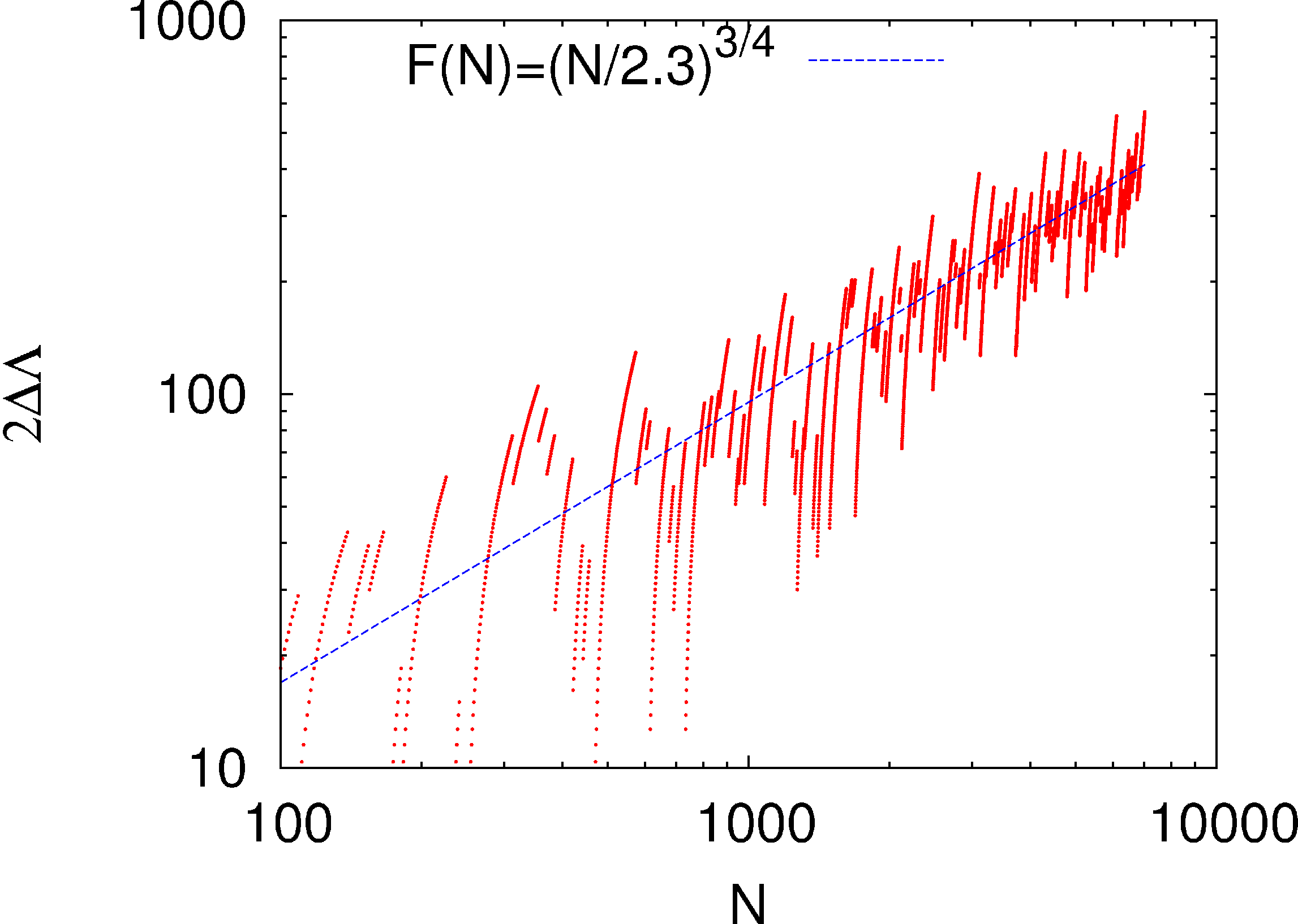
| N | Theoretical | |||||
|---|---|---|---|---|---|---|
| 1.84 | 1.84 | 1.84 | 1.83 | 1.83 | 1.82 | |
| 1.06 | 1.07 | 1.07 | 1.06 | 1.05 | 1.06 | |
| 0.22 | 0.21 | 0.20 | 0.19 | 0.18 | 0.18 | |
| 0.18 | 0.19 | 0.19 | 0.18 | 0.18 | 0.18 | |
| 0.20 | 0.22 | 0.21 | 0.21 | 0.21 | 0.21 |
5.8 Discussion
While the results discussed in quantifying the patterns with growing sandpiles are presumably exact (in the sense that can be determined to arbitrary precision), they have not been established rigorously. In particular, as noted before, it would be desirable to have a direct proof of the proportional growth property from the definition of the problem. Also, we use the observation that the asymptotic pattern consists of only two types of patches, and the adjacency graph of the pattern is also taken as observed. It would be nice to see it following from the definition of the problem. The unexpected accuracy of the scaling arguments giving Eqs. (, , , ) also deserves to be understood better.
We have shown that the exact characterization of the patterns in the F-lattice on a checkerboard background reduces to solving a discrete Laplace equation on the adjacency graph of the pattern. For the single source pattern this graph is a square grid on a two-sheeted Riemann surface and in the presence of a line sink it is on a three-sheeted Riemann surface. This Riemann surface structure occurs for other sink geometries as well and the number of sheets can be determined from the way diverges near the origin.
If the potential diverges as near the origin, then the corresponding complex function . Then . In all the cases studied above, the patch to which point belongs is characterized by integers , where . Also . Writing , and , we see that . This then gives the number of Riemann sheets. For example, for the wedge angle , we have . Then , and the Riemann surface would have 5 sheets.
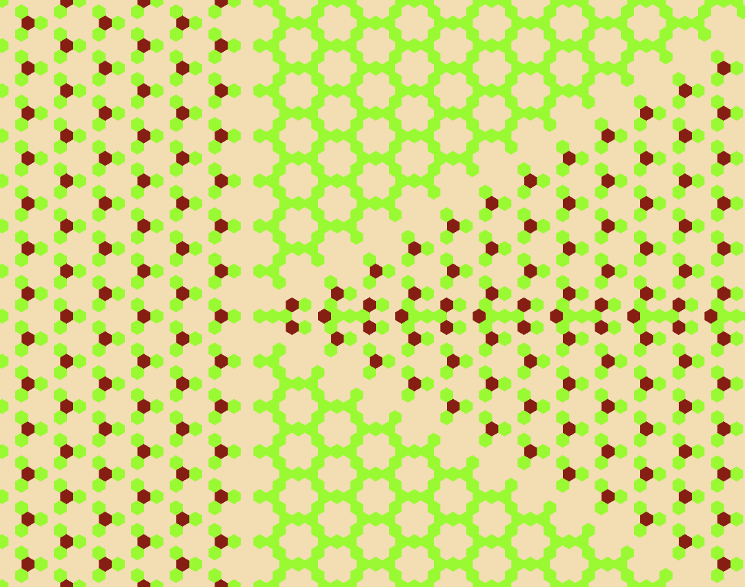
The patterns discussed so far in this chapter have only two types of patches with densities and . But it is possible to have patterns with patches of other densities. For example, for the patterns with two sources, even a slight deviation of the position of the second source in Fig.5.7 from the x-axis introduces patches which have areal density different from or . One such pattern produced by adding grains each at and is shown in Fig.5.14. The regions with stripes of red and yellow are patches of the new density. In addition, the boundaries of these patches have slopes other than , and . Most of the analysis presented here is appilcable to this pattern, except that the matching conditions along the common boundary between two patches and the adjacency graph are different.
The cases in which the full pattern can be explicitly determined are clearly special. For example, one of the conditions used for the exact characterization of the patterns in this chapter is that inside each patch the height variables are periodic and hence is constant. It is easy to check that this condition is not met for most sink geometries. For example, patterns of the type discussed in Section with any other than integer multiples of have aperiodic patches. In such cases, the present treatment for characterization of patterns is clearly not applicable. However, the scaling analysis for the growth of the spatial lengths in the pattern with is still valid.
The function satisfies the discrete Cauchy-Riemann condition (equation (5.38)). These functions are known as discrete holomorphic functions in the mathematics literature. Usually they have been studied for a square grid of points on the plane [duffin, spitzer]. While more general discretizations of the plane have been discussed [mercat, laszlo], not much is known about the behavior of such functions for multi-sheeted Riemann surfaces. A perturbative approach of determining these functions for square discretization of multi-sheeted Riemann surface is presented in the Appendix B.
In our analysis we have also used the fact that the patterns have nonzero average overall excess density ( i.e. in Eq. (5.7) is nonzero). The case is quite different, and requires a substantially different treatment. We discuss such patterns in the next chapter.
Chapter 6 Pattern Formation in Fast-Growing Sandpiles
Based on the paper [myjsm] by Tridib Sadhu and Deepak Dhar.
-
Abstract
We study the patterns formed by adding sand-grains at a single site on an initial periodic background in the Abelian sandpile models, and relaxing the configuration. When the heights at all sites in the initial background are low enough, one gets patterns showing proportionate growth, with the diameter of the pattern formed growing as for large , in -dimensions. On the other hand, if sites with maximum stable height in the starting configuration form an infinite cluster, we get avalanches that do not stop. In this chapter, we describe our unexpected finding of an interesting class of backgrounds in two dimensions, that show an intermediate behavior: For any , the avalanches are finite, but the diameter of the pattern increases as , for large , with . Different values of can be realized on different backgrounds, and the patterns still show proportionate growth. The non-compact nature of growth simplifies their analysis significantly. We characterize the asymptotic pattern exactly for one illustrative example with .
6.1 Introduction
In the last two chapters, we studied the patterns produced by adding grains at a single site in a Deterministic Abelian Sandpile Model (DASM), and relaxing. A complete relaxation process, starting from the addition of sand to reaching the final stable configuration is called an avalanche. The length of an avalanche depends on the initial height configuration, i e., the background. For some backgrounds on an infinite lattice, topplings may continue for ever, and the avalanches reach to infinity. For other backgrounds, where the avalanches are finite, the toppled sites form patterns in the spatial configuration of sites with different values of the height variables.
The backgrounds leading to infinite avalanches have been termed as explosive.
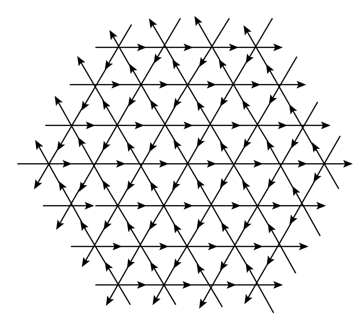
In the other backgrounds with finite avalanches the diameter of the pattern usually grows as with increasing number of added grains in dimensions. We call this type of growth as compact growth. All the patterns studied so far showed compact growth. In this chapter, we describe a remarkable class of patterns where the diameter remains finite for any finite , but grows as , with . We call this type of growth as non-compact growth. Characterization of these patterns, as will be shown, is simpler than the ones with compact growth.
For a sandpile model with stochastic toppling rule, the size of the pattern is determined only by the density of heights in the background, and the specific arrangement of heights does not matter. There exist a critical density , depending on the toppling rules, such that, on a background with sub-critical density , finite avalanches occur with probability . The corresponding asymptotic pattern is a simple circle, with density , inside, and the diameter of the circle growing as . For densities , probability of finite avalanches vanishes in the large limit.
For a deterministic sandpile a similar critical density can not be defined. One can construct backgrounds with densities very close to zero, and still there are infinite avalanches. A simple example of such backgrounds, on any lattice, is the one where the sites with height form an infinite connected cluster, with being the threshold height. Height at other sites could be zero, and thus the density of the background could be made very small. On the other hand, it is possible to construct backgrounds with mean density arbitrarily close to , and yet the avalanches are always finite LABEL:explosion. Absence of an infinite avalanche depends on the detailed arrangement of heights in the background, and not on the density alone.
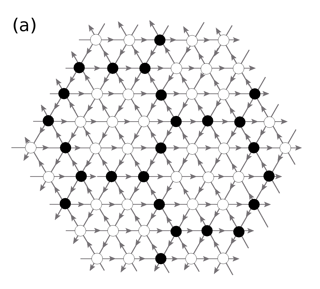
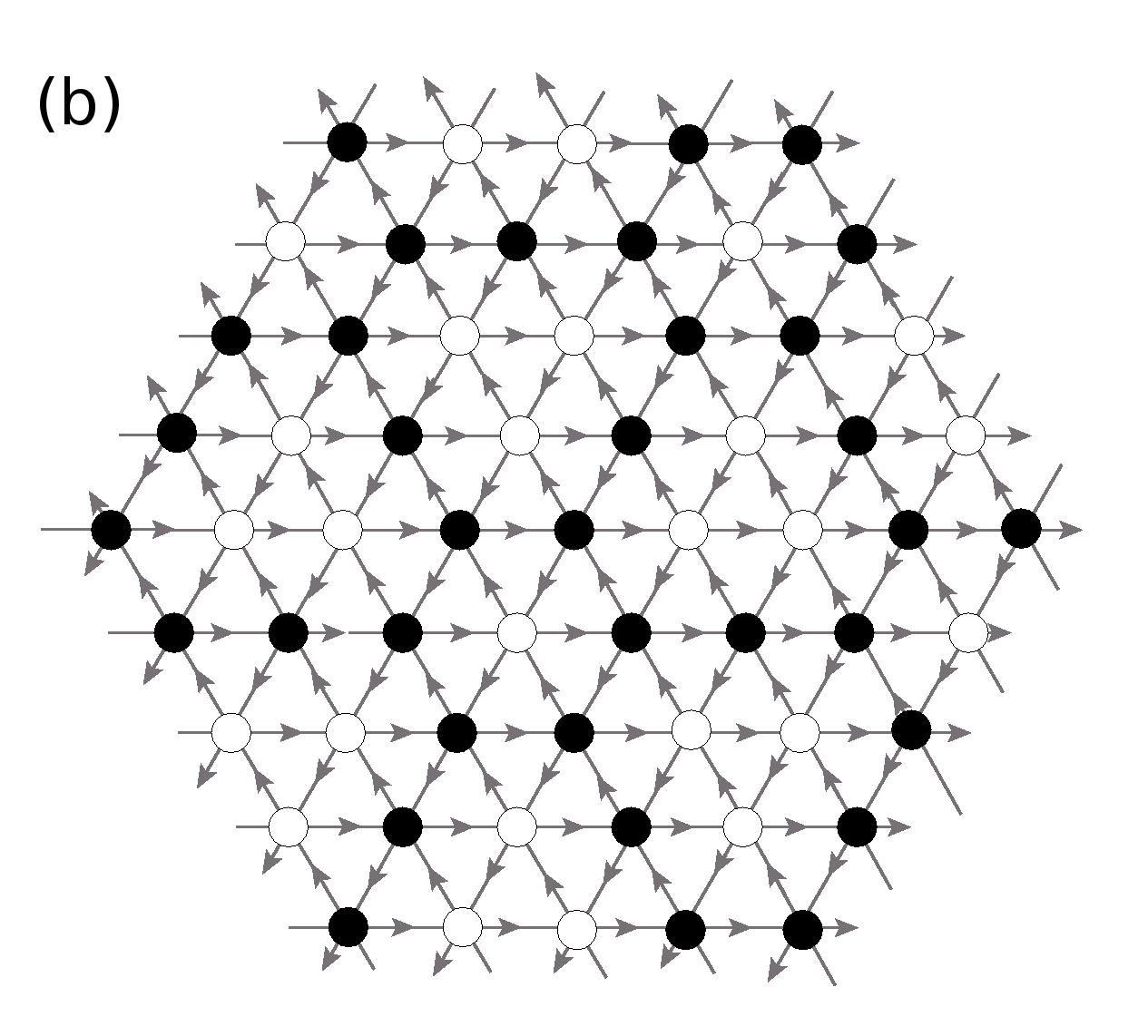
There are some earlier work on the growth rate of the sandpile patterns. Some backgrounds of both types, explosive and non-explosive, for a deterministic ASM were studied in [explosion, fey]. In all the examples, studied so far, the background is either explosive or the growth of the patterns is compact. For a deterministic ASM on a square lattice, it was shown [fey], that the pattern produced on a background of constant height , is always enclosed inside a square whose width grows as . Given the absence of any critical density, it is non-trivial to find a background on which the patterns grow with a rate faster than , but finite. In fact, for the sandpile models on a standard square lattice there are no known examples of patterns with non-compact growth.
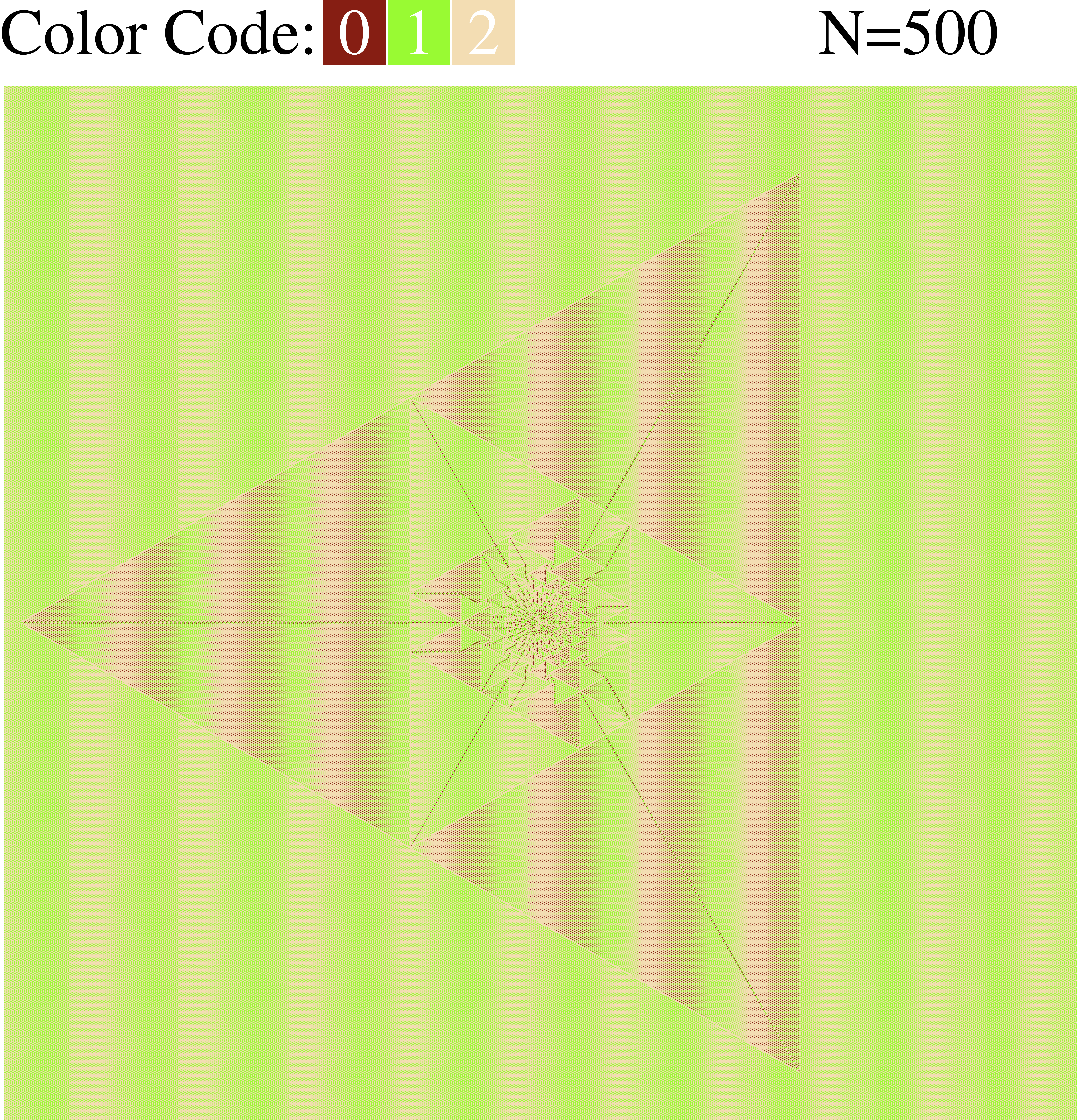
We found two classes of backgrounds, both infinite, on a directed triangular lattice (see Fig. 6.1), for which the growth is proportionate, with the growth exponent . Examples of these classes of backgrounds and patterns formed on them are shown in Fig. 6.2, Fig. 6.3 and Fig. 6.4. Our numerical study shows, but we have no formal proof, that different backgrounds belonging to the same class produce the same asymptotic pattern. In addition, we found infinitely many backgrounds on the F-lattice which produce patterns with proportionate non-compact growth. However, in these cases the growth exponent takes a different value, with for each member.
We also discuss the exact characterization of the pattern shown in Fig. 6.3, one of the two asymptotic patterns we have found with . This is described, as in the earlier studied case of compact growth (see previous chapters), in terms of the scaled toppling function. However, the analysis of non-compact patterns is actually simpler. Clearly, for , the mean excess density of particles in the toppled region is zero, in the asymptotic patterns. Infact, the patterns are made of large patches where heights are periodic, and inside each patch, the mean density is exactly the same as in the background, and the excess grains are concentrated along the patch boundaries. There are also some boundaries where excess grains density is negative. We show that this leads to the scaled toppling function being a piece-wise linear function of the rescaled coordinates. Thus, in each patch, the potential function is specified by only three coefficients. In contrast, for the compact patterns discussed in chapters 4 and 5, the scaled toppling function is a quadratic function of the coordinates in each patch, and one has to determine six coefficients for each patch, to determine the function fully.
We are able to reduce the problem of determining the asymptotic pattern in Fig. 6.3 to that of finding the lattice Green’s function on a hexagonal lattice. This is known to be expressible as integrals that can be evaluated in closed form (see Appendix A), and this leads to a full solution of the problem. This is in contrast to the characterization of the compact growth patterns in previous chapters, where one requires solution of Discrete Laplace’s equation on a square grid on Riemann surfaces of multiple sheets, and there are no known closed form expression for the solution.
This chapter is organized as follows: In section 6.2, we discuss, in details, how different periodic background configurations give rise to different rates of growth. In section 6.3 we define a deterministic ASM on the directed triangular lattice, and describe the two classes of periodic backgrounds that produces patterns with non-compact growth. In section 6.4 we argue that, for any pattern with non-compact proportionate growth the rescaled toppling function is piece-wise linear. In section 6.5, we discuss exact characterization of the simplest of the non-compact growth patterns with . Patterns on the F-lattice, with are discussed in section 6.6. The section 6.7 contains some discussion about connection to tropical polynomials.
6.2 Compact and non-compact growth
The simplest growing patterns are found in the Manna-type sandpile models with stochastic toppling rules [sasm]. In these models, when the density of particles in the background is small, the avalanches are always finite. In the relaxed configuration, the toppled sites form a nearly circular region (see Fig. 6.5). The asymptotic pattern seems to be perfectly circular disc of uniform density, with an average density inside the circle and outside. The value of is independent of the background density , and is equal to the unique steady state density of the corresponding self organized critical model with random sites of addition, and dissipation at the boundary [sasm]. The region inside the circle forgets about the initial height configuration, and is in the self-organized critical state. The boundary of the affected region is thin with a sharp transition of density from to (see Fig. 6.6). Then considering that, for large , all the added grains are confined inside the circular region of diameter , we get
| (6.1) |
Thus the pattern has a compact growth.
For densities close to, but below , sometimes a single particle addition can lead to very large increase in the size of the toppled region. However, probability of such large jumps decreases exponentially with size, and for any finite , with probability , avalanches remain finite. As long as is less than , the system relaxes, forming a pattern whose diameter grows as . Adding a single grain on a background of super-critical density () gives rise to infinite avalanches, with non-zero probability. Then, with probability , such backgrounds will lead to an infinite avalanche for some finite value of . In higher dimensions also, a similar behavior is expected.
At the probability of large avalanches has a power law tail, and the above argument does not apply. It may be possible to construct a robust background with critical density of heights. However, no such example has been found, so far.
In the models with deterministic relaxation rules there is no well defined critical density , separating the explosive and non-explosive backgrounds. The geometry of height distribution plays the determining role in the robustness of a background.
In the deterministic models, similar circular pattern is produced for a background with random assignment of heights per site, of small average density . Inside the pattern, density of heights is which is the steady state density of the corresponding SOC model. However, on a background of higher densities, this picture is changed considerably. For example consider the BTW model on a square lattice, where the steady state density . It has been shown that a background with a random assignment of height with probability , on a sea of constant height is explosive, even for arbitrary small value of [explosion], although the average density is much less than .
For a background with periodic heights, it is possible to construct explosive backgrounds of any density, even with arbitrary small values. As an example, we consider the BTW model on an infinite square lattice. Define a background made of square unit cells of width with empty sites inside the cell, and grains at each site in the boundary. For , the average density . If any of the occupied site receives a grain, it starts a chain of toppling events where all the occupied sites topple, and the avalanche reaches infinity.
On the other hand a constant background of height at all sites is a minimally stable configuration i.e, addition of a single grain will produce an infinite avalanche. Still, it is possible to construct a robust background with density arbitrarily close to . For example, consider the background in the previous example, and exchange the height variables: make the occupied sites empty, and fill the empty sites with grains. It has been shown [explosion], that this background is stable and the pattern produced has a compact growth.
We will show in the next section that, there is a large class of backgrounds, with a range of densities, for which the growth is less than explosive, but more than compact.
6.3 Examples of non-compact growth
We first discuss the patterns with . We start with an ASM on a directed graph corresponding to an infinite two dimensional triangular lattice, with each site having three incoming and three outgoing arrows (see Fig. 6.1). The threshold height , for each site. If the height at any site is above or equal to , it is unstable, and relaxes by toppling: in each toppling, three sand grains leave the unstable site, and are transferred one each along the directed bonds going out of the site.
We consider two classes of backgrounds on this lattice:
-
Class : We consider the lattice as made of triangular plaquettes, which are joined together to make tiles in the shape of regular hexagons with edges of length . We cover the two-dimensional plane with these tiles. Sites that lie on the boundaries of these hexagons are assigned height , and the rest of the sites have height . Figure 6.2 shows the background configuration for the case .
-
Class : For these backgrounds, we cover the two-dimensional plane with tiles in the shape of equilateral triangles of edge-length . The sites that lie on the boundaries of the triangles, and are shared by two triangles, are assigned height , and remaining sites are assigned height . Sites that are at the corners of triangular tiles, and shared by six of them, are also assigned heights . The background configuration corresponding to is shown in figure 6.2. The pattern made of triangular tiles with is same as the class I background with hexagon of edge-length . Hence, only patterns formed with triangles of edge-length will be said to be in this class.
The patterns produced by adding grains, where is large, at a single site on the two backgrounds in Fig. 6.2 are shown in Fig. 6.3 and 6.4. While the patterns look quite similar, a closer examination shows that they are not identical. In Fig. 6.4, there are extra lines of particles within the brownish patches which break each patch into smaller parts. In fact, with the identification of some patches having only a point in common, as discussed later, we can show that each patch breaks into exactly three patches. These three parts have similar periodic pattern, but with different orientations.
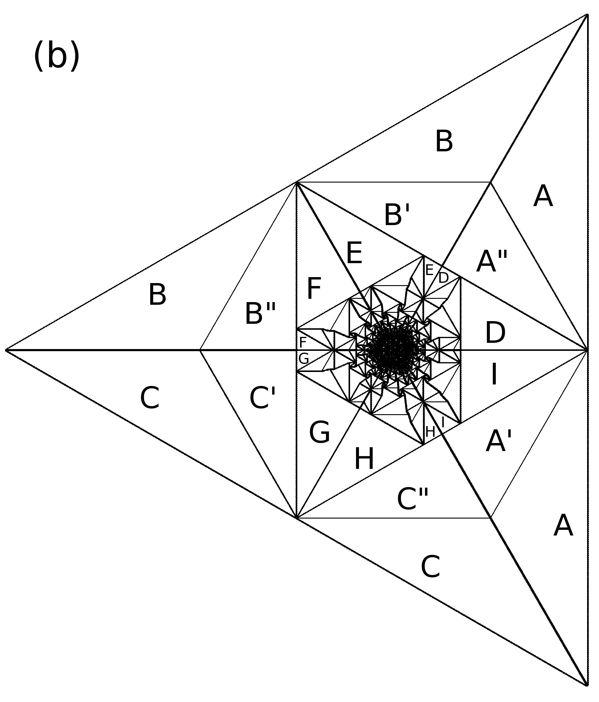
This differences can be seen more clearly in terms of the net excess change in height in a unit cell centered at , where the unit cell is that of the background pattern.
| (6.2) |
where is the change in height at site . For example in the first background in Fig. 6.2 a unit cell is a hexagon of edge length , and for the second background it is a parallelogram of each side length . A site that is on the edge of the unit cell is counted with weight , and a site on the corner of the hexagon with weight , and on the corner of the parallelogram with weight . By construction, the function is zero inside each patch, and non-zero along the boundaries between patches. The patterns in terms of these variables, corresponding to those in Fig. 6.3 and 6.4 are shown in Fig. 6.7.
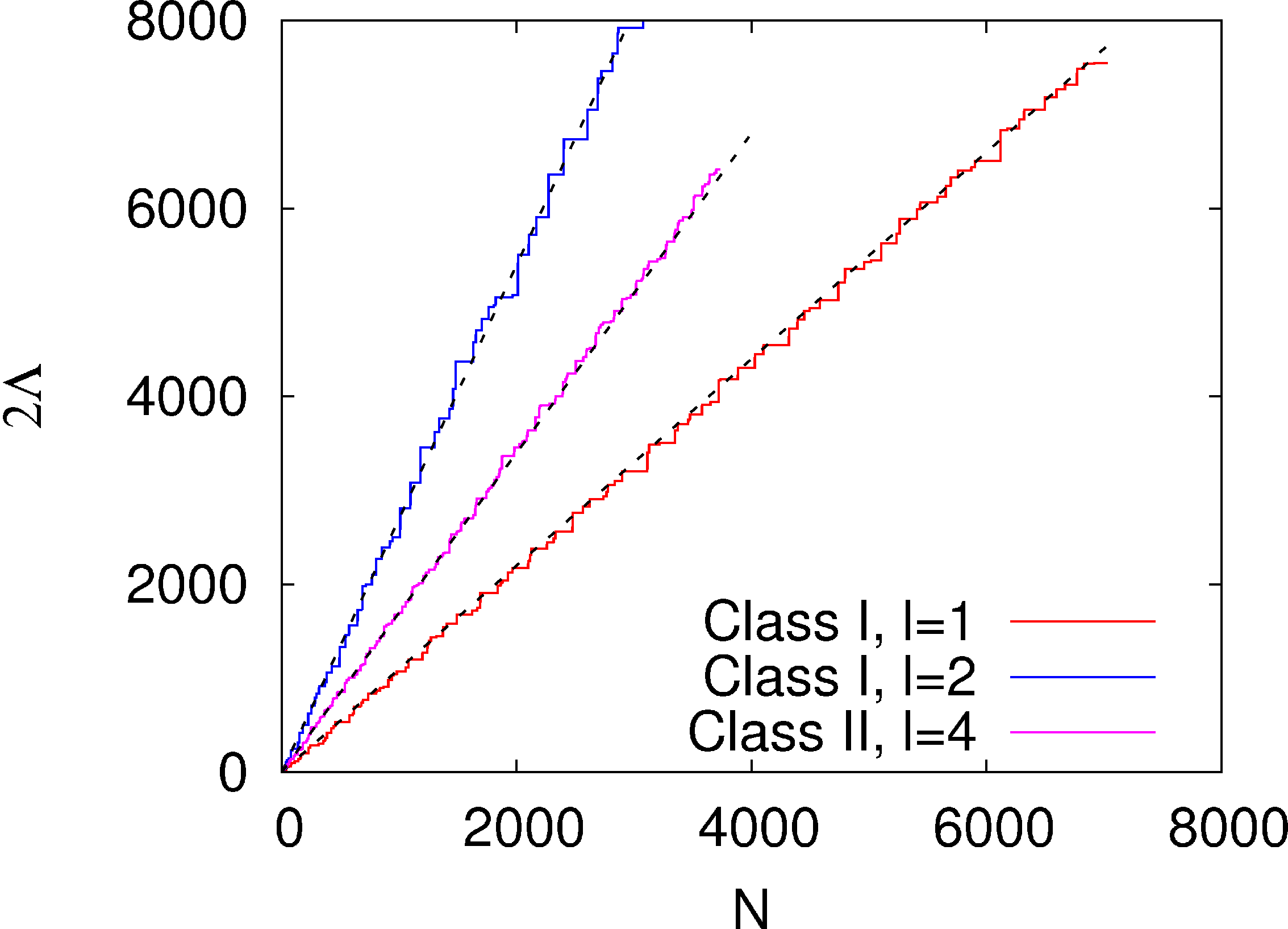
We have seen that the patterns on these two classes of backgrounds exhibit proportionate growth, i.e., all the spatial features inside the patterns for large , grow at the same rate with the diameter. We define the diameter , in general, for any pattern in this paper, as the height of the smallest rectangle containing it. For the patterns in Fig. 6.3 and Fig. 6.4, it is then the length of a side of the bounding equilateral triangle. This particular choice makes as an integer multiple of , on the triangular lattice. We find that for both types of backgrounds in Fig. 6.2, the diameter of the pattern grows linearly with (Fig. 6.8).
6.4 Piece-wise linearity of the toppling function
Considering the proportionate growth, let us define a rescaled coordinate , where is the position vector of a site on the lattice. The number of topplings at any site inside the pattern, scales linearly with . Let us define
| (6.3) |
We now show, using an extension of the argument given in chapter 4, that the function is linear inside periodic patches in all the patterns with non-compact growth, i.e., with . Within a patch, the function is expandable in Taylor series around any point , not on the boundary of the patch. Defining , and we have
| (6.4) |
Consider any term of order in the expansion, for example, the term . This can only arise due to a term in the toppling function . Then, considering the fact that is an integer function of and , it is easy to see that this term would lead to discontinuous changes in at intervals of . As for non-compact growth patterns, this leads to a change in the periodicity of heights at such intervals inside each patch which themselves are of size . This would then result in many defect lines within a patch, in the pattern at large . However there are no such features in Fig. 6.10. Therefore inside each periodic patch, must be exactly linear in . In fact, it turns out that the integer toppling function is exactly linear inside a patch even for any finite , except for an additional periodic term of periodicity equal to that of the heights inside the patch.
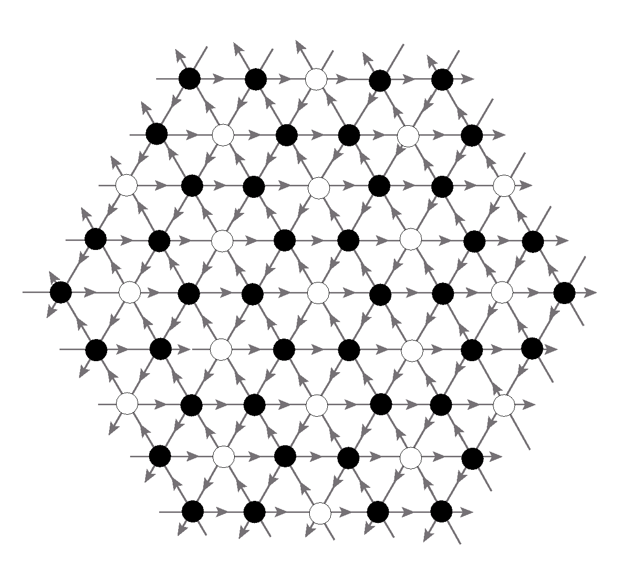
Another consequence of the exact linearity of the potential function in each patch is that all patch boundaries in the asymptotic pattern are straight lines.
The argument finally relies on the two observed (not rigorously established) features of the patterns, i.e., there is proportionate growth, and that the patterns can be decomposed in terms of periodic patches which are themselves of size .
Let us write the toppling function within a single patch as
| (6.5) |
where is a periodic function of its argument with zero mean value. If and are the basis vectors at the unit cell of the periodic pattern then we have
| (6.6) |
As are integer valued functions, and can only take integer values. If and are the unit vectors in the reciprocal space of the super lattice of the periodic pattern,
| (6.7) |
then must be an integer linear combination of and , and can be written as
| (6.8) |
where and are some integers. For example, in the background pattern in Fig. 6.9, a choice of the basis vectors and its reciprocal vectors is
| (6.9) |
The fact that is constant inside a patch, implies that the patches can be labeled by the pair of integers .
An interesting consequence of this linear dependence of is that there are no transient structures within the patches. On increasing , if the function increases, all sites in the patch , except possibly those at the patch boundaries, undergo same number of additional topplings.
6.5 Characterizing the class asymptotic patterns
We now discuss characterization of the asymptotic pattern of class I, showing . In this section we quantitatively characterize the asymptotic pattern for the case . The background configuration is shown in Fig. 6.9. A site on the triangular lattice can be labeled uniquely by a pair of integers , such that its position on a complex plane can be written as , where is a complex cube root of unity. Then, the height variables in the background pattern in Fig. 6.9, can be written as
| (6.10) | |||||
The average height in the background, . The configuration of the pile produced on this background, by adding grains at the origin is shown in Fig. 6.10.
We see that the sites toppled due to addition of the grains are confined within an equilateral triangle. The pattern can be thought of as a union of patches, inside which the heights are periodic. A zoom-in showing the height configuration with five patches meeting at a point is shown in Fig. 6.11. There are only two types of periodic patches seen: one is like the background, where the sites of height are surrounded by sites of height , and the other with heights surrounded by heights . Then, the average height inside both types of patches are same. In fact, it is equal to that of the background, .
The patches in the outer region of the pattern are big, and they become smaller, and more numerous as we go inwards. Along the common boundary of adjacent patches, we see line-like defect structures, and only along these lines the density is different from the background. In Fig. 6.11, one can also see the periodicity of the structures along the patch boundaries. Some patch boundaries, like the horizontal boundary in Fig. 6.11, have a deficit of particles compared to the background.
The boundaries of the patches are seen more clearly in terms of variables, as shown in figure 6.7(a), where we have labelled different patches as etc..
.
The dependence of on for this background is shown in Fig. 6.8. We see that the diameter for the pattern grows asymptotically linearly with , but it grows in bursts: it remains constant for a long interval as more and more grains are added, and suddenly increases by a large amount at certain values of . For example, at , the is , and it jumps to a value when one more grain is added. Let denote the size of the maximum jump in encountered, as is varied from to . In Fig. 6.12, we have plotted the variation of with . The graph is consistent with a power-law growth, with a power around . Thus the fractional size of the bursts decreases for large .
We define scaled complex coordinates , where is the complex coordinate of the site . We define the rescaled toppling function for this pattern as
| (6.11) |
Then it is easy to see that is equal to the mean flux of particles at . If we consider a small line element , then the net flux of particles across the line equals . Then, the conservation of sand grains implies that the toppling function satisfies the equation
| (6.12) |
where is the finite-difference operator on the lattice, corresponding to the Laplacian . It is easy to see that this implies that the scaled potential function satisfies the Poisson equation
| (6.13) |
where is the areal density of excess grains at . It is related to , the mean excess grain density per site by
| (6.14) |
The piece-wise linearity of simplifies the analysis of the pattern, significantly. The potential function can be characterized by only three parameters. Using Eq. (6.8), (6.9) and (6.11), for each patch , we can find a pair of integers such that the potential in patch is characterized by
| (6.15) |
where
| (6.16) |
and is a real number, constant everywhere inside the patch. Here denotes the complex conjugate of .
Each patch is characterized by a complex number which is the coefficient in the potential function of the patch. In the complex -plane, each patch with labels as in Fig. 6.7(a) can then be represented by a point. We connect two patches by a line if they share a common boundary. Then the resulting figure, shown in Fig. 6.13, is the adjacency graph of the patches.
We can determine the connectivity structure of this graph, without knowing the full potential function in each patch. We first take transformation of the pattern. This is shown in Fig. 6.14. Some of the bigger patches are denoted by capital alphabets in Fig. 6.7(a) and their corresponding patches on the transformed pattern in Fig. 6.14. The patches A and in Fig. 6.7(a) are adjacent to the outer region O through the same vertical boundary. Matching the values of the function and fixing the discontinuity in its normal derivatives at the boundary, it is easy to see that has the same functional form in the patches A and . In fact, it is convenient to imagine that the boundary between O and A moved to the right by an infinitesimal amount, so that it does not touch the patches D and , and then A and would actually join to form a single connected patch A. We thus consider A and as one patch, and both can be represented as one point on the -plane. Similarly, we identify B and , C and , etc. Then the adjacency graph can be constructed by joining the sites on the -plane, according to the adjacency of patches in Fig. 6.14.
It turns out that the patches corresponding to mod do not appear in the pattern, and the adjacency graph, as shown in Fig. 6.13, is a hexagonal lattice with some extra edges shown in brown color. These extra edges connect all the vertices at same distance from the origin (in the metric), and also connect some of the diagonally opposite sites on the rectangular faces of the graph as shown in figure.
The charge density is zero inside the patches, and the excess grains due to addition are distributed along the patch boundaries, leading to nonzero line charge densities separating neighboring patches. Then the density function is a superposition of the line charge densities along the patch boundaries. There are three kinds of line charges of charge density , , and .
From the electrostatic analogy, it is seen that is continuous across the common boundary between neighboring patches, and its normal derivative is discontinuous by an amount equal to the line charge density along the boundary. Let and be the two neighboring patches with the equation of the boundary between them
| (6.17) |
such that the patch is on the left of the boundary. Then using the continuity condition, it is easy to show that
| (6.18) |
where is the complex conjugate of . We note that, there are only six different types of patch boundaries in the pattern, with angle an integer multiple of .
It is easy to check that the matching conditions along the edges of hexagonal lattice (denoted by blue solid line in Fig. 6.13) are sufficient to determine for all the vertices. The line charge density for the patch boundaries corresponding to these edges. Also, the potential function , for the vertex at the origin, and hence, and both vanishes. Then using the matching condition, it is easy to check that, the values of are consistent with the form in Eq. (6.16).
The function satisfies the discrete Laplace’s equation on the underlying hexagonal lattice of the adjacency graph i.e.
| (6.19) |
where denotes the three neighbors of the vertex on the hexagonal lattice. This can be checked from the concurrency condition of patch boundaries. For example consider the edges , and on the adjacency graph. The corresponding patch boundaries in the pattern intersect at the same point (Fig. 6.7(a)). Then it is easy to check using the matching condition in Eq.(6.18) that,
| (6.20) |
Similar equations hold for the other vertices.
In the region outside the pattern, where none of the sites toppled, the potential function . This corresponds to , and . The solution of the Laplace’s equation with the above boundary condition can be written in the following integral form [atkinson]
| (6.21) |
for (mod ), where is a normalizing constant, which determines the pattern up to a scale factor. For the sites with (mod ), are the average of those corresponding to the neighboring sites. As an example the potential function in region A, and is
| (6.22) | |||||
| (6.23) |
where , and . Then the equation of the patch boundary between patches A and O is
| (6.24) |
and that of the boundary between patches and O is
| (6.25) |
Equivalently, the length of an edge of the bounding equilateral triangle of the pattern is equal to , for large .
The constant in Eq. (6.21) can be calculated using the form of the potential function near the site of addition. As noted, the function can be considered as the potential due to line charges along the patch boundaries and a point charge of unit amount at the origin. Then, close to the origin the solution diverges logarithmically as , and the potential function is an approximation to this solution by a piece-wise linear function. Then, there are coordinates inside each patch with large, where the and its first derivatives are equal to and its first derivatives, respectively. Then,
The above two equations imply
| (6.27) |
for large. Comparing it with the Eq. (6.21) for large we find that the numerical constant . This determines the potential function completely, and thus characterizes the pattern. For example, as in figure 6.7(a), the equation of the rightmost boundary of the pattern, using Eq. (6.24) is . Equations of other boundaries of patches can be calculated similarly. For example, the reduced coordinates of the point where the patches and meet in Fig. 6.7(a), is determined by the condition that it is a common point of patches , and , and that the function is continuous.
| (6.28) | |||||
Then using the values , , and [atkinson] we get the reduced coordinates of this point as
| (6.29) |
Equivalently, the height of the bounding equilateral triangle increases as . The estimated slope of the fitting line in Fig. 6.8 is 1.1, in reasonable agreement with the theory. However, even though the exact function has large fluctuations of number theoretic origin, the estimated slope is noticeably lower than the calculated asymptotic value. To examine this discrepancy closer, we have plotted in Fig. 6.15 the discrepancy as a function of . We find that this appears to increase with as , for large . The reason for this behavior is not understood yet.
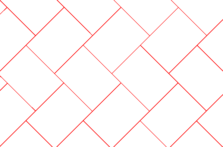
For backgrounds, with , our numerical results suggest that there is a crossover length , and initially, for , the avalanches grow “explosively" in size. As a result, the number of particles inside a disc of radius in the final pattern is less than that in the initial background. The net flux of particles going out of the disc increases with until the radius becomes of order . After this, the large-scale properties of the pattern are the same as that of pattern, with the number of particles added , where is an -dependent constant. In particular, the size of the pattern is -times the size of the pattern for with same . The crossover length is expected to grows as .
For a background with , the basis vectors at the unit cell are and , where , are the basis vectors for background (see Eq. (6.9)). Then the reciprocal basis vectors are and . From the observed patterns, we find that the line charge densities remain same for any (see Fig. 6.16 for an example of the patch boundaries). This implies that and in eq. (8) are constrained to be multiples of . Writing , , we see that the patches can be labeled by the same pair of integers as in the case, and the potential function for general is related to the case by simple scaling:
| (6.30) |
where is a scale factor. For , , and the values of are approximately , , and , respectively. We note that increases approximately linearly with .
6.6 Non-compact patterns with exponent .
On the F-lattice, after some experimentation, we found that the background pattern having the periodicity of the tiling of plane with tilted rectangles, shown in Fig. 6.17, produces patterns with interesting non-compact growth. We studied rectangles with aspect ratio , and the rectangles are tilted by to the x-axis. Two such periodic backgrounds are shown in Fig. 6.18. In these background patterns, the sites with height zero, are arranged along the boundaries of tilted rectangles with two possible orientations, and rest of the sites have height one. The stable height-patterns generated by adding particles and relaxing the configuration on these two backgrounds are shown in Fig. 6.19 and Fig. 6.20, respectively. The growing boundaries of the patches in the patterns are shown, in terms of the variables, in Fig. 6.21 and 6.22, respectively. Again, we see that the patch boundaries are straight lines, with rational slopes. The plot of diameter vs N, for these two patterns are shown in Fig. 6.23. We see that the growth exponent is approximately for figure 6.19 and for figure 6.20. In general, value of the exponent is in range , and approaches value as density of the background becomes close to .
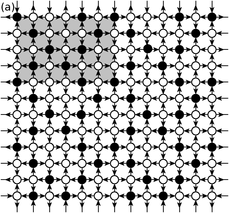
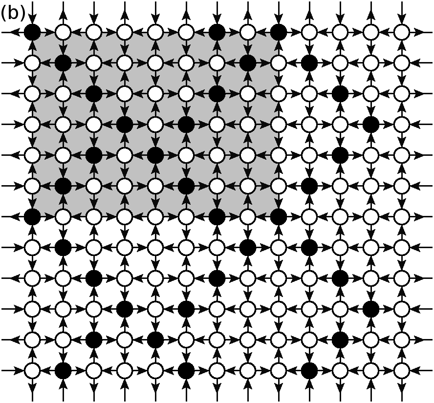
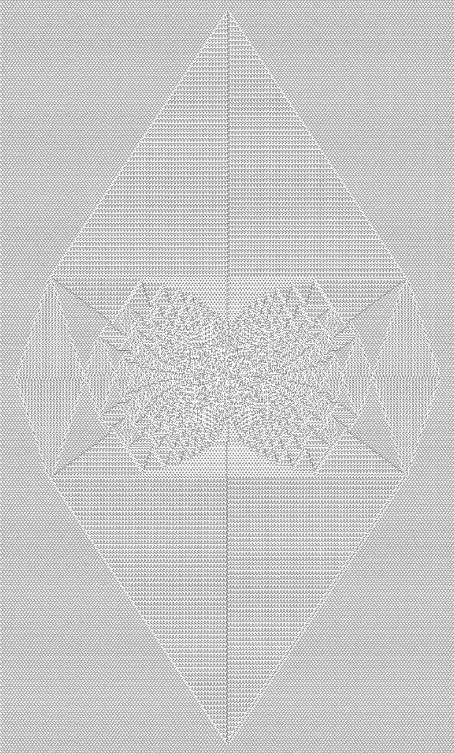
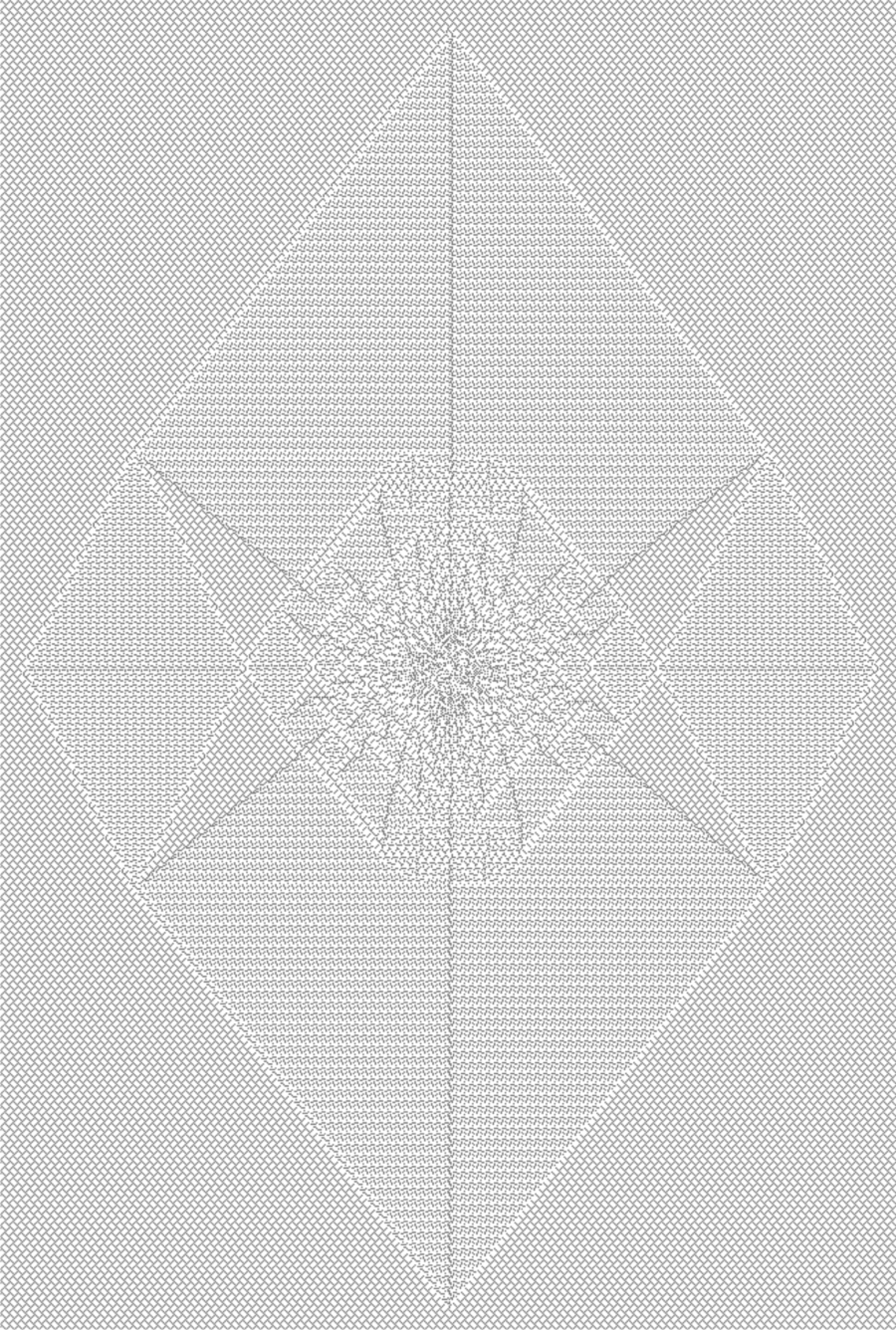
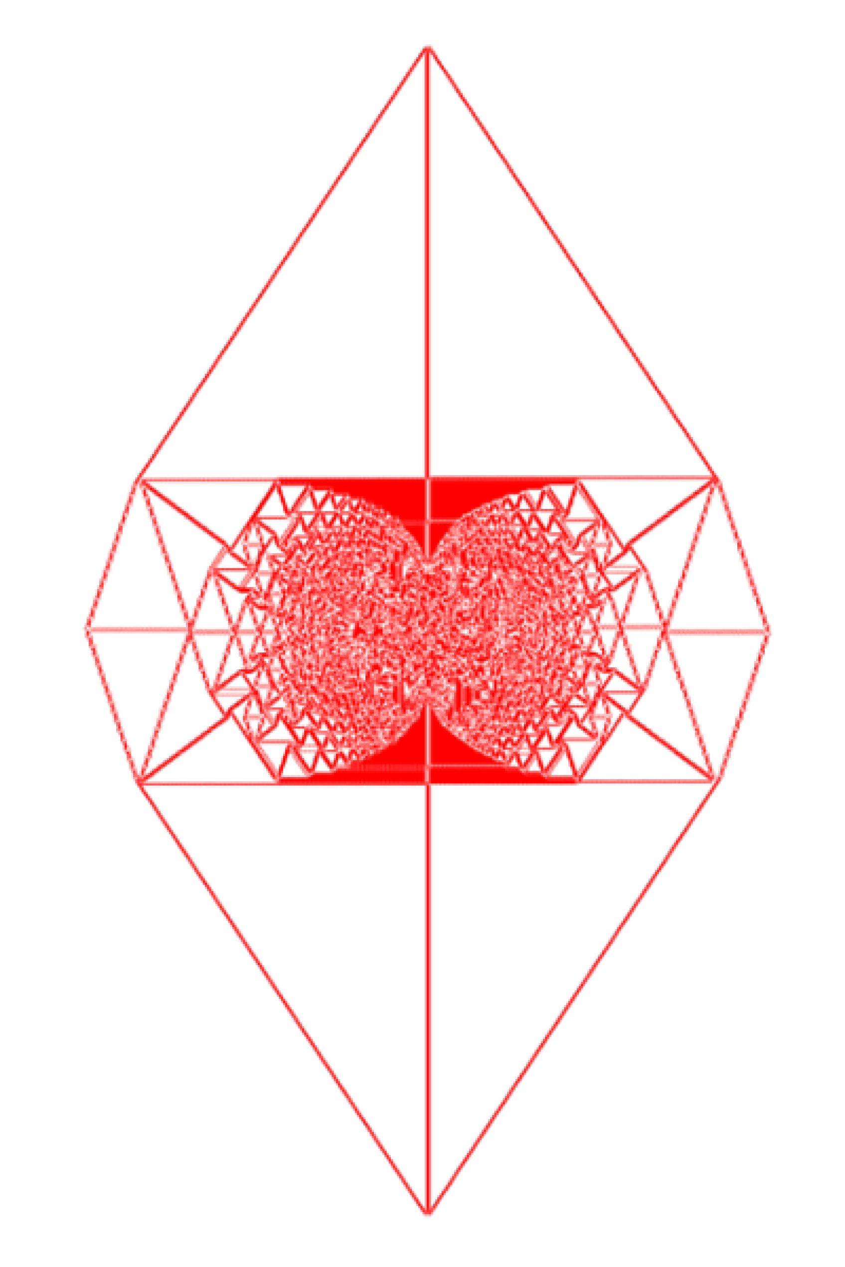
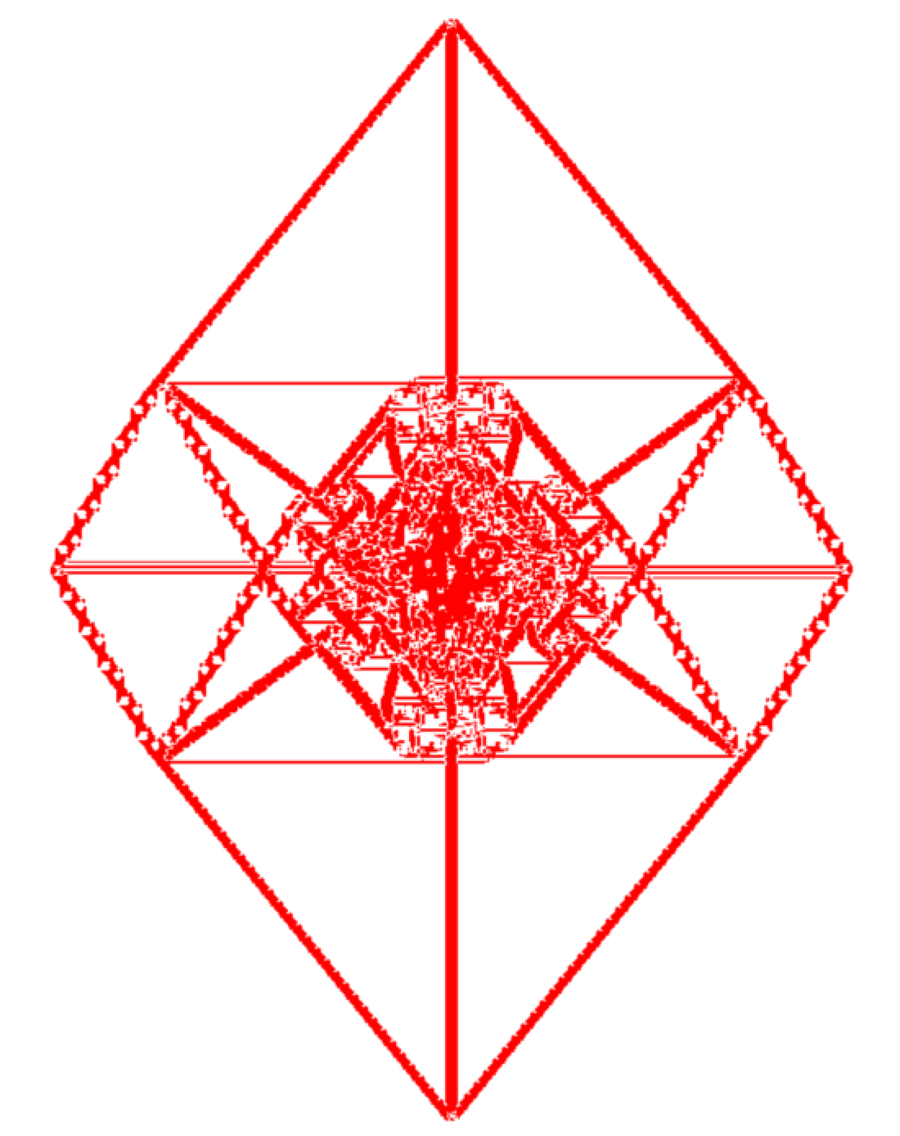
There are unresolved areas of apparent solid color in the patterns, taking up a sizable fraction of the total area, e.g., two large regions of red color on both sides of Fig. 6.21. In these regions, the pattern appears to be complex, suggesting either a large number of patch boundaries, or patches of non-zero areal excess charge density. However, the fractional area of these regions decreases with larger . Also on comparing patterns with different , we have seen that the fractional area of such regions decreases as increases. A more detailed study of these patterns seems like an interesting problem for future investigations.
6.7 Summary and concluding remarks
In this chapter, we have studied two dimensional patterns formed in Abelian sandpile models by adding particles at one site on an initial periodic background, where the diameter of the pattern grows as , with . Using some features observed in the pattern of adjacency of patches as an input, we are able to determine the exact asymptotic pattern in the specific case with , on a class background.
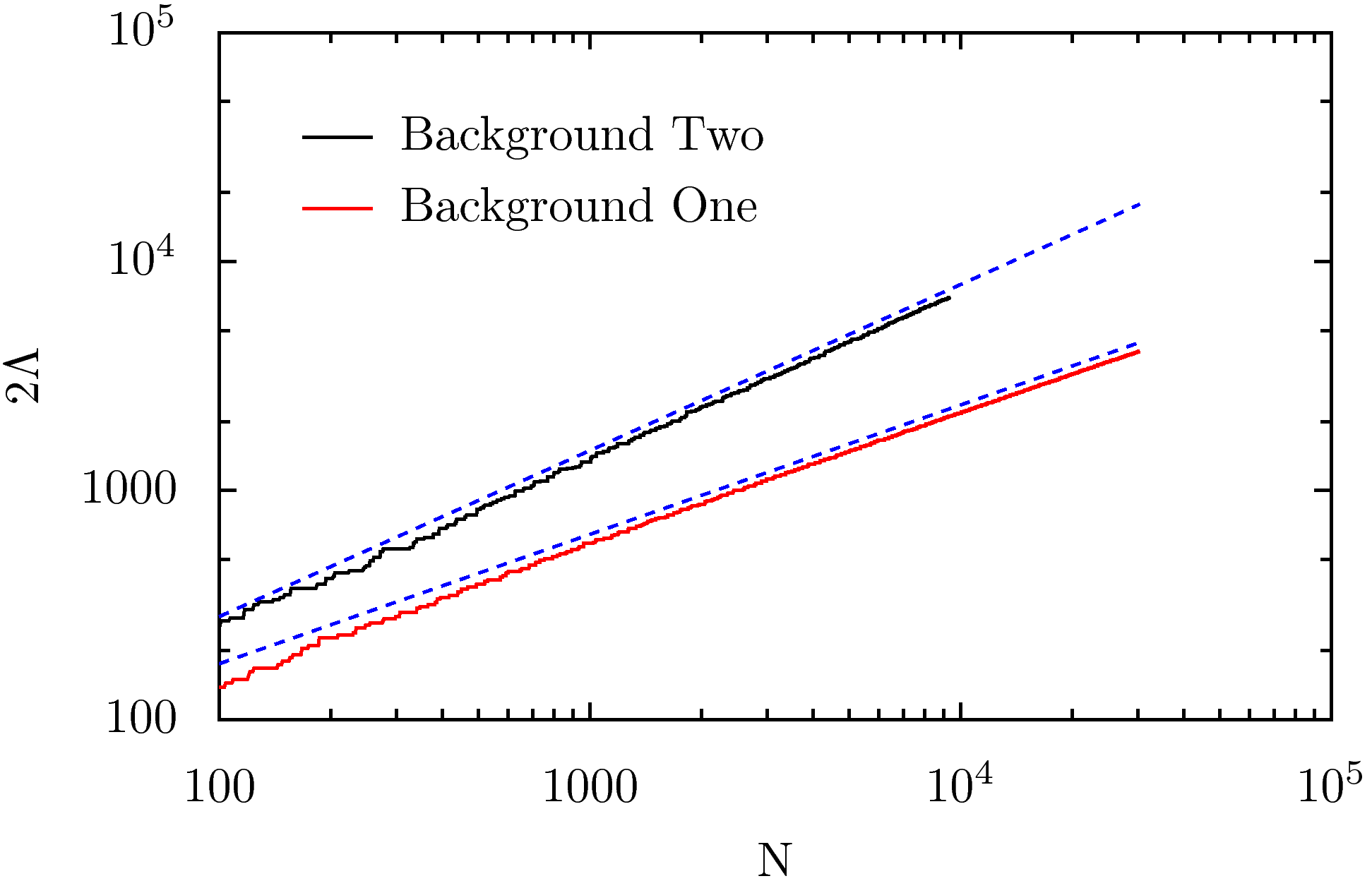
The patterns on class backgrounds can also be characterized similarly. As noted earlier, some of the patches split into smaller parts. By using the transformation, we can again determine the structure of the adjacency graph. The graph for the pattern in Fig. 6.7(b) is shown in Fig. 6.24. It is a periodic lattice where half of the vertices of the hexagonal lattice are replaced by vertices (colored in brown). The exact D-values for different patches can be easily determined. The determination of for this pattern then requires the solution of the Laplace’s equation on this graph. It can be shown that a slight alteration of the graph, by drawing the missing edges in the small triangles shown in pink colors, does not change the pattern. Then the solution of the Laplace’s equation can be reduced to the solution of a resistor network on this modified graph. The later can be further reduced to the resistor network on a hexagonal lattice, discussed by Atkinson et.al. [atkinson], using the well-known transformation. We present the analysis in the Appendix LABEL:apndx:laplace.
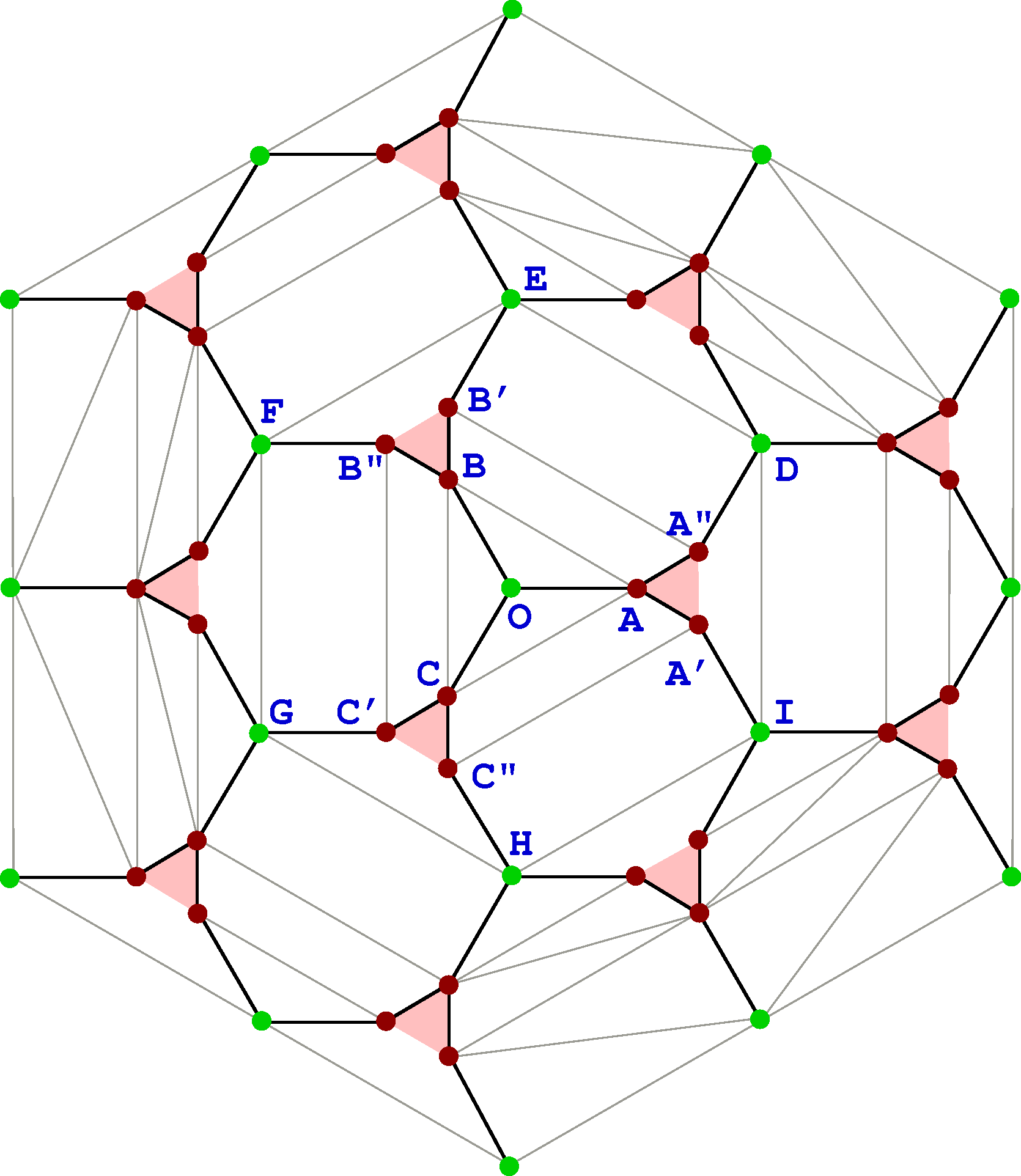
An important feature of the non-compact patterns is that, it can be characterized by a piece-wise linear function. This characterization is simpler than that of the patterns with compact growth, where one requires piece-wise quadratic polynomials. We have shown that there are infinitely many backgrounds, on which the patterns have non-compact growth. It would be desirable to determine the exact value of for different backgrounds showing non-compact growth studied in section 6.6.
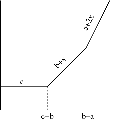
Another interesting question is a possible connection of this problem to tropical algebra [tropical]. In tropical mathematics, one defines operations similar to ‘addition’ and ‘multiplication’ (denoted by and here) by
| (6.31) |
where , are real parameters. Familiar properties of addition and multiplication operators, like commutativity, associativity, existence of identity, distributive property continues to hold in the new definition. One can then define polynomials in several variables. The graph of a tropical polynomial is a piecewise linear function which is also convex. For example, consider the tropical function
| (6.32) |
In terms of standard algebra
| (6.33) |
The graph corresponding to this function is shown in Fig. 6.25
We note that for the pattern discussed in section , the potential function is piece-wise linear. It seems plausible that tropical polynomials may be useful to describe this function. In fact, tropical geometry have been discussed as possibly related to sandpile models [norine, propp2]. For small values of , our numerical study showed that is convex, if restricted to one sextant. However, for larger , as shown in Fig. 6.26, we see that is not convex even within one sextant.
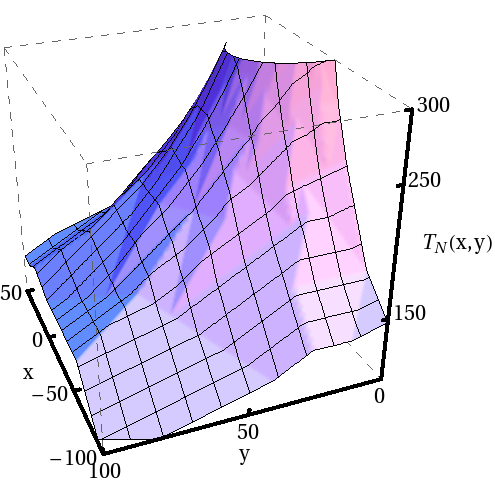
We conclude that it is not possible to represent the potential as a simple tropical polynomial.
Chapter 7 A continuous height sandpile model
Based on the paper [mypre] by Tridib Sadhu and Deepak Dhar.
-
Abstract:
In this chapter, we study the Zhang model of sandpile, defined in the first chapter, on a one dimensional chain of length , driven by adding a random amount of height at a randomly chosen site at each addition step. We show that in spite of this randomness in the input height, the probability distribution function of height at a site in the steady state is sharply peaked, and the width of the peak decreases as for large .
We also discuss how the height added at one time is distributed among different sites by topplings with time. We relate this distribution to the time-dependent probability distribution of the position of a marked grain in the one dimensional abelian model with discrete heights. We argue that in the large limit, the variance of height at site has a scaling form , where varies as for small , which agrees well with the results from numerical simulations.
7.1 Introduction
After Dhar first discovered the abelian property of the BTW model [dharprl], many more models in the general class known as abelian distributed processors, were studied, as the abelian property makes their theoretical study simpler [dharphysica06]. The original sandpile model of Bak et al. [btw], the Eulerian walkers model [euler], and the abelian variant [sasm] of the model originally proposed by Manna [manna] are all members of this class. Models which do not have the abelian property have been studied mostly by numerical simulations. As discussed in chapter 3, the Zhang model is one such model, and this is what we study in this chapter.
In the Zhang model, the amount of height added at a randomly chosen site at each addition step is not fixed, but random. In spite of this, the model in one dimension has the remarkable property that the height at a site in the steady state has a very sharply peaked distribution in which the width of the peak is much less than the spread in the input amount per time step, and the width decreases with increasing system size . This behavior was noticed by Zhang using numerical simulations in one and two dimension [zhang], and he called it the ‘emergence of quasi-units’ in the steady state of the model. He argued that for large systems, the behavior would be same as in the discrete model. Recently, A. Fey et al. [redig] have proved that for some choices of the distribution of input height, in one dimension, the variance of height does go to zero as the length of the chain goes to infinity. However, they did not study how fast the variance decreases with .
We study this emergence of ‘quasi-units’ in one dimensional Zhang sandpile by looking at how the added height is redistributed among different sites in the avalanche process. We show that the distribution function of the fraction of height, added at a site , reaching a site after time steps following the addition is exactly equal to the probability distribution that a marked grain in the one-dimensional height type BTW model added at site , reaches site in time . The latter problem was studied earlier [punya]. We use this to show that the variance of height asymptotically vanishes as . We also discuss the spatial dependence of the variance along the system length. In the large limit, the variance at site has a scaling form . We determine an approximate form of the scaling function , which agrees very well with the results of our numerical simulations.
There have been other studies of the Zhang model earlier. Blanchard et al. [blanchard] have studied the steady state of the model where the amount of addition of height is fixed but the site of addition is chosen randomly, and found that the distribution of energies even for the two site problem is very complicated, and has a multi-fractal character. In two dimensions, the distribution of height seems to sharpen for larger , but the rate of decrease of the width is very slow [janosi]. Most other studies have dealt with the question as to whether the critical exponents of the avalanche distribution in this model are the same as in the discrete abelian model [lubeck, milshtein]. A. Fey et al.’s results imply that the asymptotic behavior of the avalanche distribution in one dimension, for specific cases, is identical to the discrete case, but the situation in higher dimension remains unclear [vespignaniz, guilera].
The plan of the chapter is as follows. In Section 7.2, we define the model precisely. In Section 7.3, we show that the way the height added at a site is distributed among different sites by toppling is same as the time-dependent probability distribution of the position of a marked grain in the discrete abelian sandpile model. This correspondence is used in Section 7.4 to determine the qualitative dependence of the variance of the height variable at a site on its position , and on the system size . We propose a simple extrapolation form that incorporates this dependence. We check our theoretical arguments with numerical simulations in Section 7.5. Section 7.6 contains a summary and concluding remarks. A detailed calculation of the solution of an equation, required in Section 7.4, is given in the Appendix C.
7.2 Definition and preliminaries
We consider our model on a linear chain of size . The sites are labelled by integers to and a real continuous height variable is assigned to each site. Let be the height variable at site at the end of the time-step . We define a threshold height value , same for each site, and sites with are called unstable, while those with are called stable. Starting from a configuration where all sites are stable, the dynamics is defined as follows.
(i) The system is driven by adding a random amount of height at the beginning of every time-step at a randomly chosen site. Let the amount of height added at time be . We will assume that all ’s are independent, identically distributed random variables, each picked randomly from an uniform interval . Let the site of addition chosen at time be denoted by .
(ii) We make a list of all sites whose height exceeds or becomes equal to the critical value . All these sites are relaxed in parallel by topplings. In a toppling, the height of the site is equally distributed to its two neighbors and the height at that site is reset to zero. If there is toppling at a boundary site, half of the height at that site before toppling is lost.
(iii) We iterate Step (ii) until all topplings stop. This completes one time step.
This is the slow driving limit, and we have assumed that all avalanche activity stops before the next addition event. In this limit, the model is characterized by two parameters and . In the limit , and , the model reduces to the discrete case, where the behavior is well understood [ruelle]. For non-zero but small , the behavior does not depend on the precise value of . In fact, starting with a recurrent configuration of the pile, and adding height at some chosen site, we get exactly the same sequence of topplings for a range of values of [redig]. To be precise, for any fixed initial configuration, and fixed driving sequence (of sites chosen for addition of height), whether a site topples at time or not is independent of , so long as we have . In the following, we assume for simplicity that , and .
It was shown in [redig] that in this case, the stationary state has at most one site with height and all other sites have height in the range . The position of the empty site is equally distributed among all the lattice points. There are also some recurrent configurations in which all sites have height . In such cases, we shall say that the site with zero height is the site . Then, in the steady state, there is exactly one site with height equal to , and the different positions of the site are equally likely.
If does not satisfy the inequality , this simple characterization of the steady state is no longer valid. However, our treatment can be easily extended to those cases. Since the qualitative behavior of the model is the same in all cases, we restrict ourselves to the simplest case here.
It is easy to see that the toppling rules are in general not abelian. For example, start with a two site model in configuration and . The final configuration would be , or , depending on whether the first or the second site is toppled initially. In our model, using the parallel update rule, the final configuration would be . A. Fey et al. [redig] have shown that only in one dimension, for , the Zhang model has a restricted abelian character, namely, that the final state does not depend on the order of topplings within an avalanche. However, topplings in two different avalanches do not commute.
7.3 The propagator, and its relation to the discrete abelian model
It is useful to look at the Zhang model as a perturbation about the limit. For sufficiently small , given the site of addition and initial configuration, the toppling sequence is independent of . It is also independent of the amount of height of addition , and is same as the model with , which is the -dimensional abelian sandpile model with integer heights (hereafter referred to simply as ASM, without further qualifiers). We decompose the height variables as
| (7.1) |
where Nint refers to the nearest integer value. Then the integer part of the height evolves as in the ASM. We write
| (7.2) |
Here is uniformly distributed in the interval . The linearity of height transfer in toppling implies that the evolution of the variables is independent of . Thus, is a linear function of ; the precise function depends on the sequence of topplings that took place. These are determined by the sequence of addition sites up to the time , and the initial configuration . These together will be called the evolution history of the system up to time , and denoted by . We assume that at the starting time , the variables are zero for all , and the initial configuration is a recurrent configuration of the ASM. Then, from the linearity of the toppling rules, we can write as a linear function of for , and we can write for a given history ,
| (7.3) |
This defines the matrix elements . These can be understood in terms of the probability distribution of the position of a marked grain in the ASM as follows. Consider the motion of a marked grain in the one dimensional height type BTW model. We start with configuration and add grains at sites according to the sequence . All grains are identical except the one added at time , which is marked. In each toppling, the marked grain jumps to one of its two neighbors with equal probability. Consider the probability that the marked grain will be found at site after a sequence of relaxation processes at time . We denote this probability as . From the toppling rules in both the models, it is easy to see that
| (7.4) |
Averaging over different histories , we get the probability that a marked grain added at at time is found at a position at time in the steady state of the ASM. Denoting the latter probability by , we get
| (7.5) |
where the over bar denotes averaging over different histories , consistent with the specified constraints. Here, the constraint is that must satisfy . At other places, the constraints may be different, and will be specified if not clear from the context.
We shall denote the variance of a random variable by . For the specific case with , using the definition in Eq. (7.1), it is easy to show that . For non-zero , in addition to the previous term, there will be a term proportional to , as the term linear in vanishes. Hence, we can write
| (7.6) |
Different are independent random variables, also independent of and have zero mean. Let . For the case when has a uniform distribution between and , we have . Then, from Eq. (7.3), we get
| (7.7) |
As , the system tends to a steady state, and the average in the right hand side of Eq. (7.7) becomes a function of . Also, for a given , all values of are equally likely. We define
| (7.8) |
Then, for large , in the steady state ( large), the variance of height at site is , where
| (7.9) |
We define to be the average of over as
| (7.10) |
Evaluation of for a given history and averaging over is quite tedious for or . For , the problem has been studied in the context of residence times of grains in sand piles, and some exact results are known in specific cases [punya]. For , the calculations are much more difficult. However, some simplifications occur in large limit. We discuss these in the next section.
7.4 Calculation of in large- limit
In order to find the quantity in Eq. (8), we have to average over all possible histories , which is quite difficult to evaluate exactly. However, we can determine the leading behavior of in this limit.
We use the fact that the path of a marked grain in the ASM is a random walk [punya]. Consider a particle that starts away from the boundaries at , with large, and . If it undergoes topplings between the time and under some particular history , then its probability distribution is approximately a Gaussian, centered at with width . Then, we have
| (7.11) |
Using this approximation for , summing over , we get
| (7.12) |
Thus, we have to calculate the average of over different histories. Here was defined as the number of topplings undergone by the marked grain. Different possible trajectories of a marked grain, for a given history, do not have the same number of topplings. However, if the typical displacement of the grain is much smaller than its distance from the end, differences between these are small, and can be neglected. There are typically topplings per grain per avalanche in the model, and a grain moves a typical distance of in one avalanche. Then, we can approximate by , the number of topplings at .
Let the number of topplings at at time steps be denoted by . Then, . It can be shown that the number of topplings in different avalanches in the one dimensional ASM are nearly uncorrelated (In fact the correlation function between and varies as .). By the central limit theorem for sum of weakly correlated random variables, the mean value of grows linearly with , but the standard deviation increases only as . Then, for , the distribution is sharply peaked about the mean, and .
Clearly, for , , where is the mean number of topplings per avalanche at in the ASM, given by
| (7.13) |
The upper limit on for the validity of the above argument comes from the requirement that the width of the Gaussian be much less than the distance from the boundary, (without any loss of generality, we can assume that , so that it is the left boundary ), else we cannot neglect events where the marked grain leaves the pile. This gives , or equivalently, Thus we get,
| (7.14) |
where is some constant.
Also, we know that for , the probability that the grain stays in the pile decays exponentially as [punya]. Thus, , and also will decay exponentially with , for . Thus, we have, for some constants and ,
| (7.15) |
It only remains to determine the behavior of , for . In this case, in the ASM, there is a significant probability that the marked grain leaves the pile from the end. This results in a faster decay of , and hence of with time. We argue below that the behavior of the function is given by
| (7.16) |
where is some constant. This can be seen as follows: Let us consider the special case when the particle starts at a site close to the boundary. Then is approximately a linear function of for small . Its spatial variation cannot be neglected, and Eq. (7.12) is no longer valid. We will now argue that in this case
| (7.17) |
for . The time evolution of in Eq. (7.5) is well described as a diffusion with diffusion coefficient proportional to which is the mean number of topplings per avalanche at in the ASM [punya]. For understanding the long-time survival probability in this problem, we can equivalently consider the problem in a continuous-time version: consider a random walk on a half line where sites are labelled by positive integers, and the jump rate out of a site is proportional to . A particle starts at site at time . If is the probability that the particle is at at time , then the equations for the time-evolution of are, for all ,
| (7.18) |
The long time solution starting with is
| (7.19) |
for and large . The probability that the particle survives till time decreases as for large . We have discussed the calculation in the Appendix C.
Using Eq. (7.5), we see that scales as . It seems reasonable to assume that will scale as . Then, each term in the summation for in Eq. (7.8) scales as , and there are such terms, as the sum over has an upper cutoff proportional to , and so varies as for . This concludes the argument.
We can put these three limiting behaviors into a single functional form that interpolates between these, as
| (7.20) |
where , and are some constants. In Section V, we will see that results from numerical simulation are consistent with this phenomenological expression.
Using this interpolation form in Eq. (7.9), and converting the sum over to an integration over a variable , we can write
| (7.21) |
This integral can be simplified by a change of variable , giving
| (7.22) |
where are constants, and is a function defined by
| (7.23) |
It is easy to verify that diverges as for small . In particular, we note that the exponential term in the integral expression for has a significant contribution only for near . We may approximate this by dropping the exponential factor, and changing the upper limit of the integral to . The resulting integral is easily done, giving
| (7.24) |
where is some constant. Averaging over , we get a behavior . Of course, the answer is not exact, and one could have constructed other interpolation forms that have the same asymptotic behavior. We will see in the next Section that results from numerical simulations for can be fitted very well to the phenomenological expression in Eq. (7.24).
7.5 Numerical results
We have tested our non-rigorous theoretical arguments against results obtained from numerical simulations. In Fig. 7.1, we have plotted the probability distribution of height at a site, averaged over all sites. We used , and , and averaged over different configurations in the steady state. We plot the scaled distribution function versus the scaled height , where is the average height per site. Using law of mass balance it is easy to show that the average height per site is exactly equal to the average value of the addition of height, hence in our case. A good collapse is seen, which verifies the fact that the width of the peak varies as .
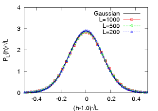
The dependence of the variance of on is plotted in Fig. 7.2 for systems of length , and . The data was obtained by averaging over avalanches. We plot versus , where differs from by an amount to take into account the corrections due to end effects. Then, for consistency, is replaced by . For the specific choice of and , we get a good collapse of the curves for different . We also show a fit to the proposed interpolation form in Eq. (7.24), with and . We see that the fit is very good.
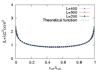
In order to check the logarithmic dependence of on for small , we re-plot the data in Fig. 7.3 using logarithmic scale for . We get a good collapse of the data for different , supporting our proposed dependence in Eq. (7.24).
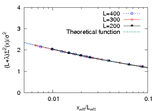
7.6 Concluding remarks
To summarize, we have studied the emergence of quasi-units in the one-dimensional Zhang sandpile model. The variance of height variables in the steady state is governed by the balance between two competing processes. The randomness in the drive i.e., the height of addition, tends to increase the variance in time. On the other hand, the topplings of height variables tend to equalize the excess height by distributing it to the nearby sites. There are on an average topplings per avalanche. Hence, in one dimension there are, on an average, topplings per site per avalanche. For large system size, the second process dominates over the first and the variance becomes low. We have shown that the variance vanishes as with increasing system size and the probability distribution of height concentrates around a non-random value which depends on the height of addition. We have also proposed a functional form for the spatial dependence of variance of height which incorporates the correct limiting behaviors, and matches very well with the numerical data.
An interesting question is whether one can extend these arguments to the two-dimensional Zhang model. There is some numerical evidence for the sharpening of height peaks as the system size is increased [lubeck]. In the simplest scenario [lubeck], there are peaks located at multiples of the quasi-unit , where is the lattice coordination number. This would imply that the asymptotic behavior of the two dimensional Zhang model is same as the height type BTW model in two dimension. However, this simple scenario can not be fully correct. During an avalanche, there is a finite probability that a site receives height from two neighbors in the previous time-step. If the height at the site before was , it will tranfer an height approximately equal to to its neighbors. As such events occur with nonzero probability, in the one site height distribution function, there would have to be peaks around , also. These peaks then give rise to other peaks. With many peaks, the definition of the width of a peak becomes somewhat ambiguous. As the number of topplings per site varies only as , the width is expected to decrease much more slowly with than in one dimension.
Chapter 8 Stochastic sandpile models
Based on the paper [myjsp1] by Tridib Sadhu and Deepak Dhar.
-
Abstract:
In this chapter, we study the steady state of the abelian sandpile models with stochastic toppling rules. The particle addition operators commute with each other, but in general these operators need not be diagonalizable. We use their abelian algebra to determine their eigenvalues, and the Jordan block structure. These are then used to determine the probability of different configurations in the steady state. We illustrate this procedure by explicitly determining the numerically exact steady state for a one dimensional example, for systems of size , and also study the change in density of particles along the lattice, in the steady state.
8.1 Introduction
Sandpile models with stochastic toppling rules are important subclass of sandpile models [dharphysica06]. The first such model was studied by Manna [manna], and these are usually known as Manna models in the literature. They are able to describe the avalanche behavior seen experimentally in the piles of granular media much better than the deterministic models [osloexpt]. Also, in numerical studies, one gets better scaling collapse, and consequently, more reliable estimates for the values of the critical exponents, than for models with deterministic toppling rules [stochnum].
Unfortunately, the theoretical understanding of models with stochastic toppling rules is much less than that of their deterministic counterparts, e.g. the Bak-Tang -Wiesenfeld (BTW) model [btw]. For example, there is no analogue of the burning test to distinguish the transient and the recurrent states of a general Manna model. For the deterministic case, it is known that all the recurrent configurations occur with equal probability in the steady state. A similar characterization of the steady state is not known in the Manna case. The steady state has been explicitly determined only for the fully directed stochastic models [asap, rittenberg, kloster, paczuski]. In some cases, one can formally characterize the recurrent states of the model, e.g. the -dimensional Oslo rice pile model, but a straightforward direct depth-first calculation of the exact probabilities of different configurations in the steady state takes steps where is the system length [dharoslo]. While the exact values of the critical exponents have been conjectured for dimensional directed Manna model [kloster, paczuski], the prototypical undirected Manna model in one dimension has resisted an exact solution so far [dickman1, dickman2, dickman3]. In higher dimensions, most of the studies are only numerical.
The conditions under which different scaling behaviors are seen in stochastic models is a long debated issue. Initial studies suggested that the stochastic sandpile model and the BTW model exhibit similar scaling behavior [guilera, pietronero, vespignani]. However later large scale simulations showed that the stochastic sandpile models constitute a universality class different from their deterministic counterparts: the critical exponents, scaling functions and geometrical features are different for the two classes of models [biham, lubeck1, milshtein, lubeck3, tebaldi, campelo]. Further evidence came from the qualitative differences in their avalanche distribution which has a multi-fractal nature for BTW model, whereas it follows simple finite size scaling [dickman1, tebaldi, campelo] for the Manna model. Also the directed version of the above models exhibit different scaling behavior than their undirected counterparts [satorras]. Numerical results suggest that both the abelian and non-abelian Manna model constitute a universality class [biham2] different from Directed-Percolation (DP) [bonachela1]. However, the corresponding fixed points are unstable with respect to introduction of perturbation (“stickiness”) and with stickiness the critical behavior flows to the DP universality class [mohanty1, bonachela2, mohanty2]. While there is a controversy about the generic DP behavior of undirected stochastic sandpile models; for the directed case, the numerical evidence for asymptotic DP behavior is quite convincing.
While the original Manna model did not have the abelian property of the BTW model, one can construct stochastic toppling rules with abelian property [sasm]. In this paper, we discuss this abelian version of the stochastic Manna model. We shall use the terms Deterministic abelian Sandpile Models (DASM) (see Ch. 3) and Stochastic abelian Sandpile Models (SASM), if we need to distinguish between these two classes of models. In DASM the relaxation rules satisfy pair wise balance [barma], which makes the model analytically tractable and the recurrent configurations become equally probable in the steady state. However the stochastic models do not have this property, and the steady state can not be determined easily.
We use the algebra of the addition operators to determine the steady state of the model. This algebraic approach provides a computationally efficient method to determine the Markov evolution matrix of the model. The addition operators of SASM are not necessarily diagonalizable even if we restrict ourselves to the space of recurrent configurations. Using the abelian algebra we determine a generalized eigenvector basis in which the operators reduce to Jordan block form. We also define a transformation matrix between this basis and the configuration basis, and express the steady state in the latter. This procedure is illustrated by explicitly working out the case of a one dimensional Manna model. In this special case, we can show that each Jordan block is at most of dimension . We determine the numerically exact steady state of the model for systems of size up to and determine the asymptotic density profile by extrapolating the results.
This chapter is organized as follows: In section 8.2, we define the model precisely. In section 8.3 we recapitulate the algebra of addition operators for DASM, and use it to determine the steady state. For the stochastic models same definition for the addition operators does not work and need to be redefined. We do this in section 8.4, and discuss their algebra. Calculation of the eigenvalues and the Jordan block structure of the addition operators are given in section 8.5. The transformation matrix between the generalized eigenvector basis and the configuration basis is determined in section 8.6, and is used to determine the steady state vector in the configuration basis in section 8.7. The exact numerical determination of the steady state is discussed in section 8.8 with some concluding remarks in section 8.9.
8.2 The Model
We define a generalized Manna model on a graph of sites with a non-negative integer height variable defined at each site . Let the threshold height at be , and the site is unstable if . If the system is stable, a sand grain is added at a randomly chosen site which increases the height by . For each site , there is a set of lists with . If a site is unstable, it relaxes by the following toppling rule: we decrease its height by . Then, with probability , we select the list , independent of any previous selections, and then add one grain to each site in that list. If a site occurs more than once in the list, we add that many grains to that site.
Toppling at a site can make other sites unstable and they topple in their turn, until all the lattice sites are stable. Using an argument given in [sasm], it can be easily shown that the above toppling rule is abelian. Then, it follows from the abelian property that the probabilities of different final stable configurations are independent of the order in which different unstable sites are toppled.
We illustrate these rules with some examples below.
-
•
Model A (The one dimensional Manna model): The graph is sites on a line and , for all sites. On toppling each grain is transfered to its neighbors with equal probability. Hence we have , for all , with , , and and and . Also grains can move out of the system if toppling occurs at a boundary site.
-
•
Model B (The one dimensional dissipative Manna model): Same as model A except that on toppling a grain can move out of the system with probability . Then and the lists of neighbors , , , , and , where is an empty set. The corresponding probabilities are , , and .
In this case, one can use periodic boundary conditions, as there is dissipation at all sites. the steady state is critical only in the limit . For the models A and B, it is easy to see that all stable configurations occur in the steady state with non-zero probability. We can also define stochastic models where the recurrent configurations form only an exponentially small fraction of all stable configurations. An example of this type is
-
•
Model C: The graph is a square lattice with sites and . Under toppling, with equal probability two particles are transfered to either horizontal or vertical neighbors. Hence with and with .
In the following we will mostly confine ourselves to Model A. Extensions to other cases present no special difficulties.
8.3 Determination of the steady state for a DASM
Before we carry out the analysis of the SASM, we recapitulate how the steady state for the DASM, defined in section 3.2.1, can be determined using the operator algebra of addition operators [dharphysica06]. Let us denote the space of stable states (see section 3.2.1) in the DASM as spanned by basis vectors labeled by . We define as the probability of finding the system in the basis at time . The time is in driving steps, i.e., it increases by one when a grain is added and the system is fully relaxed. To each set , we associate a vector belonging to the vector space , and write
| (8.1) |
This defines a state of the system at time . Recall that, in section 3.2.1, we have defined the particle addition operators , for all , which correspond to adding a sand grain at site when the system is in state configuration , and relaxing it until a stable configuration is reached. Thus, these are linear operators which act on the vector space and maps a configuration , in it, to another configuration , which is reached by the avalanche.
The time-evolution of the system is Markovian [vkampen] and the evolution operator is defined by the master equation
| (8.2) |
We can write the time-evolution operator in terms of the addition operators as
| (8.3) |
where is the number of sites on the lattice. To solve the time evolution, in general, we have to diagonalize the evolution operator . Now, we have shown in section 3.2.1, that the addition operators commute with each other. Then all the addition operators and hence, also have a common set of eigenvectors. Let be one such simultaneous eigenvector of the operators , with eigenvalues , respectively. Then
| (8.4) |
Recall the definition of the toppling matrix , introduced in section 3.2.1, for the DASM. Then, from the toppling rule, one can easily show, that
| (8.5) |
Also, recall, we have shown in section 3.2.1, that within the recurrent state space, each addition operator has an inverse. Then, the above relation can be written as
| (8.6) |
Applying the LHS to the eigenvector gives , for every , so that , where ’s are arbitrary integers. Then inverting,
| (8.7) |
where is the inverse of .
The particular eigenstate , corresponding to for all , is invariant under the action of all the ’s, i.e., . Thus this must be the stationary state of the system.
8.4 Algebra of the addition operators for SASM
We use the same notations, as in the last section, but this time for a SASM. So, is the space of stable states and is a stable height configuration constituting a complete set of basis vectors.
For stochastic toppling rules, the resulting state from the action of on a basis vector , is not necessarily another basis vector, but a linear combination of them. So, the addition operators have to be redefined. If the resulting configuration is with probability , we define
| (8.8) |
for all . Note that the action of any of these operators on a given configuration gives a unique probability state vector.
Eq. (8.8) is a formal definition of the operators . One can think of these as matrices, but, unlike the DASM, it is quite non-trivial to actually determine the matrix elements explicitly from the toppling rules. This is because of the non-zero probability of an arbitrary large number of toppling before a steady state is reached.
For an example, consider the avalanches in model A for system of size . Consider the stable configurations as the basis vectors and denote them by their height values . The action of on will generate a unstable state . Using the toppling rules we can write the following set of equations for three unstable states
| (8.9) |
We see that there is a nonzero probability that the avalanche can continue for more than toppling, for any finite . e.g. in the sequence . Thus straight forward application of the relaxation rules does not result in a finite procedure to determine the unstable vector in terms of the stable configurations. Instead, we have to write Eq. (8.9) as a matrix equation
| (8.10) |
and then invert it. More generally, the determination of involves working in a larger space of unstable configurations.
For example in model A, there are stable configurations, where each site has or particle. Total number of particles is at most . On adding one particle, the number of particles can become , where initially, only one site will have height . However, it is easy to verify that by toppling one can generate configurations where the number of particles at a site is much greater than . In fact, all the particles could be at the same site. Then the total number of stable and unstable configurations is the number of ways one can distribute or less particles on sites. It is easily seen that varies as , and one needs to invert a matrix of size .
There are models, generally known as the restricted sandpile models [restr1, restr2, restr3], where the toppling rules ensure that the heights do not exceed a fixed value. For these, the space of allowed configurations is much smaller. However, the height restriction makes the model non-abelian.
In this chapter we will use the operator algebra to obtain an efficient method to determine the probabilities explicitly which requires inverting a matrix only of size . It has been shown [sasm] that the addition operators for different sites commute i.e.
| (8.11) |
The proof uses the fact that any stochastic toppling event can be simulated by a pseudo-random generator. This essentially makes the toppling deterministic, which has the abelian property.
However, unlike the DASM, the inverse operators for SASM need not exist, even if we restrict ourselves to the set of recurrent configurations. This is because among the recurrent states, one can have two different initial probability vectors that yield the same resultant vector. This makes the determination of the matrix form of the operators difficult for this model.
Apart from the abelian property, the operators also satisfy a set of algebraic equations, like the Eq. (8.5) in DASM. For simplicity of presentation, now on we consider and for all sites. Then consecutive addition of grains at a site ensures that the site will topple once and transfers grains to its neighbors, irrespective of the initial height. Then the operators obey the following equation
| (8.12) |
where we have used the notation for any list , and
| (8.13) |
for sites outside the lattice. In particular for the examples in section 8.4, these equations are as follows
| (8.14) | |||||
| (8.15) | |||||
| (8.16) |
8.5 Jordan Block structure of the addition operators
In general the matrices need not be diagonalizable. However, using the abelian property, we can construct a common set of generalized eigenvectors for all the operators such that in this basis the matrices simultaneously reduce to Jordan block form. These generalized eigenvectors split the vector space into disjoint subspaces, each corresponding to distinct set of eigenvalues.
Lemma 8.5.1
There will be at least one common eigenvector in each subspace, for all the addition operators.
-
Proof
Consider one of the operators, say . Let be the subspace of spanned by the (right) generalized eigenvectors of corresponding to the eigenvalue . There is at least one such generalized eigenvector, so is non-null. We pick one of the other addition operators, say . From the fact that commutes with , it immediately follows that acting on any vector in the subspace leaves it within the same subspace. Diagonalizing within this subspace, we construct a possibly smaller but still non-null subspace which is spanned by simultaneous generalized eigenvectors of and with eigenvalues and . Repeating this argument with the other operators, one can construct vectors which are simultaneous eigenvectors of all the .
Let be such an eigenvector, with
| (8.17) |
Then from Eq.()the eigenvalues satisfy the following set of equations
| (8.18) |
where we have used the notation , for any list .
Rather than work with this general case, we will consider the special case in model A for simplicity. No extra complications occur in the more general case. Then, from Eq.(8.14), the corresponding eigenvalue equation is
| (8.19) |
These are L coupled quadratic equations in complex variables . We can reduce them to linear equations by taking square root
| (8.20) |
where . The Eq. (8.13) sets the values for the eigenvalues of and which are
| (8.21) |
There are different choices for the set of different ’s and for each such choice, we get a set of eigenvalues . In general, there will be degenerate sets of eigenvalues and the degeneracy arises if one of the is zero. Using the triangular inequality in (8.20) we get
| (8.22) |
i.e. are convex functions of discrete variables . Then, given the boundary condition in Eq. (8.21), there could at most be one in the solution for a given , which means that each eigenvalue set can be at most doubly degenerate.
Finding the number of degeneracies of solutions is interesting but difficult in general. We show that
Lemma 8.5.2
For (mod ) the number of degenerate sets of eigenvalues .
-
Proof
Consider the system of length , with being a non negative integer. For any given set , to , it is possible to construct a solution of Eq. (8.20) with which satisfies and . Clearly, from Eq.(8.20), if we have the solution corresponding to a particular set , one can construct the solution corresponding to using . Using this symmetry we extend ( to ) to form a set for to as follows:
(8.23) (8.24) This is a solution of Eq.(8.20) for the set with
(8.25) (8.26) and this solution satisfies the boundary conditions , , and (Fig.). There are such solutions possible corresponding to all possible sets of , and this gives the lower bound for the number of degenerate solutions.
A direct numerical calculation for shows that if (mod ), all sets of eigenvalues are distinct. We present the degeneracies of the solutions in Table.. Calculation for simple choices of shows that the degeneracies are possible only if (mod ).
For example, consider for and for the rest of the sites it is . Then is of the form , for all . If we want this to be zero for , we must have . Then, requiring that the equation (8.20) be satisfied at , gives , i.e. (mod ). Similarly for the set with and for rest of the sites imposes a condition on length , which is also a subset of (mod ). Finding a general proof that degeneracies occur only if (mod ) remain an open problem.
For each degenerate subspace there is a generalized eigenvector linearly independent of the eigenvector corresponding to the eigenvalue of the subspace. In general, let us denote them by , where for the eigenvector and for the generalized eigenvector. For non-degenerate subspace can only be . The vectors satisfy the following equations
| (8.27) |
where ’s are complex numbers. Then using the Eq. (8.20) it can be shown easily that ’s satisfy the following equation
| (8.28) |
This is similar to the Eq. (8.20), except the boundary conditions which are
| (8.29) |
For a given set of , these are simultaneous set of homogeneous linear equations. If is a solution, then is also a solution. Thus there are infinitely many possible solutions, each corresponding to different choices of . In order to get a single solution we choose if , without loss of generality. This corresponds to choosing a particular normalization of the rank eigenvectors. The solution of both the equations (8.20) and (8.28) can be easily obtained numerically. The generalized eigenvectors and the Jordan block form of the addition operators for the system of size are given in the appendix.
| L | |||||||||||
|---|---|---|---|---|---|---|---|---|---|---|---|
| 3 | 4 | 0 | 4 | ||||||||
| 7 | 40 | 0 | 0 | 8 | 24 | ||||||
| 11 | 136 | 0 | 0 | 0 | 8 | 0 | 120 | ||||
| 15 | 1304 | 0 | 0 | 0 | 4 | 32 | 48 | 288 | 560 | ||
| 19 | 3024 | 0 | 0 | 0 | 0 | 0 | 8 | 0 | 288 | 0 | 2432 |
8.6 Matrix representation in the configuration basis
Given the well-defined action of the addition operators on the generalized eigenvectors it is possible to define a transformation matrix between the configuration basis and the generalized eigenvector basis.
| (8.30) |
where is the basis vector of corresponding to the height configuration and is the th generalized eigenvector. Let us express the configuration , with all sites empty, as a linear combination of all the generalized eigenvectors.
| (8.31) |
where s are constants. Then all the stable configurations can be obtained by adding grains at properly chosen sites in .
| (8.32) |
and hence
| (8.33) |
The action of the addition operators on the generalized eigenvectors, for example Eq.(8.27) for model A, would generate the elements of the matrix . Given , we can get the eigenvectors of , in the configuration basis, in particular, the steady state vector, by the inverse transformation
| (8.34) |
The addition operators in the configuration basis are obtained using the similarity transformation . An explicit form of for model A of length is given in the appendix.
8.7 Determination of the steady state vector
Just like the DASM in section 8.3, the time-evolution of the system is Markovian and the evolution operator can be written in terms of the addition operators as
| (8.35) |
Then the common eigenvector of all the addition operators corresponding to eigenvalue is the steady state vector of the system. The steady state vector can be determined in the stable configuration basis using the matrix . For model A of length the steady state vector is
| (8.36) | |||||
where the stable configurations are denoted by with as the height of the th site. The amplitude of each term in the expansion is the probability of finding the corresponding height configuration in the steady state.
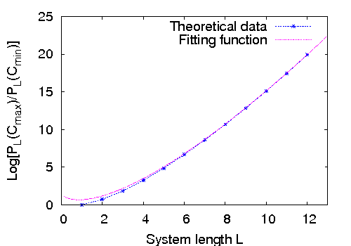
8.8 Numerical Results
Here we describe the results of numerical calculations for the exact steady state of model A for different system lengths and discuss its properties. As shown in Eq. (8.20) and Eq. (8.28) the eigenvalues and the off-diagonal matrix elements form sets of linear equations for a given set of . We solve them by LU decomposition method. Because of the tridiagonal structure of the equations, only number of steps are required to get the solution. The maximum number of steps () are required for the inversion of the transformation matrix . We have used the Gauss-Jordan elimination method for the inversion. It is important to note that, the maximum system length , possible to treat by this method, is determined by the limited memory of the computers, and not by the computation time. Using desktop computers we were able to determine exactly for systems of size .
We note that as is increased, the second largest eigenvalue of tends to . Thus, the gap between the largest and the next largest eigenvalue of the relaxation matrix does not tend to zero. This gap measures the relaxation time of the system in terms of the macro-time unit of interval between addition of grains. However, the average duration of an avalanche measured in terms of micro-time unit of duration of a single toppling event does diverge, as system size increases.
An interesting question is the extent of variation between probabilities of different configurations in the steady state. In the one-dimensional Oslo model, for a system of sites, the ratio of probabilities of the most probable to the least probable configuration varies as [dharoslo]. However in model A, we find that the ratio is not quit as large, and it only varies approximately as (Fig.8.2) for large .
This suggests that the exact steady state is not a product measure state. To check this we define a product basis , where could be any one of the two orthogonal vectors
| (8.37) |
with a real number. Then in this basis the steady state can be written as
| (8.38) |
We choose so that the ratio between the amplitudes of basis vectors with next-largest and largest amplitudes becomes as small as possible (this would become zero, if the state was a product measure state). In Fig.8.3, we have plotted for system of size , the relative amplitudes in both configuration basis and the optimized product basis as a function of the rank of the basis vectors with the vectors arranged in decreasing orders of their amplitudes. In the optimized basis the second highest probability is only times smaller than the highest probability. This shows that the steady state measure is not a product measure.
| 2 | 0.583333 | 0.583333 |
|---|---|---|
| 3 | 0.634354 | 0.709184 |
| 4 | 0.669262 | 0.737000 |
| 5 | 0.695210 | 0.769704 |
| 6 | 0.715472 | 0.786491 |
| 7 | 0.731879 | 0.805897 |
| 8 | 0.745514 | 0.816009 |
| 9 | 0.757080 | 0.827217 |
| 10 | 0.767051 | 0.834600 |
| 11 | 0.775760 | 0.842665 |
| 12 | 0.783451 | 0.848054 |
| L | |||
|---|---|---|---|
| 3 | 1.061 | 1.128 | 0.656 |
| 4 | 1.049 | 1.132 | 0.641 |
| 5 | 1.053 | 1.132 | 0.646 |
| 6 | 1.049 | 1.131 | 0.640 |
| 7 | 1.050 | 1.131 | 0.641 |
| 8 | 1.049 | 1.130 | 0.639 |
| 9 | 1.049 | 1.130 | 0.639 |
| 10 | 1.049 | 1.130 | 0.639 |
| 11 | 1.049 | 1.130 | 0.639 |
The steady state density for different sites are plotted in Fig. 8.4 for different system sizes. Amongst the different fitting forms that we tried, the following functional form gives the best fit
| (8.39) |
where and are real numbers. Using this functional form the steady state particle density averaged over all sites for system of size can be written as
| (8.40) |
where is a real number and is the asymptotic value of the average particle density. The exact value of and the particle density at the central site are listed in the Table for different system sizes. The sequential fitting method is used to find the values of , , and from these data. For a given choice of , these values are obtained numerically by solving the Eq. (8.40) for three consecutive lengths , and . Best convergence of the values of , and are obtained for , which are tabulated in Table . The asymptotic value of the average particle density converges to which is close to the more precise estimate , from Monte Carlo simulations [dickman1].
8.9 Concluding remarks.
For a general SASM with sites, the calculation of eigenvalues involves solving coupled polynomial equations in variables. This can be done in time polynomial in , the number of stable configurations of the model. These are then used to construct the transformation matrix of size . Finally inverting the matrix gives us the eigenvectors of the evolution operator, in particular the steady state.
Of course, to determine the steady state of any Markov chain on states, we need to determine the eigenvectors of the evolution matrix of size . The point here is that the specification of the toppling rules does not directly specify the evolution matrix, and determining the matrix elements of the latter from the toppling rules is computationally very nontrivial. Using the abelian property, we are able to tackle this problem.
For a generic model with some parameters, e.g. the model B, except for special symmetries, one does not expect degeneracies in eigenvalues to occur for a generic value of the parameters. For special values of the parameters, if there is a non-trivial Jordan block structure of the evolution operator, it would show up in the time-dependent correlation functions of the model by the presence of terms of the type , in addition to the usual sum of terms of the type .
In particular we have explicitly calculated the steady state for a specific model (model A in section 2) of length L. Extrapolating the results we determined the asymptotic density profile in the steady state. The power-law profile of deviations from the mean value near the ends would be important for determining the avalanche exponents of the model [lubeck4]. This remains an interesting open problem.
Appendix A Solution of Laplace’s equation on hexagonal lattice
We follow the calculation given in [atkinson]. Let be the solution of the Poisson equation
| (A.1) |
defined on a lattice, where the sum is carried over the nearest neighbors of the vertex and is the total number of them. For a hexagonal lattice and for a triangular lattice . Clearly a hexagonal lattice can be constructed from a triangular lattice by a transformation as shown in the Fig.A.1. Let and are the solutions of the Poisson equation with same defined at the common vertices and for the additional vertices in the hexagonal lattice. It is easy to check that for the common vertices and for the additional ones the solution is the average of its value at the neighboring sites (see Fig.A.2). We first detrmine and then use the relation to determine .
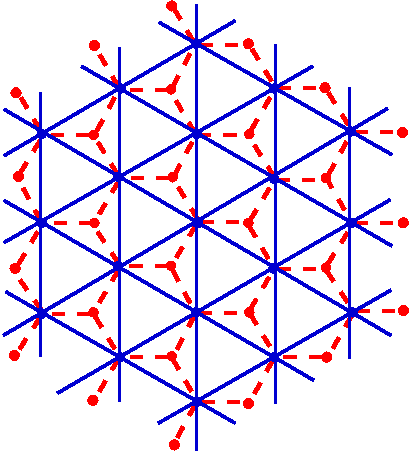
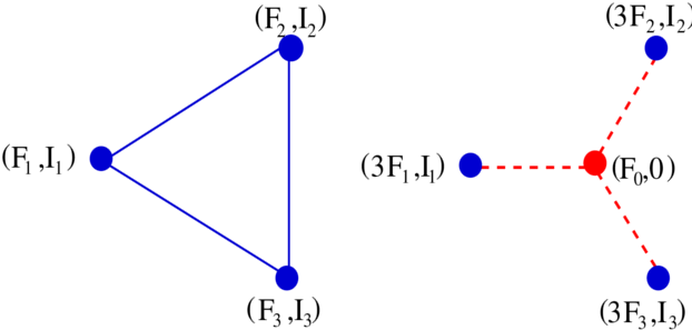
Consider a triangular lattice with lattice edges of length . Each vertex on the lattice is denoted by a pair of integers where the complex coordinate of a site is
| (A.2) |
with even. The Poisson equation on this lattice is
| (A.3) |
Define the discrete Fourier transformation
| (A.4) |
| (A.5) |
Using the expression in equation A.5 it can be shown that
| (A.6) |
where is the discrete Fourier transformation of . We are interested in a solution with , where is normalization constant. Also considering the condition that the function , at the origin, it can be shown that
| (A.7) |
Using the relation between and and with a simple change of variables we get the expression in equation 6.21.
Appendix B Relation to the theory of discrete analytic functions
The sandpile patterns we studied are characterized in terms of discrete analytic functions (DAF) on different discretizations of the complex plane. For the pattern in Fig. 6.10, it is the DAF on a hexagonal lattice, which increases logarithmically at large distances as in Eq. (6.27).
Studies of DAF started with the work of Kirchhoff on resistor networks [hu, cserti, Doyle], and has been studied subsequently by many others [duffin, mercat]. However, we have not encountered any work on DAF on many sheeted Riemann surfaces. In the following we present a way to determine DAF on a square discretization of Riemann surfaces.
Consider a square grid of points , where are integers and is the lattice spacing. Let be a complex function defined at every site on the grid. The function is defined to be discrete analytic [laszlo] if it satisfies the discrete Cauchy Riemann condition
| (B.1) |
at all elementary squares on the grid as shown in Fig. B.1.
In complex analysis, simple examples of analytic functions are , and any polynomial of is also analytic. For DAF, it is clear, using the linearity of equation (B.1), that sum of DAF is also discrete analytic. However, not all positive integer powers of are discrete analytic. It is easy to check that the functions , , , are discrete analytic, but is not. We can however construct polynomial functions of and , that are discrete analytic. Two such examples are and .
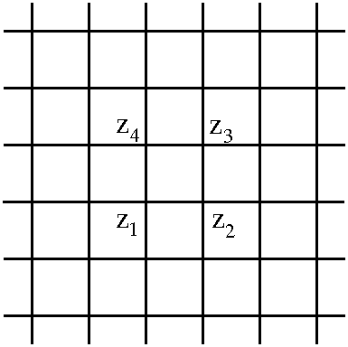
We define a function as a homogeneous polynomial in , and , of degree , which is a DAF. Using homogeneity, we have
| (B.2) |
and then using , we can express in terms of . This fixes up to a multiplicative constant. The normalization is fixed by requiring that as tends to zero, . Then using Cauchy Riemann conditions it is easily seen that , for all integers , has a series expansion in of the form
| (B.3) |
where
| (B.4) | |||||
| (B.5) | |||||
and so on. For an integer , this series will terminate after a finite number of terms, and all of them can be determined iteratively.
It is possible to analytically continue the functions for rational values of . For example,
| (B.7) |
Then, this analytic continuation of provides us the discrete analytic functions which in the limit grows as , for any real positive values of . It is interesting to note that the function , used in [myepl] to characterize the pattern in Fig. 1.3(b), is equal to , up to a multiplicative constant. The patterns in the presence of a line of sinks, or near wedges studied in [myjsp] involve other rational values. For example, for the pattern near a line sink, one requires the function .
Appendix C Solution of the Eq. (5.18)
Here we discuss the solution of the Eq. (7.18) for the starting values given by
| (C.1) |
We start with an ansatz , where both and are functions only of . This form satisfies the Eq. (7.18) for all , , if and satisfy
| (C.2) | |||||
| (C.3) |
To solve the Eq. (C.2), we first make a change of variable . In terms of , the equation becomes , which can be easily integrated to give
| (C.4) |
where is an integration constant. To satisfy the initial condition in Eq. (C.1), we choose
| (C.5) |
Similarly, to solve the equation for , we use the form of given in Eq. (C.4) and get
| (C.6) |
This can be integrated to give
| (C.7) |
where is an integration constant. Then the probability can be written as
| (C.8) |
where to satisfy the initial condition at , we have used the integration constant . Then, with these values of and , we have the solution for all , , given by
| (C.9) | |||||
Now, as satisfies the Eq. (7.18),
| (C.10) |
will also satisfy the equation for any natural number . In addition,
| (C.11) |
Hence, we see that the solution of the Eq. (7.18), starting with at is
| (C.12) |
for all , , where is given in Eq. (C.9) and is any natural number.
Appendix D Jordon Block for L=3 SASM
Here we give some details of the explicit calculation of the steady state, and the matrix representation of addition operators for model A of length .
The eight sets of eigenvalues obtained by solving Eq.(8.20) are , , , , , and with the last two sets repeated twice.
For writing the matrix structure of the addition operators, we choose the order of the eigenvectors same as the order of the eigenvalues mentioned above. For the degenerate subspace we order the eigenvector , defined in Eq.(8.27), before the generalized eigenvector . Then in this basis the matrices corresponding to the addition operators have the following Jordan block form.
| (D.1) |
| (D.2) |
| (D.3) |
The transformation matrix , discussed in section , between the generalized eigenvector basis and the configuration basis has the following form
| (D.4) |
where the configuration basis vectors are chosen in the following order , , , , , , , and . The matrix is non-singular, and the inverse can be calculated numerically. Using the similarity transformation we find matrix representation of the addition operator in the configuration basis.
| (D.5) |
The other operators can also be determined similarly.
Bibliography
- [AD95] Agha Afsar Ali and Deepak Dhar, Breakdown of simple scaling in abelian sandpile models in one dimension, Phys. Rev. E 51 (1995), no. 4, R2705–R2708.
- [Ali95a] Agha Afsar Ali, Self-organized criticality in a sandpile model with threshold dissipation, Phys. Rev. E 52 (1995), no. 5, R4595–R4598.
- [Ali95b] , Self-organized criticality in a sandpile model with threshold dissipation, Phys. Rev. E 52 (1995), no. 5, R4595–R4598.
- [AR08] F. C. Alcaraz and V. Rittenberg, Directed abelian algebras and their application to stochastic models, Phys. Rev. E 78 (2008), no. 4, 041126.
- [AS99] D. Atkinson and F.J.van Steenwijk, Infinite resistive lattices, Am. J. Phys. 67 (1999), no. 6, 486–492.
- [Bak96a] P. Bak, How nature works, first ed., ch. 1, p. 14, Copernicus, New York, 1996.
- [Bak96b] , How nature works, first ed., ch. 1, p. 31, Copernicus, New York, 1996.
- [BCF+01] Jayanth R. Banavar, Francesca Colaiori, Alessandro Flammini, Amos Maritan, and Andrea Rinaldo, Scaling, optimality, and landscape evolution, Journal of Statistical Physics 104 (2001), 1–48.
- [BCK97] Ph. Blanchard, B. Cessac, and T. Krüger, A dynamical system approach to soc models of Zhang’s type, Journal of Statistical Physics 88 (1997), 307–318.
- [BHB96a] A. Ben-Hur and O. Biham, Universality in sandpile models, Phys. Rev. Lett. 53 (1996), 1317–1320.
- [BHB96b] Asa Ben-Hur and Ofer Biham, Universality in sandpile models, Phys. Rev. E 53 (1996), no. 2, R1317–R1320.
- [BMM01] Ofer Biham, Erel Milshtein, and Ofer Malcai, Evidence for universality within the classes of deterministic and stochastic sandpile models, Phys. Rev. E 63 (2001), no. 6, 061309.
- [BMn08] Juan A. Bonachela and Miguel A. Muñoz, Confirming and extending the hypothesis of universality in sandpiles, Phys. Rev. E 78 (2008), no. 4, 041102.
- [BMQR08] A. F. Boer, R. Meester, C. Quant, and F. Redig, A probabilistic approach to Zhang’s sandpile model, Communications in Mathematical Physics 280 (2008), 351–388.
- [BN07] Matthew Baker and Serguei Norine, Riemann-roch and abel-jacobi theory on a finite graph, Advances in Mathematics 215 (2007), no. 2, 766 – 788.
- [BR02] Yvan Le Borgne and Dominique Rossin, On the identity of the sandpile group, Discrete Math. 256 (2002), no. 3, 775–790.
- [BRC+06] Juan A. Bonachela, José J. Ramasco, Hugues Chaté, Ivan Dornic, and Miguel A. Muñoz, Sticky grains do not change the universality class of isotropic sandpiles, Phys. Rev. E 74 (2006), no. 5, 050102.
- [BS93] Per Bak and Kim Sneppen, Punctuated equilibrium and criticality in a simple model of evolution, Phys. Rev. Lett. 71 (1993), no. 24, 4083–4086.
- [BTW87] P. Bak, C. Tang, and K. Wiesenfeld, Self-organized criticality: An explanation of the 1/f noise, Phys. Rev. Lett. 59 (1987), no. 4, 381–384.
- [CGMP09] L. Corté, S. J. Gerbode, W. Man, and D. J. Pine, Self-organized criticality in sheared suspensions, Phys. Rev. Lett. 103 (2009), no. 24, 248301.
- [CPS08] Sergio Caracciolo, Guglielmo Paoletti, and Andrea Sportiello, Explicit characterization of the identity configuration in an abelian sandpile model, Journal of Physics A: Mathematical and Theoretical 41 (2008), no. 49, 495003.
- [Cre91] M. Creutz, Abelian sandpiles, Comput. Phys. 5 (1991), 198–203.
- [Cse00] József Cserti, Application of the lattice green’s function for calculating the resistance of an infinite network of resistors, Amer. J. Phys. 68 (2000), no. 10, 896–906.
- [CVZ99] A. Chessa, A. Vespignani, and S. Zapperi, Critical exponents in stochastic sandpile models, Computer Physics Communications 121-122 (1999), 299 – 302.
- [DAAMn+01] Ronald Dickman, Mikko Alava, Miguel A. Muñoz, Jarkko Peltola, Alessandro Vespignani, and Stefano Zapperi, Critical behavior of a one-dimensional fixed-energy stochastic sandpile, Phys. Rev. E 64 (2001), no. 5, 056104.
- [DBM95] G. Durin, G. Bertotti, and A. Magni, Fractals, scaling and the question of self-organized criticality in magnetization processes, Fractals 3 (1995), no. 2, 351–370.
- [DC03] R. Dickman and J. M. M. Campelo, Avalanche exponents and corrections to scaling for a stochastic sandpile, Phys. Rev. E 67 (2003), no. 6, 066111.
- [DD97] Deepak Dhar and Abhishek Dhar, Distribution of sizes of erased loops for loop-erased random walks, Phys. Rev. E 55 (1997), no. 3, R2093–R2096.
- [Dha90] Deepak Dhar, Self-organized critical state of sandpile automaton models, Phys. Rev. Lett. 64 (1990), no. 14, 1613–1616.
- [Dha99a] D. Dhar, Studying Self-Organized Criticality with Exactly Solved Models, arXiv:cond-mat/9909009 (1999).
- [Dha99b] Deepak Dhar, The abelian sandpile and related models, Physica A: Statistical Mechanics and its Applications 263 (1999), no. 1-4, 4 – 25.
- [Dha99c] , Some results and a conjecture for manna’s stochastic sandpile model, Physica A: Statistical Mechanics and its Applications 270 (1999), no. 1-2, 69 – 81.
- [Dha04] , Steady state and relaxation spectrum of the Oslo rice-pile model, Physica A: Statistical Mechanics and its Applications 340 (2004), no. 4, 535 – 543.
- [Dha06] , Theoretical studies of self-organized criticality, Physica A: Statistical and Theoretical Physics 369 (2006), no. 1, 29 – 70.
- [Dic06] Ronald Dickman, Critical exponents for the restricted sandpile, Phys. Rev. E 73 (2006), no. 3, 036131.
- [DM90] D Dhar and S N Majumdar, Abelian sandpile model on the bethe lattice, Journal of Physics A: Mathematical and General 23 (1990), no. 19, 4333.
- [DMS00] Mario De Menech and Attilio L. Stella, From waves to avalanches: Two different mechanisms of sandpile dynamics, Phys. Rev. E 62 (2000), no. 4, R4528–R4531.
- [DP04] D. Dhar and P. Pradhan, Probability distribution of residence times of grains in sand-pile models, Journal of Statistical Mechanics: Theory and Experiment 2004 (2004), no. 05, P05002.
- [DR99] Peter Sheridan Dodds and Daniel H. Rothman, Unified view of scaling laws for river networks, Phys. Rev. E 59 (1999), no. 5, 4865–4877.
- [DS84] Peter G. Doyle and J. Laurie Snell, Random walks and electric networks, Mathematical Association of America, Washington, DC, 1984.
- [DS86] B. Duplantier and H. Saleur, Exact surface and wedge exponents for polymers in two dimensions, Phys. Rev. Lett. 57 (1986), no. 25, 3179–3182.
- [DS92] B. Drossel and F. Schwabl, Self-organized critical forest-fire model, Phys. Rev. Lett. 69 (1992), no. 11, 1629–1632.
- [DSC09] D. Dhar, T. Sadhu, and S. Chandra, Pattern formation in growing sandpiles, Europhys. Lett. 85 (2009), no. 4, 48002.
- [dSdO09] Evandro F da Silva and Mário J de Oliveira, An asymmetric sandpile model with height restriction, Journal of Physics A: Mathematical and Theoretical 42 (2009), no. 38, 385003.
- [dSV92] Maria de Sousa Vieira, Self-organized criticality in a deterministic mechanical model, Phys. Rev. A 46 (1992), no. 10, 6288–6293.
- [DTdO02] Ronald Dickman, Tânia Tomé, and Mário J. de Oliveira, Sandpiles with height restrictions, Phys. Rev. E 66 (2002), no. 1, 016111.
- [Duf56] R. J. Duffin, Basic properties of discrete analytic functions., Duke Mathematical Journal 23 (1956), no. 2, 335–363.
- [FCMS+96] V. Frette, K. Christensen, A. Malthe-Sorenssen, J. Feder, T. Jossang, and P. Meakin, Avalanche dynamics in a pile of rice, nature 379 (1996), 49–52.
- [FdBR08] Anne Fey-den Boer and Frank Redig, Limiting shapes for deterministic centrally seeded growth models, Journal of Statistical Physics 130 (2008), 579–597.
- [Fei78] Mitchell J. Feigenbaum, Quantitative universality for a class of nonlinear transformations, Journal of Statistical Physics 19 (1978), 25–52.
- [FLP10] Anne Fey, Lionel Levine, and Yuval Peres, Growth rates and explosions in sandpiles, Journal of Statistical Physics 138 (2010), 143–159.
- [FV06] Maurizio Falcone and Stefano Finzi Vita, A finite-difference approximation of a two-layer system for growing sandpiles, SIAM Journal on Scientific Computing 28 (2006), no. 3, 1120–1132.
- [FWNL95] Stuart Field, Jeff Witt, Franco Nori, and Xinsheng Ling, Superconducting vortex avalanches, Phys. Rev. Lett. 74 (1995), no. 7, 1206–1209.
- [GDG98] Achille Giacometti and Albert Díaz-Guilera, Dynamical properties of the Zhang model of self-organized criticality, Phys. Rev. E 58 (1998), no. 1, 247–253.
- [GH02] G. Pruessner and H. Jeldtoft Jensen, A solvable non-conservative model of self-organised criticality, Europhys. Lett. 58 (2002), no. 2, 250–256.
- [GQ00] J. Gravner and J. Quastel, Internal DLA and the stefan problem., Ann. Prob. 28 (2000), no. 4, 1528–1562.
- [GR56] B. Gutenberg and C. F. Richter, Ann. Geophysics. 9 (1956), 1.
- [GZ96] Peter Grassberger and Yi-Cheng Zhang, Self-organized formulation of standard percolation phenomena, Physica A: Statistical and Theoretical Physics 224 (1996), no. 1-2, 169 – 179.
- [Her86a] H. J. Herrmann, Geometrical cluster growth models and kinetic gelation, Physics Reports 136 (1986), no. 3, 153 – 224.
- [Her86b] H. J. Herrmann, Geometrical cluster growth models and kinetic gelation, Physics Reports 136 (1986), no. 3, 153 – 224.
- [HK99] K. P. Hadeler and C. Kuttler, Dynamical models for granular matter., vol. 2, pp. 9–18, Springer-Verlag, Berlin, 1999.
- [J9́0] Imre M. Jánosi, Effect of anisotropy on the self-organized critical state, Phys. Rev. A 42 (1990), no. 2, 769–774.
- [J.98] Jensen H. J., Self-organized criticality: Emergent complex behavior in physical and biological systems, Cambridge University Press, 1998.
- [JLN89] H. M. Jaeger, Chu-heng Liu, and Sidney R. Nagel, Relaxation at the angle of repose, Phys. Rev. Lett. 62 (1989), no. 1, 40–43.
- [JNB96] Heinrich M. Jaeger, Sidney R. Nagel, and Robert P. Behringer, Granular solids, liquids, and gases, Rev. Mod. Phys. 68 (1996), no. 4, 1259–1273.
- [Kam07] NG Van Kampen, Stochastic processes in physics and chemistry, North Holland, 2007.
- [Kin85] W. Kinzel, Phase transitions of cellular automata, Zeitschrift für Physik B Condensed Matter 58 (1985), 229–244.
- [KMT01] Morten Kloster, Sergei Maslov, and Chao Tang, Exact solution of a stochastic directed sandpile model, Phys. Rev. E 63 (2001), no. 2, 026111.
- [KNWZ89] Leo P. Kadanoff, Sidney R. Nagel, Lei Wu, and Su-min Zhou, Scaling and universality in avalanches, Phys. Rev. A 39 (1989), no. 12, 6524–6537.
- [L9̈7] S. Lübeck, Large-scale simulations of the Zhang sandpile model, Phys. Rev. E 56 (1997), no. 2, 1590–1594.
- [L0̈0] , Moment analysis of the probability distribution of different sandpile models, Phys. Rev. E 61 (2000), no. 1, 204–209.
- [LD01] S. Lübeck and D. Dhar, Continuously varying exponents in a sandpile model with dissipation near surface, Journal of Statistical Physics 102 (2001), 1–14.
- [LE95] Barabasi L. and Stanley H. E., Fractal concepts in surface growth, Cambridge University Press, 1995.
- [LHG07] A. Levina, J. M. Herrmann, and T. Geisel, Dynamical synapses causing self-organized criticality in neural networks, Nat Phys 3 (2007), 857–860.
- [LKG90] S. H. Liu, Theodore Kaplan, and L. J. Gray, Geometry and dynamics of deterministic sand piles, Phys. Rev. A 42 (1990), no. 6, 3207–3212.
- [LLT91] S.-C. Lee, N. Y. Liang, and W.-J. Tzeng, Exact solution of a deterministic sandpile model in one dimension, Phys. Rev. Lett. 67 (1991), no. 12, 1479–1481.
- [Lov04] L. Lovsz, Discrete analytic functions: An exposition., second ed., pp. 241–273, Int. Press, Somerville, MA, 2004.
- [LP07] L. Levine and Y. Peres, Scaling limits for internal aggregation models with multiple sources, arXiv:0712.3378v2 (2007).
- [LP08] , Spherical asymptotics for the rotor-router model in , Indiana Univ. Math. J. 57 (2008), 431–450.
- [LP10] L. Levine and J. Propp, What is a sandpile?, Notices of the AMS 57 (2010), 976–979.
- [LU97a] S. Lübeck and K. D. Usadel, Numerical determination of the avalanche exponents of the Bak-Tang-Wiesenfeld model, Phys. Rev. E 55 (1997), 4095–4099.
- [LU97b] S. Lübeck and K. D. Usadel, Numerical determination of the avalanche exponents of the Bak-Tang-Wiesenfeld model, Phys. Rev. E 55 (1997), no. 4, 4095–4099.
- [Lüb00] S. Lübeck, Moment analysis of the probability distribution of different sandpile models, Phys. Rev. E 61 (2000), no. 1, 204–209.
- [Man91] S S Manna, Two-state model of self-organized criticality, Journal of Physics A: Mathematical and General 24 (1991), no. 7, L363.
- [MBS98a] E. Milshtein, O. Biham, and S. Solomon, Universality classes in isotropic, abelian, and non-abelian sandpile models, Phys. Rev. E 58 (1998), no. 1, 303–310.
- [MBS98b] Erel Milshtein, Ofer Biham, and Sorin Solomon, Universality classes in isotropic, abelian, and non-abelian sandpile models, Phys. Rev. E 58 (1998), no. 1, 303–310.
- [MD92] S.N. Majumdar and Deepak Dhar, Equivalence between the abelian sandpile model and the q–>0 limit of the Potts model, Physica A: Statistical Mechanics and its Applications 185 (1992), no. 1-4, 129 – 145.
- [MD02] P. K. Mohanty and Deepak Dhar, Generic sandpile models have directed percolation exponents, Phys. Rev. Lett. 89 (2002), no. 10, 104303.
- [MD07] P.K. Mohanty and Deepak Dhar, Critical behavior of sandpile models with sticky grains, Physica A: Statistical Mechanics and its Applications 384 (2007), no. 1, 34 – 38.
- [Mer01] C. Mercat, Discrete Riemann surfaces and the Ising model., Commun. Math. Phys. 218 (2001), 177–216.
- [MG97] S. S. Manna and D. Giri, Sandpile model with activity inhibition, Phys. Rev. E 56 (1997), no. 5, R4914–R4917.
- [MS00] M. D. Menech and A. L. Stella, From waves to avalanches: Two different mechanisms of sandpile dynamics, Phys. Rev. E 62 (2000), no. 4, R4528–R4531.
- [MT99] Bruce D. Malamud and Donald L. Turcotte, Self-organized criticality applied to natural hazards, Natural Hazards 20 (1999), 93–116.
- [MZ96] Sergei Maslov and Yi-Cheng Zhang, Self-organized critical directed percolation, Physica A: Statistical and Theoretical Physics 223 (1996), no. 1-2, 1 – 6.
- [OFC92] Zeev Olami, Hans Jacob S. Feder, and Kim Christensen, Self-organized criticality in a continuous, nonconservative cellular automaton modeling earthquakes, Phys. Rev. Lett. 68 (1992), no. 8, 1244–1247.
- [ORN98] C. J. Olson, C. Reichhardt, and Franco Nori, Fractal networks, braiding channels, and voltage noise in intermittently flowing rivers of quantized magnetic flux, Phys. Rev. Lett. 80 (1998), no. 10, 2197–2200.
- [Ost03] Srdjan Ostojic, Patterns formed by addition of grains to only one site of an abelian sandpile, Physica A: Statistical Mechanics and its Applications 318 (2003), no. 1-2, 187 – 199.
- [PB96] Maya Paczuski and Stefan Boettcher, Universality in sandpiles, interface depinning, and earthquake models, Phys. Rev. Lett. 77 (1996), no. 1, 111–114.
- [PB00] Maya Paczuski and Kevin E. Bassler, Theoretical results for sandpile models of self-organized criticality with multiple topplings, Phys. Rev. E 62 (2000), no. 4, 5347–5352.
- [PDDK96] V. B. Priezzhev, Deepak Dhar, Abhishek Dhar, and Supriya Krishnamurthy, Eulerian walkers as a model of self-organized criticality, Phys. Rev. Lett. 77 (1996), no. 25, 5079–5082.
- [Pea93] John E. Pearson, Complex Patterns in a Simple System, Science 261 (1993), no. 5118, 189–192.
- [PN06] Ole Peters and J. David Neelin, Critical phenomena in atmospheric precipitation, Nat Phys (2006), 393–396.
- [PPH03] A. M. Povolotsky, V. B. Priezzhev, and Chin-Kun Hu, The asymmetric avalanche process, Journal of Statistical Physics 111 (2003), 1149–1182.
- [Pri00] V. B. Priezzhev, The upper critical dimension of the abelian sandpile model, Journal of Statistical Physics 98 (2000), 667–684.
- [PSV00] Romualdo Pastor-Satorras and Alessandro Vespignani, Universality classes in directed sandpile models, Journal of Physics A: Mathematical and General 33 (2000), no. 3, L33.
- [PZL+05] Gui-Jun Pan, Duan-Ming Zhang, Zhi-Hua Li, Hong-Zhang Sun, and Yan-Ping Ying, Critical behavior in non-abelian deterministic directed sandpile, Physics Letters A 338 (2005), no. 3-5, 163 – 168.
- [RA00] R. Pastor-Satorras and A. Vespignani, Anomalous scaling in the Zhang model, Eur. Phys. J. B 18 (2000), no. 2, 197–200.
- [RMAS00] R. Dickman, M.A. Muñuz, A. Vespignani, and S. Zapperi, Paths to self-organised criticality, Brazilian Journal of physics 30 (2000), no. 1, 27–41.
- [RS92] P Ruelle and S Sen, Toppling distributions in one-dimensional abelian sandpiles, Journal of Physics A: Mathematical and General 25 (1992), no. 22, L1257.
- [Sad10] T. Sadhu, A self-organized critical model of rearranging hydrogen-bonded network in ice, arXiv:1009.5995 (2010).
- [SD08] T. Sadhu and D. Dhar, Emergence of quasiunits in the one-dimensional zhang model, Phys. Rev. E 77 (2008), no. 3, 031122.
- [SD09] , Steady state of stochastic sandpile models, Journal of Statistical Physics 134 (2009), 427–441.
- [SD10] , Pattern formation in growing sandpiles with multiple sources or sinks, Journal of Statistical Physics 138 (2010), 815–837.
- [SD12] Tridib Sadhu and Deepak Dhar, Pattern formation in fast-growing sandpiles, Phys. Rev. E 85 (2012), 021107.
- [SDK+93] James P. Sethna, Karin Dahmen, Sivan Kartha, James A. Krumhansl, Bruce W. Roberts, and Joel D. Shore, Hysteresis and hierarchies: Dynamics of disorder-driven first-order phase transformations, Phys. Rev. Lett. 70 (1993), no. 21, 3347–3350.
- [SDV04] Jürgen F Stilck, Ronald Dickman, and Ronaldo R Vidigal, Series expansion for a stochastic sandpile, Journal of Physics A: Mathematical and General 37 (2004), no. 4, 1145.
- [Sne95] Kim Sneppen, Extremal dynamics and punctuated co-evolution, Physica A: Statistical and Theoretical Physics 221 (1995), no. 1-3, 168 – 179.
- [Sor94] Didier Sornette, Sweeping of an instability : an alternative to self-organized criticality to get powerlaws without parameter tuning, J. Phys. I France 4 (1994), no. 2, 209–221.
- [Spi01] F. Spitzer, Principles of random walk, second ed., ch. 3, p. 148, Springer, New York, 2001.
- [SRB96] Gunter M Schütz, Ramakrishna Ramaswamy, and Mustansir Barma, Pairwise balance and invariant measures for generalized exclusion processes, Journal of Physics A: Mathematical and General 29 (1996), no. 4, 837.
- [SS78] L. S. Schulman and P. E. Seiden, Statistical mechanics of a dynamical system based on Conway’s game of life, Journal of Statistical Physics 19 (1978), 293–314.
- [SS99] Dietrich Stauffer and Didier Sornette, Self-organized percolation model for stock market fluctuations, Physica A: Statistical Mechanics and its Applications 271 (1999), no. 3-4, 496 – 506.
- [SS09] D. Speyer and B. Sturmfels, Tropical mathematics, Mathematics Magazine 82 (2009), 163–173(11).
- [Tak89] Hideki Takayasu, Steady-state distribution of generalized aggregation system with injection, Phys. Rev. Lett. 63 (1989), no. 23, 2563–2565.
- [TI92] Hideki Takayasu and Hajime Inaoka, New type of self-organized criticality in a model of erosion, Phys. Rev. Lett. 68 (1992), no. 7, 966–969.
- [VD05] Ronaldo Vidigal and Ronald Dickman, Asymptotic behavior of the order parameter in a stochastic sandpile, Journal of Statistical Physics 118 (2005), 1–25.
- [VDMnZ98] Alessandro Vespignani, Ronald Dickman, Miguel A. Muñoz, and Stefano Zapperi, Driving, conservation, and absorbing states in sandpiles, Phys. Rev. Lett. 81 (1998), no. 25, 5676–5679.
- [VZP95] Alessandro Vespignani, Stefano Zapperi, and Luciano Pietronero, Renormalization approach to the self-organized critical behavior of sandpile models, Phys. Rev. E 51 (1995), no. 3, 1711–1724.
- [WS83] T. A. Witten and L. M. Sander, Diffusion-limited aggregation, Phys. Rev. B 27 (1983), no. 9, 5686–5697.
- [Wu82] F. Y. Wu, The potts model, Rev. Mod. Phys. 54 (1982), no. 1, 235–268.
- [ZCDS98] Stefano Zapperi, Pierre Cizeau, Gianfranco Durin, and H. Eugene Stanley, Dynamics of a ferromagnetic domain wall: Avalanches, depinning transition, and the Barkhausen effect, Phys. Rev. B 58 (1998), no. 10, 6353–6366.
- [Zha89] Yi-Cheng Zhang, Scaling theory of self-organized criticality, Phys. Rev. Lett. 63 (1989), no. 5, 470–473.