Emergence of topological Hall effect in half-metallic manganite thin films by tuning perpendicular magnetic anisotropy
Abstract
Magnetic materials hosting topological spin textures like magnetic skyrmion exhibit nontrivial Hall effect, namely, topological Hall effect (THE). In this study, we demonstrate the emergence of THE in thin films of half-metallic perovskite manganites. To stabilize magnetic skyrmions, we control the perpendicular magnetic anisotropy by imposing a compressive epitaxial strain as well as by introducing a small Ru doping. When the perpendicular magnetic anisotropy is tuned so that it is balanced with the magnetic dipolar interaction, the film exhibits a sizable THE in a magnetization reversal process. Real-space observations indicate the formation of skyrmions and some of them have high topological charge number. The present result opens up the possibility for novel functionalities that emerge under keen competition between the skyrmion phase and other rich phases of perovskite manganites with various orders in spin, charge, and orbital degrees of freedom.
I Introduction
Perovskite manganites with a composition of MnO3 ( stands for a rare-earth ion, an alkaline earth ion, the band filling) as illustrated in Fig. 1(a) exhibit a wide variety of ordered structures in spin, charge, and orbital degrees of freedom depending on the band filling and the band width Tokura2006 . Various unique phenomena observed in these systems originate from the strong correlation between these electron degrees of freedom. A well-known example for one of such phenomena is the colossal magnetoresistance, which occurs due to the phase transition between a charge-orbital-ordered antiferromagnetic insulating state and a double-exchange ferromagnetic metallic state induced by a magnetic field. The conduction electron in the ferromagnetic-metallic state has a nearly 100 % spin polarization, and hence it is recognized as a representative half-metal Park1998 . Another example is the multiferroicity which appears in Mott insulator phase at . In this phase, the spontaneous electric polarization is induced by a non-collinear spiral order of the local spins, leading to the emergence of the non-trivial electromagnetic responses, such as the large modulation of the magnetization by an electric field Cheong2007 ; Tokura2010 .
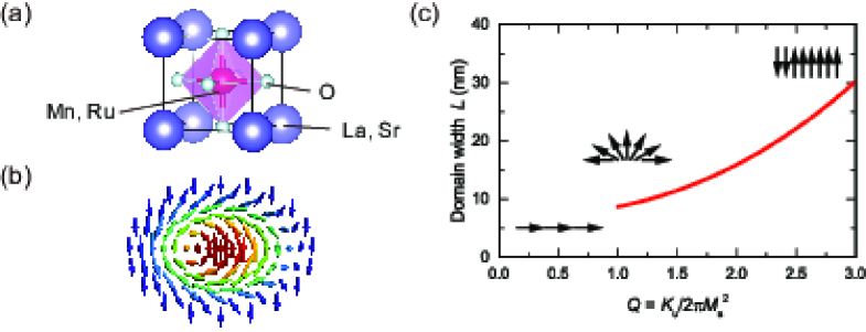
When a spin-polarized conduction electron passes through a non-collinear local spin order, non-trivial electromagnetic coupling emerges, as typified by the topological Hall effect (THE) observed in the compounds hosting magnetic skyrmion Bruno2004 ; Binz2008 . This Hall effect originates from the Berry phase acquired by the conduction electron whose spin is aligned to the local spin by the Hund’s-rule coupling. The half-metallic manganite is an attractive system to examine the THE because its magnitude is proportional to the spin polarization. The magnetic skyrmion is a particle-like object with a whirling spin texture as illustrated in Fig. 1(b). The exact definition of the magnetic skyrmion is a solitonic state stabilized by a competition between the exchange interaction enforcing a parallel spin alignment and the Dzyaloshinskii-Moriya interaction (DMI) twisting the parallel spin alignment. Hence, it is observed in noncentrosymmetric magnets (chiral skyrmion) Bogdanov1994 ; Resler2006 ; Muhlbauer2009 ; Yu2010 . Similar but slightly different particle-like magnetic texture is observed in centrosymmetric magnets known as the magnetic bubble which is stabilized by the magnetic dipolar interaction instead of DMI Malozemoff ; Hubert . Although the chiral skyrmion and magnetic bubble are different in the magnetization profile in the core region Kiselev2011 , their dynamical response and THE can be quantified by a common topological invariant called the skyrmion number (), which is defined as a number of spheres wrapped by the constituent spins Moutafis2009 ; Buttner2015 ; Nagaosa2013 . Hence, a magnetic bubble can be also regarded as a skyrmion in a broad sense, and is called ‘skyrmionic bubble’. Although the study on the skyrmionic bubble has a long history, it attracts recently a renewed interest , in particular, due to the richer skyrmion textures which are brought about by the underlying helicity degree of freedom Nagaosa2013 ; Ezawa2010 . Furthermore, the skyrmionic bubbles can form only in single-phase bulk crystals Nagai2012 ; Nagao2013 ; Yu2013 ; Morikawa2015 ; Kotani2016 ; Yu2012 ; Wang2016 , but also in thin film multilayers, sometimes in conjunction with DMI Finazzi2013 ; Li2014 ; Jiang2015 ; Gilbert2015 ; Woo2016 ; Lee2016 ; Soumyanarayanan2016 . The wide variety of materials choice is a major advantage of the skyrmionic bubble from the application point of view.
Although there are several reports on the observation of skyrmionic bubbles in bulk crystals of manganites Nagai2012 ; Nagao2013 ; Yu2013 ; Morikawa2015 ; Kotani2016 , neither the control of the skyrmion size nor the observation of THE has been achieved yet. Thin film structure provides an excellent platform for such a study. The size of the skyrmionic bubble in a thin film crucially depends on the magnitude of the uniaxial magnetic anisotropy. The quality factor , where is the uniaxial magnetic anisotropy energy and ( is saturation magnetization) is the dipolar interaction energy, is known to be a good measure of the domain size Yafet1988 ; Vedmedenko2000 . The domain size can be formed only when , and the domain width () becomes larger with as shown in Fig. 1(c). is calculated based on the following analytical solution,
| (1) |
where the film has layers (, is the film thickness and the lattice constant), the exchange interaction energy, , and Wu2004 ; Won2005 . The dependence of the domain width shown in Fig. 1(c) is estimated using 2.5 meV Moussa2007 , = 75 ( = 30 nm) and = 2.5 /f.u.. In this study, we tune the value in thin films of manganite by controlling using both the single-ion anisotropy induced by Ru doping and the epitaxial strain. We find that large THE appears when the perpendicular magnetic anisotropy and dipolar interaction are in keen competition.
II Sample Preparation
Thin films of La0.7Sr0.3Mn1-yRuyO3 (LSMRO) with a thickness of 30 nm were grown on (001) surface of (LaAlO3)0.3(SrAl0.5Ta0.5O3)0.7 (LSAT) substrates by a pulsed laser deposition technique. The Ru concentration was varied from 0 to 0.1. As reported in Ref. Yamada2005 , a too high growth temperature () or a low oxygen pressure () causes the deficiency of Ru. We optimized the growth condition at = 720 ∘C and = 40 mTorr to obtain thin films with a stoichiometric composition and an atomically flat surface. We verified by x-ray diffraction measurements that the films grown under the optimum condition have pseudomorphic structures with their -axis being elongated due to the compressive strain imposed by LSAT substrate whose lattice constant is smaller than that of LSMRO Sahu2000 .
III Magnetic and Transport Properties
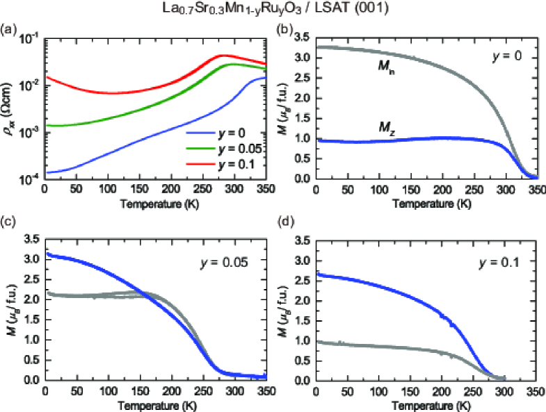
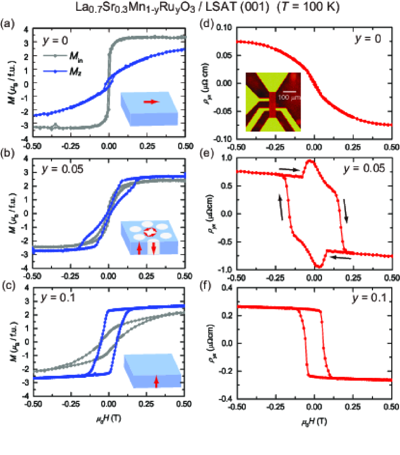
Figure 2 displays temperature dependence of the resistivity and magnetization for the films with = 0, 0.05, and 0.1. All films show a metallic behavior concomitant with the appearance of the ferromagnetic state, whereas the magnetic easy axis changes its direction. At = 0, the magnetic easy axis lies along the in-plane direction (). As increasing the Ru concentration, decreases and alternatively out-of-plane component () increases. and are comparable at , and dominates . The switching of the magnetic easy axis with Ru concentration is also apparent in the magnetic-field dependence of the magnetization shown in Figs. 3(a), (b), and (c). We thus that the film with is in a state of , the ideal condition for the generation of small skyrmions. To confirm the effect of the epitaxial strain on the magnetic anisotropy, we fabricated a thin film with = 0.05 on a SrTiO3 (STO) substrate to apply a tensile strain. As shown in Fig. 4, the - curve of the film grown on STO substrate indicates a robust in-plane magnetic anisotropy with a large coercive magnetic field, being consistent with the result in Ref. Yamada2005 .
It has been known that the magnetic anisotropy in manganite films can be controlled by the epitaxial strain Kwon1997 ; Wu1999 ; Dho2003 . However, the realization of a perpendicularly magnetized state only by the epitaxial strain requires a sizable compressive strain imposed by a largely lattice-mismatched substrate. This, however, causes a partial strain relaxation and homogeneous magnetic state. Furthermore, it is difficult to realize continuous variation of the magnetic anisotropy due to the limited choice of the substrates. Therefore, there has been no report on the dense and small skyrmion formation in manganite films. Our results indicate that the combination of the compressive strain and Ru doping enables the perpendicularly magnetized state by a modest strain and a continuous control of the magnetic anisotropy by changing Ru concentration. The compressive biaxial epitaxial strain imposed by LSAT substrate lifts the orbital degeneracy of the doped Ru4+ ion with orbital being at the lowest energy. The restored orbital angular momentum in a heavy element Ru induces the large single-ion anisotropy necessary for the perpendicular magnetic anisotropy.
Figures 3(d)-(f) show the Hall resistivity () of these films in Figs. 3(d)-(f). We used photolithography and ion-milling to pattern the films in Hall-bar shapes (inset of Fig. 3(d)). The of the films with and 0.1 are almost proportional to . On the contrary, the film with = 0.05 shows a large contribution of an additional Hall signal in the small magnetic field region. In conventional magnets, the ordinary Hall resistivity () proportional to the magnetic field and the anomalous Hall resistivity () proportional to contribute to . In compounds hosting non-zero spin chirality such as skyrmion, another contribution to emerges, that is THE. Since the film with is located near the critical point of , the skyrmion density is expected to be enhanced compared to the other compositions. We thus consider that the additional Hall signal in this compound stems from THE.
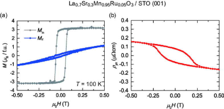
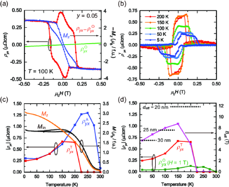
Figure 5(a) shows -dependence of , , and for the film with at 100 K. was derived from the linear fitting of measured at magnetic fields above 1 T where shows a linear dependence on . The contribution of is derived by fitting with ( is a constant) in outside of the hysteresis. The topological Hall resistivity () was derived by subtracting and from the total , i.e., Lee2009 ; Neubauer2009 ; Kanazawa2011 ; Huang2012 ; Porter2014 ; Yokouchi2014 . The derivation of was carried out by the same procedure at other temperatures, and traces are shown in Fig. 5(b). Figure 5(c) plots the peak value of as well as , , and as a function of temperature. appears at the ferromagnetic transition temperature ( K) and monotonously decreases with lowering temperature. By contrast, appears at 200 K which is apparently lower than , and has a peak at 150 K. The temperature dependence of is related to the variation of the magnetic anisotropy. The temperature dependence of the magnetization indicates that and becomes comparable at around 150 K, and () dominates above (below) this temperature. Above 150 K, is absent because the magnetic easy axis lies in-plane () and the skyrmion is not formed. As the system approaches the spin reorientation temperature, appears and reaches the maximum when state is realized. At this point, the skyrmion density is expected to be largest. At lower temperatures, the perpendicular magnetic anisotropy is further enhanced, which causes the increase of , leading to the reduction of the skyrmion density and accordingly the magnitude of .
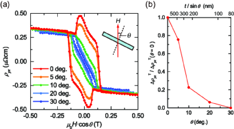
Additional evidence for the skyrmion formation in the film with is found in the dependence of the THE on the magnetic field direction Yokouchi2014 . Figure 6(a) shows that THE vanishes with increasing the tilt angle of the magnetic field (), whereas the anomalous Hall effect remains almost constant. The reduction of under inclined field is defined by , and is plotted as a function of in Fig. 6(b). reduces gradually, but it rapidly drops at around . The skyrmion diameter () is estimated as ( is the angle where THE disappears and is the film thickness) Ohuchi2015 . The top axis of Fig. 6(b) shows the scale of . It indicates that the typical value of is about 200-300 nm.
The size of skyrmion can be also estimated from the magnitude of THE. A single skyrmion gives an effective field of the magnetic flux quantum to a conduction electron, where is the Planck’s constant and is the elementary charge. Therefore, and the skyrmion density is related as Neubauer2009 , where is the ordinary Hall coefficient and is the spin polarization. in the metallic state of the perovskite manganites Park1998 . We derive the effective field () by comparing the temperature dependence of and shown in Fig. 5(d). The density of skyrmion estimated from is about 2000 at 100 K (1300 at 10 K), which means that the effective diameter of skyrmion () is 24 nm (30 nm) assuming a close-packed hexagonal lattice. This value is several times smaller than that estimated from the angle dependence of THE. We shall discuss the possible origins of this discrepancy later.
IV Real-Space Observations
We now describe the real-space observation of spin textures using magnetic-force microscopy (MFM) and Lorentz transmission electron microscopy (L-TEM). These two techniques offer complementary information on the spin texture; MFM is sensitive to the out-of-plane magnetization component, whereas L-TEM can detect the in-plane component Yu2010 ; Milde2013 ; Soumyanarayanan2016 . MFM observation was performed using an Attocube low-temperature atomic-force platform (AttoAFMI). During the scan, we detected the resonant frequency shift of the cantilever, which originates from the interaction between the magnetization of the tip and stray magnetic field from the film. The frequency shift is proportional to the second derivative of the local magnetic field with respect to direction. We employed a Nanosensors PPP-MFMR cantilever. The magnetization direction of the tip was defined by applying 5 T in direction at 10 K. Then, magnetic field was turned back to zero and MFM images were recorded at positive magnetic fields. We did not observe the magnetization reversal of the tip up to +300 mT. The excitation amplitude of the cantilever was 5 nm. Before the MFM observation, we recorded the surface topography and stored the tilt of the sample. Then, the MFM images were taken under constant height (100 nm) mode. It was not necessary to correct the MFM data by the topography signal because the sample is atomically flat.
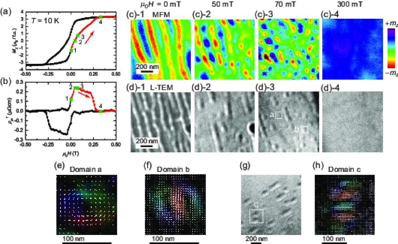
Figures 7(c) show the MFM images taken at four representative magnetic fields. The corresponding dependence of and are shown in Figs. 7(a) and 7(b). More detailed dependence of MFM image is displayed in Fig. 8. The MFM image at zero field shows a stripe domain (Fig. 7(c)-1). By applying a w, modulation patterns appear inside of the stripe domain as seen in the image at 50 mT (Fig. 7(c)-2). They are pinched off and become discrete domains as seen in the image at 70 mT (Fig. 7(c)-3). Near this magnetic field, reaches its maximum value. The domain structure finally disappears when exceeds the field value necessary to saturate as seen in the image at 300 mT (Fig. 7(c)-4), and accordingly, vanishes.
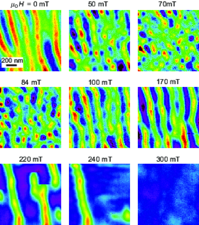
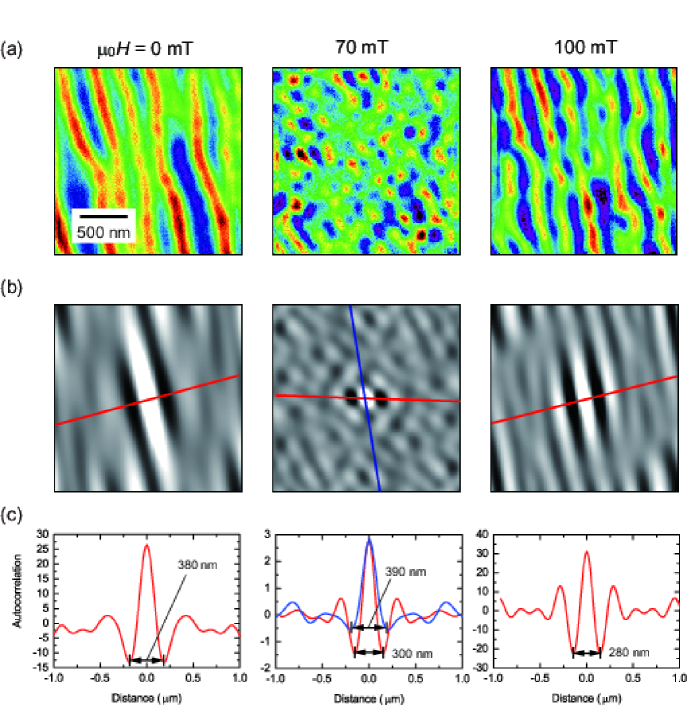
To clarify a possible existence of the periodic structure in the skyrmion phase as well as the stripe phase, the autocorrelation function analysis was performed for the MFM image at 70 mT as displayed in Fig. 9. Average distance between the adjacent skyrmions derived from the autocorrelation function is 300 nm (390 nm) along the red (blue) line (Fig. 9(c)). The skyrmion diameter estimated from the MFM image spread between 90 and 200 nm, and the average size is about 150 nm.
L-TEM observation was performed at the Lorentz TEM mode of a conventional transmission electron microscope (JEM-2100F (JEOL)). The sample for L-TEM observation was prepared by thinning the substrate of the film. The substrate was firstly thinned by mechanical polishing, and then, a part of the substrate was further thinned by Ar ion milling at a low temperature. Since the compressive epitaxial strain from LSAT substrate is important to induce the perpendicular magnetic anisotropy, the ion milling was stopped leaving the substrate thickness of about 200 nm. The magnetic field was controlled by changing the objective lens current. The magnetization textures were obtained by analyzing defocused L-TEM images with a software Qpt based on transport-of-intensity-equation (TIE) Ishizuka2005 .
The L-TEM images shown in Figs. 7(d) exhibit a similar evolution of the domain structure in the magnetic field as observed with MFM; stripe domain at zero field, isolated circular domain at 70 mT, and single domain state at 300 mT. The typical diameter of the isolated domain is about 100 nm. The size and density of magnetic textures observed by L-TEM are slightly different from those observed by MFM, probably caused by the partial strain relaxation in L-TEM sample which arose during the thinning process of the substrate. Another reason can be a different measurement temperature. The TIE analysis for a discrete domain denoted by domain-a in Fig. 7(d)-3 indicates that at the center the magnetic moments are pointing normal to the film surface and the outside moments have a swirling structure (Fig. 7(e)). This is a characteristic spin texture of the skyrmion with a skyrmion number . Furthermore, the TIE analysis for another discrete domain denoted by domain-b reveals a bound state of two skyrmions with opposite helicities, namely the biskyrmion state (Fig. 7(f)) Yu2013 ; Wang2016 , which has and therefore contributes doubly to the THE. We also found a domain in which four skyrmions are bound and possibly characterized by as shown in Figs. 7(g) and 7(h).
The diameter of skyrmion () observed by MFM and L-TEM is in the range of 100-200 nm, which is consistent with that estimated from the magnetic-field angle dependence of the THE, but estimated from the magnitude of THE is much smaller and is in the range of 20-30 nm. The fact of such discrepancy in skyrmion size indicates that THE is enhanced by several times by some reason. One apparent reason is the existence of skyrmions having multiple topological charges as revealed by the L-TEM images. Another possible reason is the THE in the momentum space as observed in frustrated and disordered ferromagnets Taguchi2001 ; Lyanda-Geller2001 . In the latter case, Hall effect is usually observed only near in perovskite manganites associated with thermally-driven hedgehog spin configuration Lyanda-Geller2001 . In our film with , the solid angle of the nearest-neighbor local moments can remain finite even at low temperatures due to a keen competition between the exchange and the dipolar interactions, which may induce the non-trivial Hall effect.
V Conclusions
In conclusion, we controlled the magnetic anisotropy in thin films of a half-metallic perovskite manganite. We found the emergence of large THE in the film with the perpendicular magnetic anisotropy being balanced with the magnetic dipolar interaction. MFM and L-TEM observations revealed the existence of a few hundreds nanometer sized skyrmion bubbles in the film. We find several times enhancement in the magnitude of THE compared with that expected from real-space observations, indicating a possibility of other mechanisms to enhance THE in perovskite manganites.
Acknowledgements.
We appreciate D. Shindo (Tohoku Univ. and RIKEN), T. Akashi (Hitachi Ltd.), and T. Tanigaki (Hitachi Ltd.) for their supporting in L-TEM observation. We also appreciate W. Koshibae (RIKEN) for fruitful discussions and D. Maryenko (RIKEN) for critical reading of our manuscript. This work was partially supported by PRESTO JST (JPMJPR16R5).References
- (1) Y. Tokura, Rep. Prog. Phys. 69, 797 (2006).
- (2) J.-H. Park, E. Vescovo, H.-J. Kim, C. Kwon, R. Ramesh, and T. Venkatesan, Nature(London) 392, 794 (1998).
- (3) S.-W. Cheong and M. Mostovoy, Nat. Mater. 6, 13 (2007).
- (4) Y. Tokura and S. Seki, Adv. Mater. 22, 1554 (2010).
- (5) P. Bruno, V. K. Dugaev, and M. Taillefumier, Phys. Rev. Lett. 93, 096806 (2004).
- (6) B. Binz and A. Vishwanath, Physica B 403, 1336 (2008).
- (7) A. Bogdanov and A. J. Hubert, J. Magn. Magn. Mater. 138, 255 (1994).
- (8) U. K. Rößler, A. N. Bogdanov, and C. Pfleiderer, Nature (London) 442, 797 (2006).
- (9) S. Mühlbauer, B. Binz, F. Jonietz, C. Pfleiderer, A. Rosch, A. Neubauer, R. Georgii, and P Böni, Science 323, 915 (2009).
- (10) X. Z. Yu, Y. Onose, N. Kanazawa, J. H. Park, J. H. Han, Y. Matsui, N. Nagaosa, and Y. Tokura, Nature (London) 465, 901 (2010).
- (11) A. P. Malozemoff, J. C. Slonczewski, and R. Wolfe, Magnetic domain walls in bubble materials. (Academic Press. 1979).
- (12) A. Hubert and R. Schäfer, Magnetic domains. (Springer 2000).
- (13) N. S. Kiselev, A. N. Bogdanov, R. Schäfer, and U. K. Rößler, Phys. Rev. Lett. 107, 179701 (2011).
- (14) C. Moutafis, S. Komineas, and J. A. C. Bland, Phys. Rev. B 79, 224429 (2009).
- (15) F. Büttner, et al., Nat. Phys. 11, 225 (2015).
- (16) N. Nagaosa and Y. Tokura, Nat. Nanotech. 8, 899 (2013).
- (17) M. Ezawa, Phys. Rev. Lett. 105, 197202 (2010).
- (18) T. Nagai, M. Nagao, K. Kurashima, T. Asaka, W. Zhang, and K. Kimoto, Appl. Phys. Lett. 101, 162401 (2012).
- (19) M. Nagao, Y.-G. So, H. Yoshida, M. Isobe, T. Hara, K. Ishizuka, and K. Kimoto, Nat. Nanotech. 8, 325 (2013).
- (20) X. Z. Yu, Y. Tokunaga, Y. Kaneko, W. Z. Zhang, K. Kimoto, Y. Matsui, Y. Taguchi, and Y. Tokura, Nat. Commun. 5, 3198 (2013).
- (21) D. Morikawa, X. Z. Yu, Y. Kaneko, Y. Tokunaga, T. Nagai, K. Kimoto, T. Arima, and Y. Tokura, Appl. Phys. Lett. 107, 212401 (2015).
- (22) A. Kotani, H. Nakajima, Y. Ishii, K. Harada, and S. Mori, AIP Advances 6, 056403 (2016).
- (23) X. Z. Yu, M. Mostovoy, Y. Tokunaga, W. Zhang, K. Kimoto, Y. Matsui, Y. Kaneko, N. Nagaosa, and Y. Tokura, Proc. Natl. Acad. Sci. USA 109, 8856 (2012).
- (24) W. Wang et al., Adv. Mater. 28, 6887 (2016).
- (25) M. Finazzi, M. Savoini, A. R. Khorsand, A. Tsukamoto, A. Itoh, L. Duò, A. Kirilyuk, Th. Rasing, and M. Ezawa, Phys. Rev. Lett. 110, 177205 (2013).
- (26) J. Li, K. W. Moon, A. Doran, M. A. Marcus, A. T. Young, E. Arenholz, S. Ma, R. F. Yang, C. Hwang, and Z. Q. Qiu, Nat. Commun. 5, 4704 (2014).
- (27) W. Jiang et al. Science 349, 283 (2015).
- (28) D. A. Gilbert, B. B. Maranville, A. L. Balk, B. J. Kirby, P. Fischer, D. T. Pierce, J. Unguris, J. A. Borchers, and K. Liu, Nat. Commun. 6, 8462 (2015).
- (29) S. Woo et al., Nat. Mater. 15, 501 (2016).
- (30) J. C. T. Lee et al., Appl. Phys. Lett. 109, 022402 (2016).
- (31) A. Soumyanarayanan et al., Nat. Mater. 16, 898 (2017).
- (32) Y. Yafet and E. M. Gyorgy, Phys. Rev. B 38, 9145 (1988).
- (33) E. Y. Vedmedenko, H. P. Oepen, A. Ghazali, J.-C. S. Lévy, J. Kirschner, Phys. Rev. Lett. 84, 5884 (2000).
- (34) Y. Z. Wu, C. Won, A. Scholl, A. Doran, H. W. Zhao, X. F. Jin, and Z. Q. Qiu, Phys. Rev. Lett. 93, 117205 (2004).
- (35) C. Won, Y. Z. Wu, J. Choi, W. Kim, A. Scholl, A. Doran, T. Owens, J. Wu, X. F. Jin, H. W. Zhao, and Z. Q. Qiu, Phys. Rev. B 71, 224429 (2005).
- (36) F. Moussa et al., Phy. Rev. B 76, 064403 (2007).
- (37) J. Choi, J. Wu, C. Won, Y. Z. Wu, A. Scholl, A. Doran, T. Owens, and Z. Q. Qiu, Phys. Rev. Lett. 98, 207205 (2007).
- (38) H. Yamada, M. Kawasaki, and Y. Tokura, Appl. Phys. Lett. 86, 192505 (2005).
- (39) R. K. Sahu and S. S. Manoharan, Appl. Phys. Lett. 77, 2382 (2000).
- (40) C. Kwon, M. C. Robson, K.-C. Kim, J. Y. Gu, S. E. Lofland, S. M. Bhagat, Z. Trajanovic, M. Rajeswari, T. Venkatesan, A. R. Kratz, R. D. Gomez, and R. Ramesh, J. Magn. Magn. Mater. 172, 229 (1997).
- (41) Y. Wu, Y. Suzuki, U. Rüdiger, J. Yu, A. D. Kent, T. K. Nath, and C. B. Eom, Appl. Phys. Lett. 75, 2295 (1999).
- (42) J. Dho, Y. N. Kim, Y. S. Hwang, J. C. Kim, and N. H. Hur, Appl. Phys. Lett. 82, 1434 (2003).
- (43) M. Lee, W. Kang, Y. Onose, Y. Tokura, and N. P. Ong, Phys. Rev. Lett. 102, 186601 (2009).
- (44) A. Neubauer, C. Pfleiderer, B. Binz, A. Rosch, R. Ritz, P. G. Niklowitz, and P. Böni, Phys. Rev. Lett. 102, 186602 (2009).
- (45) N. Kanazawa, Y. Onose, T. Arima, D. Okuyama, K. Ohoyama, S. Wakimoto, K. Kakurai, S. Ishiwata, and Y. Tokura, Phys. Rev. Lett. 106, 156603 (2011).
- (46) S. X. Huang, and C. L. Chien, Phys. Rev. Lett. 108, 267201 (2012).
- (47) N. A. Porter, J. C. Gartside, and C. H. Marrows, Phys. Rev. B 90, 024403 (2014).
- (48) T. Yokouchi, N. Kanazawa, A. Tsukazaki, Y. Kozuka, M. Kawasaki, M. Ichikawa, F. Kagawa, and Y. Tokura, Phys. Rev. B 89, 064416 (2014).
- (49) Y. Ohuchi, Y. Kozuka, M. Uchida, K. Ueno, A. Tsukazaki, and M. Kawasaki, Phys. Rev. B 91, 245115 (2015).
- (50) P. Milde, D. Köhler, J. Seidel, L. M. Eng, A. Bauer, A. Chacon, J. Kindervater, S. Mühlbauer, C. Pfleiderer, S. Buhrandt, C. Schütte, and A. Rosch, Science 340, 1076 (2013).
- (51) K. Ishizuka and B. Allman, J. Electron Microsc. 54, 191 (2005).
- (52) Y. Taguchi, Y. Oohara, H. Yoshizawa, N. Nagaosa, and Y. Tokura, Science 291, 2573 (2001).
- (53) Y. Lyanda-Geller, S. H. Chun, M. B. Salamon, P. M. Goldbart, P. D. Han, Y. Tomioka, A. Asamitsu, and Y. Tokura, Phys. Rev. B 63, 184426 (2001).