1School of Integrated Technology, Yonsei University,
Incheon, 21983, Korea (jaewon.yu@yonsei.ac.kr)
2Korea Research Institute of Ships and Ocean Engineering,
Daejeon, 34103, Korea (pwson@kriso.re.kr)
3Ship and Ocean Engineering Major, University of Science and Technology,
Daejeon, 34113, Korea
∗ Corresponding author
Empirical Modeling of Variance in Medium Frequency R-Mode Time-of-Arrival Measurements
Abstract
The R-Mode system, an advanced terrestrial integrated navigation system, is designed to address the vulnerabilities of global navigation satellite systems (GNSS) and explore the potential of a complementary navigation system. This study aims to enhance the accuracy of performance simulation for the medium frequency (MF) R-Mode system by modeling the variance of time-of-arrival (TOA) measurements based on actual data. Drawing inspiration from the method used to calculate the standard deviation of time-of-reception (TOR) measurements in Loran, we adapted and applied this approach to the MF R-Mode system. Data were collected from transmitters in Palmi and Chungju, South Korea, and the parameters for modeling the variance of TOA were estimated.
keywords:
Medium-frequency (MF) R-Mode system, time-of-arrival (TOA) measurements, variance modeling1 Introduction
The Global Navigation Satellite Systems (GNSS) [1, 2, 3, 4, 5, 6], which derive user positioning from signals received from satellites, such as the United States’ GPS [7] and Europe’s Galileo, are vulnerable to radio frequency interference (RFI) [8, 9, 10, 11, 12, 13] and ionospheric anomalies [14, 15, 16, 17, 18, 19, 20], primarily due to the long distance from satellites to the Earth’s surface, resulting in weakened signal strength. Instances of GNSS RFI have been reported globally, with notable cases in South Korea where North Korea has intentionally jammed GPS signals [21, 22, 23, 24, 25].
In response to these challenges, South Korea is developing an alternative navigation system called “R-Mode” for maritime users to use in the event of GNSS failure. The R-Mode system [26, 27, 28], a terrestrial integrated navigation system, processes eLoran [29, 30, 31, 32, 33, 34, 35, 36, 37] signals and other signals to calculate positions when GNSS signals are unavailable. The recent focus of R-Mode research is on methods utilizing medium frequency (MF) or very high frequency (VHF) signals for position calculation [38, 39, 40].
To support the deployment of the MF R-Mode system in South Korea, the development of a simulation tool capable of predicting the system’s navigation performance is necessary. The MF R-Mode simulation tool should be able to estimate signal strength and noise at a given location to calculate the signal-to-noise ratio (SNR). The variance of time-of-arrival (TOA) measurements is essential for estimating positioning accuracy. While a method to simulate the strength of the MF R-Mode signals has been proposed [41], a mathematical formula with appropriate parameters that relates the variance of TOA measurements to SNR for the MF R-Mode is not yet determined. In this study, we utilized the variance formula of the eLoran system but estimated parameters that are suitable for the Korean MF R-Mode testbed system based on actual MF R-Mode signal measurements.
2 Methodology
2.1 Variance Formula for eLoran TOR Measurements
In the eLoran system, the standard deviation of the bias-removed time-of-reception (TOR) measurements from a transmitter, denoted as , is a function of the transmitter’s jitter () and the signal-to-noise ratio () of the received signals, as illustrated by the following equation [42, 22]:
| (1) |
Here, represents the number of accumulated pulses of the Loran signal, determined by the group repetition interval (GRI) of the respective Loran chain. The number 337.5 was derived from a benchmark measurement [42].
Various factors can influence the transmitter jitter, such as thermal noise, bandwidth limitation, improper impedance termination, asymmetries in rise and fall times, and cross-coupling. It is essential to note that each transmitter has a different jitter value. Thus, the actual jitter should be estimated based on measurements [22].
2.2 Estimation of Parameters for the Variance Formula of MF R-Mode TOA Measurements
We drew inspiration from the conventional formula for calculating the standard deviation () of Loran’s TOR measurements and applied it to MF R-Mode. The modified formula for MF R-Mode, which calculates the variance of MF R-Mode TOA measurements, is as follows:
| (2) |
where represents the jitter of transmitter , is a constant, and is the signal-to-noise ratio of the received signals from transmitter .
We estimated and simultaneously based on actual MF R-Mode measurement data. The estimation method considered the point at which the residual sum of squares (RSS) between the actual measurements and the model curve was at its minimum. Minimizing RSS is a typical method in parameter estimation problems.
2.3 Data Acquisition and Processing for Parameter Estimation
In the data acquisition process, the “MFR-1a Medium Frequency R-Mode Receiver” by Serco was utilized to collect MF R-Mode signals from the transmitters in Palmi and Chungju, South Korea. This Serco receiver was also used in [43]. The Serco receiver provides raw phase measurements and SNRs of the received MF signals, which are pivotal in subsequent analyses.
The for transmitter in (2) is measured by the receiver, but in (2) is not directly measured. Thus, it is necessary to derive from the raw phase measurements . Since the measured values fall within the range of 0 and , they can exhibit sudden discontinuities due to measurement noise if is close to 0 or . In cases where there is a phase discontinuity larger than between two adjacent epochs, the phase value is adjusted by to ensure the continuity of phase values. This adjusted phase for transmitter is denoted as .
The relationship between for transmitter and is expressed as follows:
| (3) |
where represents the number of complete cycles of the MF continuous wave (CW) signal from the transmitter to the receiver, is the wavelength of the CW signal, and denotes the time-of-arrival or range for transmitter .
Given that the distance between transmitter and the stationary receiver remains constant, the variance of TOA, denoted as in (2), can be calculated as follows:
| (4) |
3 Results
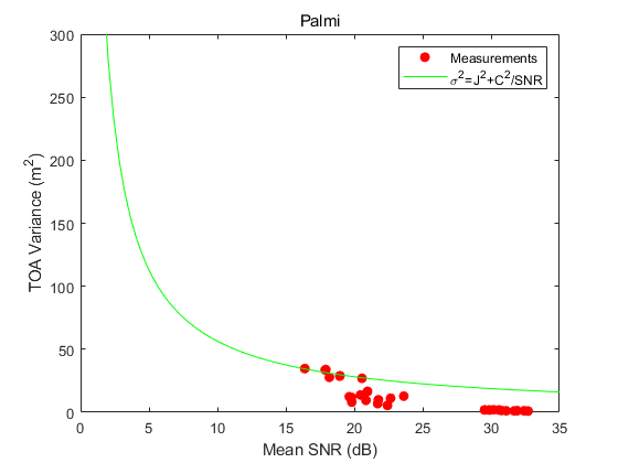
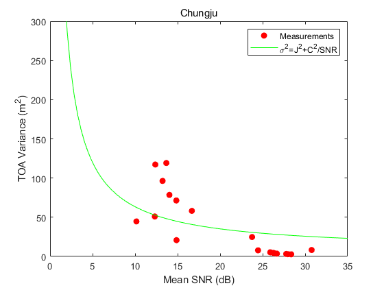
In Figs. 1 and 2, the red dots represent actual measurement values, with plotted along the x-axis and the variance of TOA (i.e., ) along the y-axis. The green curve corresponds to the model presented in (2), with the calculated values of and that yield the best fit by minimizing the RSS between the model and the measurements. Through this process, we determined that , , and achieved the minimum RSS. Using these determined values of and , can be predicted for a given using the relation presented in (2).
4 Conclusion
In this study, we estimated the parameters ( and ) of the variance model for MF R-Mode TOA based on actual measurements of and . The obtained variance model predicts realistic , which is necessary for positioning accuracy simulation. Therefore, this study contributes to improving the performance simulation capability for the MF R-Mode system under development in South Korea.
ACKNOWLEDGEMENT
This research was conducted as a part of the project titled “Development of integrated R-Mode navigation system [PMS4440]” funded by the Ministry of Oceans and Fisheries, Republic of Korea (20200450). This research was also supported by the Future Space Navigation and Satellite Research Center through the National Research Foundation of Korea (NRF) funded by the Ministry of Science and ICT, Republic of Korea (2022M1A3C2074404).
References
- [1] M. Kim, J. Seo, and J. Lee, “A comprehensive method for GNSS data quality determination to improve ionospheric data analysis,” Sensors, vol. 14, no. 8, pp. 14 971–14 993, Aug. 2014.
- [2] D. De Lorenzo, S. Lo, J. Seo, Y.-H. Chen, and P. Enge, “The WAAS/L5 signal for robust time transfer: Adaptive beamsteering antennas for satellite time synchronization,” in Proc. ION GNSS, 2010, pp. 2106–2116.
- [3] Y.-H. Chen, J.-C. Juang, D. De Lorenzo, J. Seo, S. Lo, P. Enge, and D. Akos, “Real-time dual-frequency (L1/L5) GPS/WAAS software receiver,” in Proc. ION GNSS, 2011, pp. 767–774.
- [4] Y. Lee, Y. Hwang, J. Y. Ahn, J. Seo, and B. Park, “Seamless accurate positioning in deep urban area based on mode switching between DGNSS and multipath mitigation positioning,” IEEE Trans. Intell. Transp. Syst., vol. 24, no. 6, pp. 5856–5870, Jun. 2023.
- [5] S. Kim and J. Seo, “Machine-learning-based classification of GPS signal reception conditions using a dual-polarized antenna in urban areas,” in Proc. IEEE/ION PLANS, Apr. 2023, pp. 113–118.
- [6] W. Kim and J. Seo, “Low-cost GNSS simulators with wireless clock synchronization for indoor positioning,” IEEE Access, vol. 11, pp. 55 861–55 874, 2023.
- [7] P. Misra and P. Enge, Global Positioning System: Signals, Measurements, and Performance. Ganga-Jamuna Press, 2011.
- [8] K. Park and J. Seo, “Single-antenna-based GPS antijamming method exploiting polarization diversity,” IEEE Trans. Aerosp. Electron. Syst., vol. 57, no. 2, pp. 919–934, Apr. 2021.
- [9] K. Park, D. Lee, and J. Seo, “Dual-polarized GPS antenna array algorithm to adaptively mitigate a large number of interference signals,” Aerosp. Sci. Technol., vol. 78, pp. 387–396, Jul. 2018.
- [10] S. Kim, K. Park, and J. Seo, “Mitigation of GPS chirp jammer using a transversal FIR filter and LMS algorithm,” in Proc. ITC-CSCC, 2019.
- [11] E. Schmidt, N. Gatsis, and D. Akopian, “A GPS spoofing detection and classification correlator-based technique using the LASSO,” IEEE Trans. Aerosp. Electron. Syst., vol. 56, no. 6, pp. 4224–4237, Dec. 2020.
- [12] K. Park, D. Lee, and J. Seo, “Adaptive signal processing method using a single-element dual-polarized antenna for GNSS interference mitigation,” in Proc. ION GNSS+, 2017, pp. 3888–3897.
- [13] S. Jeong, H. Lee, T. Kang, and J. Seo, “RSS-based LTE base station localization using single receiver in environment with unknown path-loss exponent,” in Proc. ICTC, 2020, pp. 958–961.
- [14] Y. Jiao and Y. T. Morton, “Comparison of the effect of high-latitude and equatorial ionospheric scintillation on GPS signals during the maximum of solar cycle 24,” Radio Sci., vol. 50, no. 9, pp. 886–903, 2015.
- [15] J. Lee, Y. Morton, J. Lee, H.-S. Moon, and J. Seo, “Monitoring and mitigation of ionospheric anomalies for GNSS-based safety critical systems,” IEEE Signal Process Mag., vol. 34, no. 5, pp. 96–110, Sep. 2017.
- [16] J. Seo, T. Walter, and P. Enge, “Availability impact on GPS aviation due to strong ionospheric scintillation,” IEEE Trans. Aerosp. Electron. Syst., vol. 47, no. 3, pp. 1963–1973, Jul. 2011.
- [17] H. Lee, S. Pullen, J. Lee, B. Park, M. Yoon, and J. Seo, “Optimal parameter inflation to enhance the availability of single-frequency GBAS for intelligent air transportation,” IEEE Trans. Intell. Transp. Syst., vol. 23, no. 10, pp. 17 801–17 808, Oct. 2022.
- [18] A. K. Sun, H. Chang, S. Pullen, H. Kil, J. Seo, Y. J. Morton, and J. Lee, “Markov chain-based stochastic modeling of deep signal fading: Availability assessment of dual-frequency GNSS-based aviation under ionospheric scintillation,” Space Weather, vol. 19, no. 9, pp. 1–19, Sep. 2021.
- [19] K. Sun, H. Chang, J. Lee, J. Seo, Y. Jade Morton, and S. Pullen, “Performance benefit from dual-frequency GNSS-based aviation applications under ionospheric scintillation: A new approach to fading process modeling,” in Proc. ION ITM, 2020, pp. 889–899.
- [20] N. Ahmed and J. Seo, “Statistical evaluation of the multi-frequency GPS ionospheric scintillation observation data,” in Proc. ICCAS, 2017, pp. 1792–1797.
- [21] W. Kim, P.-W. Son, S. G. Park, S. H. Park, and J. Seo, “First demonstration of the Korean eLoran accuracy in a narrow waterway using improved ASF maps,” IEEE Trans. Aerosp. Electron. Syst., vol. 58, no. 2, pp. 1492–1496, Apr. 2022.
- [22] J. H. Rhee, S. Kim, P.-W. Son, and J. Seo, “Enhanced accuracy simulator for a future Korean nationwide eLoran system,” IEEE Access, vol. 9, pp. 115 042–115 052, Aug. 2021.
- [23] P.-W. Son, J. Rhee, and J. Seo, “Novel multichain-based Loran positioning algorithm for resilient navigation,” IEEE Trans. Aerosp. Electron. Syst., vol. 54, no. 2, pp. 666–679, Oct. 2018.
- [24] P.-W. Son, J. Rhee, J. Hwang, and J. Seo, “Universal kriging for Loran ASF map generation,” IEEE Trans. Aerosp. Electron. Syst., vol. 55, no. 4, pp. 1828–1842, Oct. 2019.
- [25] P.-W. Son, S. G. Park, Y. Han, and K. Seo, “eLoran: Resilient positioning, navigation, and timing infrastructure in maritime areas,” IEEE Access, vol. 8, pp. 193 708–193 716, 2020.
- [26] P.-W. Son, Y. Han, K. Seo, and T. H. Fang, “Analysis of range measurement based on MF DGNSS infrastructures,” Journal of Positioning, Navigation, and Timing, vol. 11, no. 4, pp. 245–250, 2022.
- [27] S. Jeong and P.-W. Son, “Preliminary analysis of skywave effects on MF DGNSS R-Mode signals during daytime and nighttime,” in Proc. IEEE ICCE-Asia, 2022.
- [28] P.-W. Son, J. Park, J. Yu, S. Jeong, Y. Han, and T. H. Fang, “Skywave detection and mitigation for the MF R-Mode continuously operating reference station,” Sensors, vol. 23, no. 11, pp. 1–14, 2023.
- [29] P.-W. Son, S. G. Park, Y. Han, K. Seo, and T. H. Fang, “Demonstration of the feasibility of the Korean eLoran system as a resilient PNT in a testbed,” Remote Sens., vol. 15, no. 14, pp. 1–12, 2023.
- [30] P.-W. Son, J. Rhee, Y. Han, K. Seo, and J. Seo, “Preliminary study of multichain-based Loran positioning accuracy for a dynamic user in South Korea,” in Proc. IEEE/ION PLANS, 2018, pp. 1034–1038.
- [31] P. Williams and C. Hargreaves, “UK eLoran—initial operational capability at the port of Dover,” in Proc. ION ITM, 2013, pp. 392–402.
- [32] W. J. Pelgrum, “New potential of low-frequency radio navigation in the 21st century,” Ph.D. dissertation, Delft University of Technology, The Netherlands, Nov. 2006.
- [33] Y. Li, Y. Hua, B. Yan, and W. Guo, “Research on the eLoran differential timing method,” Sensors, vol. 20, no. 22, p. 6518, 2020.
- [34] W. Kim, P.-W. Son, J. Rhee, and J. Seo, “Development of record and management software for GPS/Loran measurements,” in Proc. ICCAS, 2020, pp. 796–799.
- [35] J. Park, P.-W. Son, W. Kim, J. Rhee, and J. Seo, “Effect of outlier removal from temporal ASF corrections on multichain Loran positioning accuracy,” in Proc. ICCAS, 2020, pp. 824–826.
- [36] J. Hwang, P.-W. Son, and J. Seo, “TDOA-based ASF map generation to increase Loran positioning accuracy in Korea,” in Proc. IEEE ICCE-Asia, 2018.
- [37] P.-W. Son, S. G. Park, K. Seo, S. Park, and T. H. Fang, “Preliminary study of the re-radiation effect of loran signal to improve the positioning accuracy,” in Proc. ENC, 2019, pp. 1–4.
- [38] G. Johnson and P. Swaszek, “Feasibility study of R-Mode combining MF DGNSS, AIS, and eLoran transmissions,” German Federal Waterways and Shipping Administration, Final Report, Tech. Rep., 2014.
- [39] ——, “Feasibility study of R-Mode using AIS transmissions: Investigation of possible methods to implement a precise GNSS independent timing signal for AIS transmissions,” German Federal Waterways and Shipping Administration, Final Report, Tech. Rep., 2014.
- [40] ——, “Feasibility study of R-Mode using MF DGPS transmissions,” German Federal Waterways and Shipping Administration, Final Report, Tech. Rep., 2014.
- [41] J. Yu and J. Rhee, “Simulation of medium-frequency R-Mode signal strength,” in Proc. IEEE ICCE-Asia, 2022.
- [42] S. C. Lo, B. B. Peterson, C. O. L. Boyce Jr., and P. K. Enge, “Loran coverage availability simulation tool,” in Proc. ION GNSS, Sep. 2008, pp. 2595–2605.
- [43] G. Johnson, K. Dykstra, S. Ordell, and P. Swaszek, “R-Mode positioning system demonstration,” in Proc. ION GNSS, 2020, pp. 839–855.