First in-beam studies of a Resistive-Plate WELL gaseous multiplier
Abstract
We present the results of the first in-beam studies of a medium size (1010 cm2) Resistive-Plate WELL (RPWELL):a single-sided THGEM coupled to a pad anode through a resistive layer of high bulk resistivity (10cm). The 6.2 mm thick (excluding readout electronics) single-stage detector was studied with 150 GeV muons and pions. Signals were recorded from 11 cm2 square copper pads with APV25-SRS readout electronics. The single-element detector was operated in at a gas gain of a few times 104, reaching 99 detection efficiency at average pad multiplicity of 1.2. Operation at particle fluxes up to 104 Hz/cm2 resulted in 23 gain drop leading to 5 efficiency loss. The striking feature was the discharge-free operation, also in intense pion beams. These results pave the way towards robust, efficient large-scale detectors for applications requiring economic solutions at moderate spatial and energy resolutions.
keywords:
Micropattern gaseous detectors; THGEM; Calorimetery; Gaseous detectors.1 Introduction
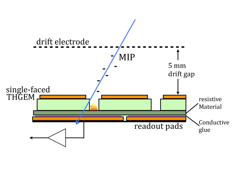
The Thick Gas Electron Multiplier (THGEM) was first introduced as a simple, robust detector suitable for applications requiring large detection areas [1]. Presently, THGEM-based detectors are being developed and employed in a large variety of basic and applied fields [2]. Examples are CsI-coated cascaded-THGEM UV-photon detectors [3, 4] for Ring Imaging Cherenkov (RICH) devices, advantageously replacing wire-chambers [5, 6, 7, 8, 9]; cryogenic gas-avalanche detectors [10] developed for charge readout in the vapor phase of noble liquid Time Projection Chambers (TPCs) for neutrino physics and rare-event searches [11, 12]; cryogenic gaseous photomultipliers (GPM) [13] for UV-photon detection in dark matter experiments, medical imaging [14] and neutron/gamma imaging in cargo inspection systems [15, 16]; fast-neutron detectors with dedicated converter-foils [17, 18]; and low-pressure helium-filled detectors for charged-particle track recording in an Active Target TPC [19]. Recent studies have also demonstrated the use of THGEMs immersed in liquid xenon as Liquid Hole Multipliers (LHM) [20, 21, 22] developed for recording both scintillation photons and ionization electrons in noble-liquid detectors, with possible applications in future dark matter and neutrino experiments. Lastly, thin THGEM-based sampling elements are under development by our group for potential application in digital hadronic calorimeters (DHCAL) in future linear-collider experiments [23, 24, 25]. The wide interest in THGEM-based detectors has resulted in the development of production techniques and concepts (for example [26, 27]), including the use of resistive films and materials for reducing the effects of occasional discharges [28, 29, 30]. In this context, the experience gained with various configurations of THGEM-based DHCAL sampling elements with resistive anodes [23, 31] has led to the development of a particularly promising candidate - the Resistive-Plate WELL (RPWELL) [32]. The RPWELL is a single-sided (i.e. copper-clad on one side only) THGEM electrode, coupled to a segmented readout anode (e.g. pads or strips) through a plate made of material of high bulk resistivity (figure 1). Extensive laboratory studies of the RPWELL [32] demonstrated discharge-free operation at high gas-avalanche gains and over a broad ionization range, making the RPWELL concept suitable for the detection of minimum- as well as highly ionizing particles. In [32] it was also shown that RPWELL detectors comprising resistive materials with a bulk resistivity of 109 cm do not suffer from a significant gain drop - and hence efficiency drop - under high particle flux. In this work we present the first results of RPWELL-detector evaluation with 150 GeV muon and pion beams, conducted at the CERN SPS/H4 RD51 beam-line. Compared to previously tested THGEM-based configurations [23, 24, 25], we show that this very thin (6.2 mm excluding readout electronics) single-stage detector configuration maintains discharge-free operation under muon beams, as well as under high-rate pion beams, while no degradation in the performance is observed. This robust discharge-free behavior in a single-stage - rather than cascaded - configuration, has a major advantage in terms of production costs, thus making the RPWELL highly promising for applications requiring large detection area such as DHCAL, where the instrumented area will be of the order of 4000-7000 m2 [33].
2 Experimental setup and methodology
2.1 The RPWELL detector
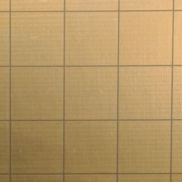
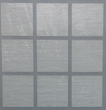
The THGEM electrode used in this work was 1010 cm2 in size, manufactured by 0.5 mm diameter hole-drilling in a 0.8 mm thick FR4 plate, copper-clad on one side only. The holes were arranged in a square lattice with a pitch of 0.96 mm; 0.1 mm wide rims were chemically etched around the holes. The hole-diameter, electrode thickness and rim width were chosen based on previous optimization studies [34]. Based on the results in [32], the single-sided electrode was coupled to an 88 matrix of 11 cm2 pads through a 1010 cm2 Semitron ESD225111http://www.quadrantplastics.com static dissipative plastic plate machined to a thickness of 0.4 mm. The bulk resistivity of this material was measured in [32] to be 2109 cm. Good electrical contact between the resistive plate and the readout pads is essential for efficient clearance of the avalanche electrons from the bottom of the resistive material. This was ensured as follows: the bottom side of the plastic was first painted uniformly with conductive silver paint (Demetron Leitsilber 200222http://www.tedpella.com/technote_html/16062_TN.pdf), then, a grid matching the readout pad structure was milled over its surface to avoid charge spread to neighboring pads. Each anode readout pad was glued with conductive epoxy (Circuit Works333https://www.chemtronics.com/descriptions/document/Cw2400tds.pdf) to the corresponding painted silver-pad on the resistive plate. Sections of the readout pad electrode and of the matching conductive pads painted on the resistive plate are shown in figure 2-a and 2-b respectively. On the basis of our previous experience with THGEM detector operation in neon mixtures, offering high attainable gas gain at relatively low operation potentials [35, 4], the detector was operated in , at a gas flow of 25-50 cc/min. At atmospheric pressure and room temperature, the most probable value (MPV) of the Landau distribution for cosmic muons corresponds to a total number of 14 ionization electrons along their track in the present 5 mm drift gap; this has been estimated in the laboratory from the ratio between the mean value of the peak of 55Fe x-rays and the MPV measured for cosmics, and is in accordance with the literature [36]. The electrodes were biased with individual HV power-supply CAEN A1833P and A1821N boards, remotely controlled with a CAEN SY2527 unit. The voltage and current in each channel were monitored and stored. All HV inputs were connected through low-pass filters. While the RPWELL bias with respect to the grounded anode (VRPWELL) was varied throughout the experiment, the drift voltage was kept constant (Vdrift= 250 V corresponding to a drift field of 0.5 kV/cm).
2.2 Trigger, tracking and DAQ system
The external trigger system used for event selection is described in [37]; it comprised three 1010 cm2 scintillators arranged in coincidence. The particle-tracking system, covering a total area of 66 cm2, comprised three MICROMEGAS detectors. The RPWELL chamber was placed between two tracker elements. The tracker signals, as well as those recorded from the 64 pads of the RPWELL detector were read out by an SRS readout system [38] equipped with a single Front-end Concentrator and front-end APV25 hybrids [39]. The SRS data acquisition was triggered by the scintillators coincidence signal. For each triggered event, the amplitude of the analog waveform (sampled in 20 bins of 25 ns each) in each channel was stored; this occurred only for signals crossing a threshold set by a zero-order suppression requirement, as described in section 2.3. The mmDAQ444Developed by M.Z.D. Byszewski (marcin.byszewski@cern.ch) online data acquisition software was used to store the synchronized data on a PC for further analysis.
The APV25 chip [40], originally designed for the silicon tracking detectors in CMS, has high rate capability and low noise. It was operated with a 75 ns shaping time. Due to the low noise level and high sensitivity of the chip, gas gains of the order of few times 103 are typically sufficient for efficient operation of the detector. As shown in [31, 32] the rise-time of a typical signal of single-sided THGEM detectors in a WELL configuration is 1-2 s. It comprises a fast component (up to 100 ns in ) and a slow one arising from the motion of avalanche ions inside the hole; the latter carries typically about 80 of the total amplitude. Since the APV25 was operated with 75 ns shaping time, less than 20 of the total induced signal was collected, requiring the operation of the detector with gas gains of the order of 104. In what follows we relate to the effective gain, which includes the effect of the short shaping time. This effective gain, estimated from the Landau MPV (section 2.1), is roughly an order of magnitude smaller than the gas gain.
2.3 Analysis framework
The analysis framework, including the noise suppression and the clustering algorithms are described in details in [25]. A common zero-order suppression factor (ZSF) sets the threshold of all APV25 channels. For each event the signal in an individual channel is stored only if the following condition is fulfilled:
Here S is the sum of the ADC counts in all of the nbins time bins after pedestal subtraction, and Pσ is the pedestal standard deviation.
The global detector efficiency was defined as the fraction of tracks matched to a cluster found not more than W [mm] away from the track trajectory in both x and y directions. The single-event multiplicity was defined as the number of pads in the matched cluster. The average pad multiplicity was defined as the average of the single-event multiplicity. A ZSF of 2 and cluster-track matching parameter W value of 15 mm were found optimal for both muons and pions. We emphasize that in the case of muons a value of W= 8 mm is sufficient for optimal performance. This point, as well as the optimization procedure are described in section 2.4. The detector’s discharge probability was defined as the number of discharges divided by the number of hits in the active region of the detector (i.e., in the total area covered by the crossing beam). The number of discharges was extracted directly from the power supply log files by counting the resulting spikes in the current monitor. The pion beam was narrower (a maximum area of 43 cm2) than both the acceptance of the scintillators and the tracker detectors. Therefore, the number of pion hits in the active region of the detector was estimated as the number of events where the three scintillators fired in coincidence. Due to the low rate of the muon beam, only pion runs were used to estimate the discharge probability. One should note that pions are prone to induce highly-ionizing secondary events; thus our study yielded an upper limit of MIP-induced discharge probability.
2.4 Working point: VRPWELL, threshold and matching parameter
The working point was adjusted to optimize the detector performance, targeting high detection efficiency at low average pad multiplicity. The latter is a requirement for particle counting, e.g. in a potential application of the RPWELL as a sampling element in Digital Hadron Calorimetry (DHCAL) [23]. The optimization was done in three steps using a set of measurements with 500 Hz/cm2 wide (55 cm2) muon beam and a 13000 Hz/cm2 narrow (22 cm2) pion beam. In both beams, only tracks hitting the detector in a 44 cm2 area around the beam center were considered.
Step 1: Choosing the nominal RPWELL operation voltage, VRPWELL -
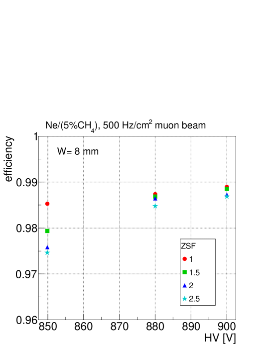
Figure 3 shows the global detector efficiency as a function of VRPWELL for different ZSF values measured in the muon beam. A constant matching parameter W= 8 mm was used. As can be seen in the figure, the global efficiency is already in a plateau at VRPWELL= 880 V for all ZSF values applied here. Hence VRPWELL= 880 V was selected as the nominal operation voltage. At the incoming particle fluxes used in this measurement, the effective gain (see section 2.2) at this operation voltage is 1700.
Step 2: Setting the nominal threshold (ZSF) -
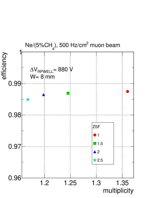
Operating at VRPWELL= 880 V, figure 4 shows the global detector efficiency as a function of the average pad multiplicity for different ZSF values measured in a muon beam. Targeting high detection efficiency at low average pad multiplicity, and since similar detection efficiency was recorded with all the ZSF values tested here, the threshold was set at ZSF= 2. Potential bias of the efficiency measurement due to noise hits was estimated in dedicated noise runs. In these runs the data was collected between spills using a clock as a random-like trigger. Processing this runs with a low threshold of ZSF= 0.7, the probability to measure a noise hit in an event was 10-4 which has a negligible effect on the efficiency even with large matching parameter.
Step 3: Fixing the nominal track-cluster matching parameter -
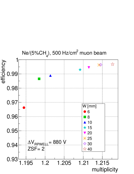
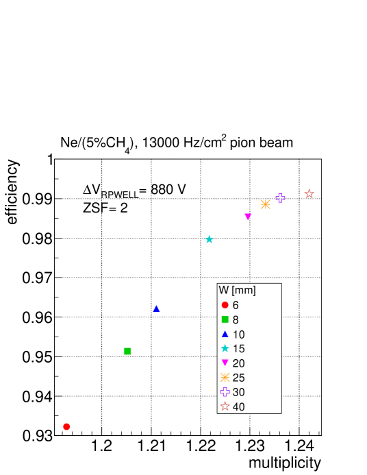
The global detection efficiency as a function of the average pad multiplicity is shown in figures 5-a and 5-b for different matching parameter values (W described in 2.3) as measured in muon and pion beams respectively. The detector was operated at the nominal voltage (VRPWELL= 880 V) and the analysis was performed with the nominal threshold (ZSF= 2) chosen above. Using the same matching parameter, lower efficiency is recorded in the pion beam compared to that measured with muons. As can be seen, at larger W values most of this apparent efficiency loss is restored and the detection efficiency reaches a plateau. This indicates that in the pion beam the cluster position is more often found farther away from the track position. This behavior could be explained by secondary particles originating from the incoming pion interactions, affecting the calculated cluster position. This interpretation is also supported by the slightly higher multiplicity recorded with pions compared to that with muons. Targeting high detection efficiency at low average pad multiplicity, the matching parameter was fixed at W= 15 mm for both muons and pions.
3 Results
3.1 Global and local detection efficiency and average pad multiplicity
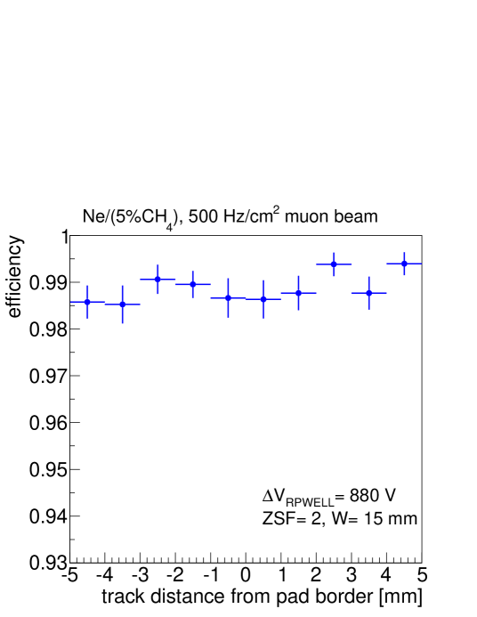
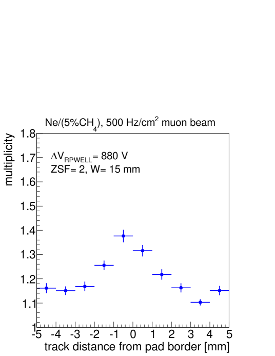
Under a low-rate (500 Hz/cm2) muon beam and nominal operation conditions, a global detection efficiency greater than 99 at an average pad multiplicity of 1.21 was recorded (figure 5-a). Under higher rate (13000 Hz/cm2) pion beam and the same nominal operation conditions, the performance of the detector was similar; a global detection efficiency greater than 98 at an average pad multiplicity of 1.23 (figure 5-b). In figure 6 the detection efficiency (figure 6-a) and the average pad multiplicity (figure 6-b) as a function of the distance from the pad boundaries along one axis on the detector plane are shown for operation with 500 Hz/cm2 muons. The detector was operated at the nominal operation conditions. While the local efficiency is uniform, higher multiplicity is seen to originate from muons traversing the detector close to the pad boundaries resulting in charge sharing between neighboring pads.
3.2 Performance under low and high incoming particle fluxes
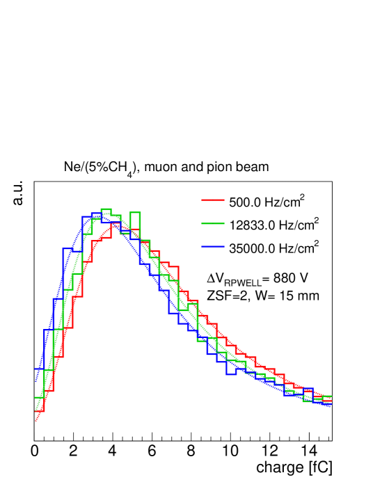
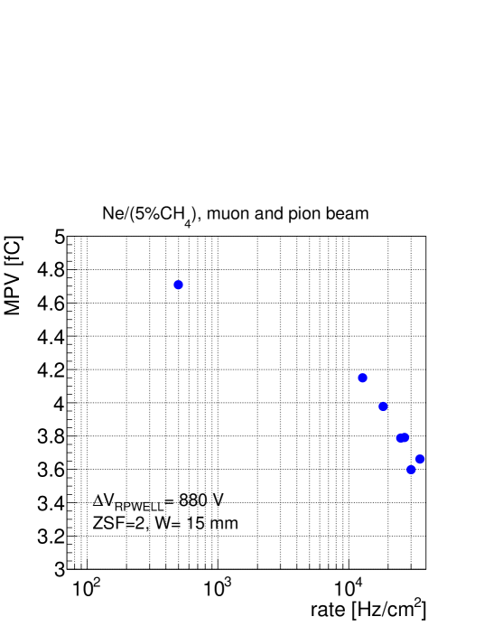
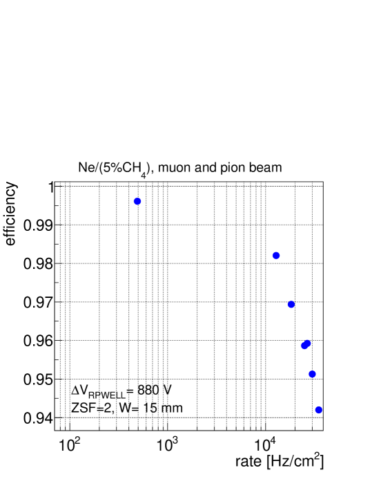
In [32], it was shown that the gain dependence on the counting rate was moderate for an RPWELL configuration similar to the one investigated here (0.6 mm thick ESD225 layer, bulk resistivity of 109 cm). A gain drop of 30 was observed at a counting rate spanning over 4 orders of magnitude. This study was repeated here with a 55 cm2 muon beam, with the lowest flux of 500 Hz/cm2, and with a narrow (23 to 43 cm2) pion beam, reaching 35000 Hz/cm2. The Landau spectra measured at three different incoming particle fluxes are shown in figure 7. The detector was operated at the nominal operation voltage, VRPWELL= 880 V. The spectra recorded at higher incoming particle flux are shifted towards lower charge values. The measured charge - estimated from the Landau MPV - is shown in figure 8-a as a function of the incoming particle flux. The global detection efficiency as a function of the incoming particle flux is shown, for the same set of measurements, in figure 8-b. A gain drop of 23 is noticeable over a counting-rate spanning over more than 2 orders of magnitude; this is in reasonable agreement with the gain drop reported in [32] at a similar gain for the same flux of soft x-rays. Over the same range of incoming particle flux, the global detection efficiency dropped by 5 from over 99 to 95 by increasing the flux from 500 Hz/cm2 to 35000 Hz/cm2 (figure 8-b). This drop in the detection efficiency could be avoided by setting the nominal operation voltage slightly higher than 880 V, still maintaining a discharge-free operation as shown in section 3.3 and 3.4.
3.3 Gain stability over time
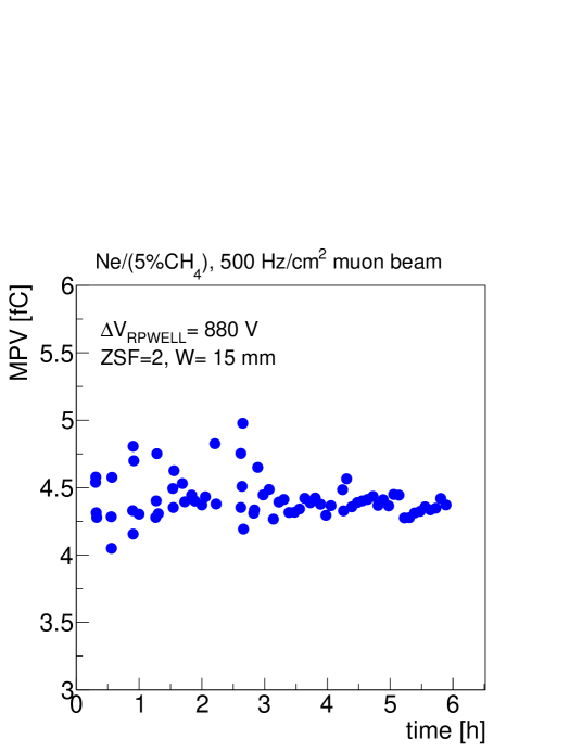
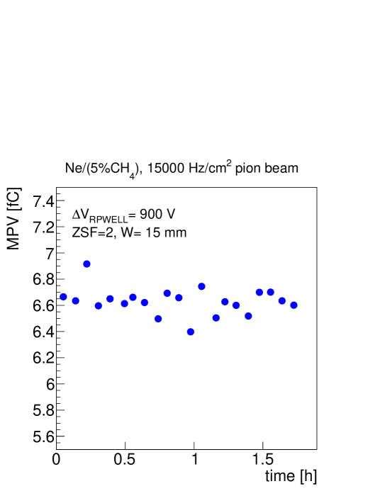
The detected charge as a function of time is shown in figure 9 for measurements carried out with low-rate (500 Hz/cm2) muons and high rate (15000 Hz/cm2) pions. The detector was operated under the nominal operation voltage with muons while with pions the voltage was increased to VRPWELL= 900 V (corresponding to an effective gain of 3000) to compensate for the slight gain drop with the high-rate pions (section 3.2). No significant gain variations were observed along the six hours of operation under the muon beam (figure 9-a) (RMS= 0.2 fC), and the two hours of operation under the pion beam (figure 9-b) (RMS= 0.1 fC). The measurement with muons showed a global detection efficiency of 99 at an average pad multiplicity of 1.2, while the pion beam showed a global efficiency of more than 98 at an average multiplicity of 1.25. As explained earlier, this small efficiency loss could be partially recovered selecting a higher matching parameter W, as also indicated by the slightly higher multiplicity.
3.4 Discharge probability
As mentioned in section 2.3, a discharge was defined as an abrupt increase in the current supplied to the detector. Due to the low rate of the muon beam, the discharge probability was measured with pions. As an example, during the 1.5 hours of measurement presented in figure 9-b, no current activity was recorded on any of the detector electrodes. At an incoming particle flux of 15000 Hz/cm2, this corresponds to discharge-free operation with over 108 pions resulting in a discharge probability of less than 10-8. It is worthwhile mentioning that under these conditions the detector had over 98 global detection efficiency. One should also note that pions are prone to induce highly-ionizing secondary events; thus this study yields an upper limit of discharge probability with MIPs. Similar behavior was recorded throughout longer periods, supporting the claim that the RPWELL is a discharge-free detector.
4 Summary and discussion
The results of a first in-beam study of an RPWELL detector with a Semitron ESD225 resistive plate were presented. This thin, single-stage detector was operated with at variable incoming muon and pion fluxes. High detection efficiency (greater than 99) at low average pad multiplicity (1.21) were demonstrated as well as stable operation over time. Discharge-free operation was recorded for the first time with a single-stage THGEM-based detector under pion flux as high as 15000 Hz/cm2 at a global detection efficiency greater than 98, maintained throughout the entire measurement. No electrical instabilities were observed over more than 108 pion events, resulting in recorded discharge probability lower than 10-8 in the hadronic beam.
These results could be compared to previous studies conducted with other THGEM-based detector configurations; single- and double-stage THGEM detectors operated with an induction gap [23] and single- and double-stage detectors based on the Segmented Resistive WELL concept [24, 25]. The RPWELL detector presents similar or better performance in terms of detection efficiency and pad multiplicity with the major advantage of being completely discharge free.
Compared to other technologies explored under similar conditions, the performance of the 1010 cm2 RPWELL detector reported in this work, with respect to detection efficiency and pad multiplicity, is better than that of 11 m2 RPCs [41, 42] and 3030 cm2 GEM detectors [43] and similar to that of 11 m2 MICROMEGAS [44, 45].
These results pave the way towards robust, efficient large-scale detectors for applications requiring economic solutions at moderate spatial and energy resolutions. For these purposes, other resistive materials as well as different gas mixtures may be considered.
Acknowledgements.
This research was supported in part by the I-CORE Program of the Planning and Budgeting Committee and The Nella and Leon Benoziyo Center for High Energy Physics. A. Breskin is the W.P. Reuther Professor of Research in the Peaceful use of Atomic Energy. F. D. Amaro acknowledges support by FCT under Post-Doctoral Grant SFRH/BPD/74775/2010.References
- [1] R. Chechik, A. Breskin, C. Shalem, D. Mörmann, Thick GEM-like hole multipliers: properties and possible applications,\hrefhttp://www.sciencedirect.com/science/article/pii/S0168900204016663 Nucl. Instr. Meth. A 535 (2004)
- [2] A. Breskin et al., A concise review on THGEM detectors, \hrefhttp://www.sciencedirect.com/science/article/pii/S0168900208012047 Nucl. Instr. Meth. A 598 (2009)
- [3] R. Chechik, A. Breskin and C. Shalem, Thick GEM-like multipliers-a simple solution for large area UV-RICH detectors,\hrefhttp://www.sciencedirect.com/science/article/pii/S0168900205015664 Nucl. Instr. Meth. A 553 (2005)
- [4] C.D.R. Azevedo et al., Towards THGEM UV-photon detectors for RICH: on single-photon detection efficiency in Ne/CH4 and Ne/CF4, \jinst52010P01002.
- [5] M. Alexeev et al., Development of THGEM-based photon detectors for Cherenkov Imaging Counters, \jinst52010P03009.
- [6] A. Breskin et al., CsI-THGEM gaseous photomultipliers for RICH and noble-liquid detectors,\hrefhttp://www.sciencedirect.com/science/article/pii/S0168900210022734 Nucl. Instr. Meth. A 639 (2011)
- [7] V. Peskov, M. Cortesi, R. Chechik and A. Breskin Further evaluation of a THGEM UV-photon detector for RICH-comparison with MWPC, \jinst52010P11004
- [8] M. Alexeev et al., Detection of single photons with ThickGEM-based counters, \jinst72012C02014
- [9] M. Alexeev et al., Status and progress of the novel photon detectors based on THGEM and hybrid MPGD architectures, \hrefhttp://www.sciencedirect.com/science/article/pii/S0168900214008730 Nucl. Instr. Meth. A 766 (2014)
- [10] A. Buzulutskov, Advances in Cryogenic Avalanche Detectors, \jinst72012C02025
- [11] F. Resnati et al., Stable operation with gain of a double phase Liquid Argon LEM-TPC with a 1 mm thick segmented LEM, \hrefhttp://iopscience.iop.org/article/10.1088/1742-6596/308/1/012016/meta J. Phys: Conf. Ser. 308-1 (2011)
- [12] A. Bondar et al., On the low-temperature performances of THGEM and THGEM/G-APD multipliers in gaseous and two-phase Xe1, \jinst62011P07008
- [13] L. Arazi et al., First results of a large-area cryogenic gaseous photomultiplier coupled to a dual-phase liquid xenon TPC, Accepted for publication in JINST; \hrefhttp://arxiv.org/abs/1508.00410 arXiv:1508.00410
- [14] S. Duval et al., On the operation of a micropattern gaseous UV-photomultiplier in liquid-Xenon, \jinst62011P04007
- [15] A. Breskin et al., A novel liquid-Xenon detector concept for combined fast-neutrons and gamma imaging and spectroscopy, \jinst72012C06008
- [16] I. Israelashvili, A comprehensive simulation study of a Liquid-Xe detector for contraband detection, \jinst102015P03030
- [17] M. Cortesi, R. Zboray, R. Adams, V. Dangendorf and H -M Prasser, Concept of a novel fast neutron imaging detector based on THGEM for fan-beam tomography applications, \jinst72012C02056
- [18] M. Cortesi et al., First studies of electron transport along small gas gaps of novel foil radiation converters for fast-neutron detectors, \jinst82013P01016
- [19] M. Cortesi, J. Yurkon and A. Stolz, Operation of a THGEM-based detector in low-pressure Helium, \jinst102015P02012
- [20] A. Breskin, Liquid Hole-Multipliers: A potential concept for large single-phase noble-liquid TPCs of rare events, \hrefhttp://iopscience.iop.org/article/10.1088/1742-6596/460/1/012020/meta J. Phys: Conf. Ser. 460 (2013)\hrefhttp://arxiv.org/abs/1303.4365 arXiv:1303.4365
- [21] L. Arazi et al., Liquid Hole Multipliers: bubble-assisted electroluminescence in liquid xenon, \jinst102015P08015
- [22] E. Erdal, L. Arazi, V. Chepel, M. L. Rappaport, D. Vartsky, A. Breskin, Direct observation of bubble-assisted electroluminescence in liquid xenon, Accepted for publication in JINST; \hrefhttp://arxiv.org/abs/1509.02354 arXiv:1509.02354
- [23] L. Arazi et al., THGEM-based detectors for sampling elements in DHCAL: laboratory and beam evaluation, \jinst72012C05011 \hrefhttp://arxiv.org/ftp/arxiv/papers/1112/1112.1915.pdf arXiv:1112.1915
- [24] L. Arazi et al., Beam Studies of the Segmented Resistive WELL: a Potential Thin Sampling Element for Digital Hadron Calorimetry, \hrefhttp://www.sciencedirect.com/science/article/pii/S0168900213011303 Nucl. Instr. Meth. A 732 (2013)
- [25] S. Bressler et al., Beam studies of novel THGEM-based potential sampling elements for Digital Hadron Calorimetry, \jinst82013P07017 \hrefhttp://arxiv.org/abs/1305.4657 arXiv:1305.4657
- [26] Q. Liu et al., A successful application of thinner-THGEMs, \jinst82013C11008
- [27] M. Alexeev et al., Ion backflow in thick GEM-based detectors of single photons, \jinst82013P01021
- [28] S. Bressler, L. Arazi, L. Moleri, M. Pitt, A. Rubin and A. Breskin, Recent advances with THGEM detectors, \jinst82013C12012
- [29] V. Peskov et al., Development and First Tests of GEM-Like Detectors With Resistive Electrodes, \hrefhttp://ieeexplore.ieee.org/xpl/abstractAuthors.jsp?arnumber=4346731tag=1 Nucl. IEEE Trans. Sci. 54 (2007)
- [30] G. Charpak, P. Benaben, P. Breuil, P. Martinengo, E. Nappi and V. Peskov, Progress in the development of a S-RETGEM-based detector for an early forest fire warning system, \jinst42009P12007
- [31] L. Arazi et al., Laboratory studies of THGEM-based WELL structures with resistive anodes, \jinst92014P04011.
- [32] A. Rubin, L. Arazi, S. Bressler, L. Moleri, M. Pitt and A. Breskin, First studies with the Resistive-Plate WELL gaseous multiplier, \jinst82013P11004. \hrefhttp://arxiv.org/abs/1308.6152 arXiv:1308.6152
- [33] J. Brau et al., \hrefhttp://www.linearcollider.org/ILC/Publications/Technical-Design-ReportThe international linear collider technical design report, (2013)
- [34] C. Shalem, R. Chechik, A. Breskin and K. Michaeli, Advances in Thick GEM-like gaseous electron multipliers - Part I: atmospheric pressure operation,\hrefhttp://www.sciencedirect.com/science/article/pii/S016890020502680X Nucl. Instr. Meth. A 558 (2006)
- [35] M. Cortesi et al., THGEM operation in Ne and Ne/CH4, \jinst42009P08001
- [36] F. Sauli, Principles of Operation of Multiwire Proportional and Drift Chambers, CERN 77-09 May (1977)
- [37] K. Karakostas, Micromegas telescope for the RD51 test beams, presented in the XXVIII Workshop on Recent Advances in Particles Physics and Cosmology, Thessaloniki Greece, 25-28 Mar 2010, \hrefhttp://hep2010.physics.auth.gr/Presentations/HEPXXVIII_Karakostas.pdfhttp://hep2010.physics.auth.gr
- [38] S. Martoiu, H. Muller, A. Tarazona and J. Toledo, Development of the scalable readout system for micro-pattern gas detectors and other applications, \jinst82013C03015
- [39] S. Martoiu, H. Muller, J. Toledo, Front-end electronics for the Scalable Readout System of RD51, in Proceedings of the Nuclear Science Symposium and Medical Imaging Conference (NSS/MIC), IEEE, Valencia Spain, 23-29 Oct 2011, \hrefhttp://ieeexplore.ieee.org/xpl/articleDetails.jsp?arnumber=6154414tag=1http://ieeexplore.ieee.org
- [40] M.J. French et al., Design and results from the APV25, a deep sub-micron CMOS front-end chip for the CMS tracker,\hrefhttp://www.sciencedirect.com/science/article/pii/S0168900201005897 Nucl. Instr. Meth. A 466 (2001)
- [41] B. Bilki et al., Calibration of a digital hadron calorimeter with muons, \jinst32008P05001
- [42] M. Affatigato et al., Measurements of the Rate Capability of Various Resistive Plate Chambers, Preprint; \hrefhttp://arxiv.org/abs/1507.06968 arXiv:1507.06968
- [43] J. Yu et al., Application of large scale GEM for digital Hadron calorimetry, Physics Procedia; \hrefhttp://www.sciencedirect.com/science/article/pii/S1875389212017063arXiv:1507.06968 37 (2012)
- [44] C. Adloff et al., MICROMEGAS chambers for hadronic calorimetry at a future linear collider, \jinst42009P11023
- [45] M. Chefdeville et al., Micromegas for sampling calorimetry, \hrefhttp://inspirehep.net/record/1360051/files/PoS(TIPP2014)054.pdfPoS (TIPP2014)054, (2014)