Geometric sliding mode control of mechanical systems on Lie groups
Abstract
This paper presents a generalization of conventional sliding mode control designs for systems in Euclidean spaces to fully-actuated simple mechanical systems whose configuration space is a Lie group for the trajectory-tracking problem. A generic kinematic control is first devised in the underlying Lie algebra, which enables the construction of a Lie group on the tangent bundle where the system state evolves. A sliding subgroup is then proposed on the tangent bundle with the desired sliding properties, and a control law is designed for the error dynamics trajectories to reach the sliding subgroup globally exponentially. Tracking control is then composed of the reaching law and sliding mode, and is applied for attitude tracking on the special orthogonal group and the unit sphere . Numerical simulations show the performance of the proposed geometric sliding-mode controller (GSMC) in contrast with two control schemes of the literature.
keywords:
Geometric control; Lie groups; Mechanical systems; Sliding subgroups.,
1 Introduction
Sliding mode control (SMC) (Utkin, 1977) has been proven to be a very powerful control design method for systems evolving in Euclidean spaces. Its design usually consists of two stages: the reaching stage where the controller drives the system trajectories to a sliding surface, a subspace embedded in the Euclidean space designed to convoy some specific characteristics (e.g., convergence time, actuator saturation) in accordance with the given control objectives, and a sliding stage where the system trajectories converge to the origin according to the reduced-order dynamics constrained in the sliding surface, achieving the control objectives. In the sliding stage, the reduced-order dynamics is independent of the system dynamics, and therefore, this control design method ensures its robustness against a certain class of disturbances and has achieved great success in a wide range of applications.
When this method is extended to mechanical systems whose configuration space is a general Lie group, care must be taken in the design of the sliding surface. Unlike the Euclidean case, when the system configuration space is a Lie group , its time rate of change belongs to the tangent space at the configuration . Therefore, the state space is composed of the tangent bundle . The topological structure and the underlying properties of the configuration space and the tangent space are very different. Without taking this into account in the SMC design, the sliding surface may not belong to the tangent bundle, and therefore no guarantee is offered to ensure that the system trajectories reach the sliding surface and the sliding mode may not exist at all (Gómez et al., 2019). The main problem is thus how to devise a group operation such that the tangent bundle is a Lie group and that the sliding subgroup is immersed in the tangent bundle so that the salient features of SMC in the Euclidean space mentioned above may be inherited by a general Lie group.
We present in this paper a general method of designing a sliding mode control, a geometric sliding mode control (GSMC), for fully-actuated mechanical systems whose configuration space is a Lie group. A generic kinematic control is first devised in the underlying Lie algebra (the tangent space at the group identity with a bilinear map), which enables us to build a Lie group on the tangent bundle where the system state evolves. Then a sliding subgroup is proposed on the tangent bundle, and the sliding mode is guaranteed to exist. The sliding subgroup is designed to convoy control objectives, in particular, the almost global asymptotic convergence of the trajectories of the reduced-order dynamics to the identity of the tangent bundle is considered, which is the strongest convergence that may be achieved by continuous time-invariant feedback in a smooth Lie group (Bhat & Bernstein, 2000). The reaching control law is then designed to drive the trajectories to the sliding subgroup globally exponentially. Tracking is then composed of the reaching law and sliding mode, as in the Euclidean case.
1.1 Related work
The geometric approach to control designs has achieved significant advances for mechanical systems on nonlinear manifolds, for recent developments in this topic, see, for instance, Bullo & Lewis (2005) and the references therein. As recognized in Koditschek (1989); Bullo et al. (1995); Maithripala et al. (2006), a key point in control design is how to define the tracking error. The tracking error defined on a Riemannian manifold relying on an error function and a transport map in Bullo & Murray (1999) may be simplified if the manifold is endowed with a Lie group structure (Maithripala et al., 2006), where the error notion can be globally defined explicitly and is easier to be manipulated for stability analysis of the closed-loop system (Maithripala & Berg, 2015; Saccon et al., 2013; De Marco et al., 2018; Lee, 2012; Sarlette et al., 2010). A similar situation is encountered in observer designs using an estimation error defined on a Riemannian manifold (Aghannan & Rouchon, 2003) versus an estimation error defined by the group operation on Lie groups bonnabel2009non. The ability to define a global error on Lie groups provides a powerful tool for treating the error as an object in the state space globally and controlling it as a physical system so that the tracking problem can be reduced to stabilizing the error dynamics to the group identity (Bullo et al., 1995; Maithripala et al., 2006; Spong & Bullo, 2005). Moreover, a separation principle can be proved in the geometric approach to control designs (Maithripala et al., 2006; Maithripala & Berg, 2015) when part of the state in the control law is estimated by an exponentially convergent observer designed on the Lie group (Bonnabel et al., 2009), similar to an LTI system. This opens a wide field of applications for systems on Lie groups, such as rigid body motion control and trajectory tracking in D and D spaces, given the significant advances in both geometric control designs (Bullo & Lewis, 2005; Spong & Bullo, 2005; Lee, 2011; Akhtar & Waslander, 2020; Rodríguez-Cortés & Velasco-Villa, 2022) and observer designs (Aghannan & Rouchon, 2003; Bonnabel et al., 2009; Mahony et al., 2008; Lageman et al., 2009; Zlotnik & Forbes, 2018).
GSMC on Lie groups has been considered using two main approaches: developing the SMC in the underlying Lie algebra or developing it on the Lie group itself. The main idea in the former approach is first expressing the tracking error defined on the Lie group in its Lie algebra through the locally diffeomorphic logarithmic map (Bullo et al., 1995). Since the Lie algebra is a vector space, a sliding surface can be designed as in the Euclidean case (Culbertson et al., 2021; Liang et al., 2021; Espíndola & Tang, 2022). In the latter approach, the sliding subgroup is designed directly on the Lie group. Since the topological structures of the configuration space (a Lie group) and the tangent space (a vector space) are very different when the underlying Lie group is not diffeomorphic to an Euclidean space, an important question arises as to how to ensure the sliding surface to be indeed a subgroup of the state space formed by the tangent bundle to guarantee the existence of the sliding mode and thus to inherit the salient features of SMC in the Euclidean space.
SMC designs using the second approach have been reported for Lie groups such as , for attitude control, and for motion controls (Ghasemi et al., 2020; Lopez & Slotine, 2021). However, the issue of whether the tangent bundle is a Lie group and whether the sliding subgroup is properly immersed on the tangent bundle was not addressed in these works. Therefore, the potential problem of lack of robustness due to the nonexistence of the sliding mode might appear. Recently, Gómez et al. (2019) brought this issue to the attention of the control community, and proposed an SMC on the rotation group with a sliding surface which was ensured to be a Lie subgroup immersed in the tangent bundle , and a finite-time convergent controller was devised for attitude control. This design method was applied in Meng et al. (2023) to design a second-order SMC for fault-tolerant control designs.
1.2 Contributions
We generalize the conventional sliding mode control designs for systems in Euclidean spaces to fully-actuated simple mechanical systems whose configuration space is a Lie group for the trajectory-tracking problem. The main contributions can be summarized as follows: (1) we endow the state space formed by the tangent bundle of the error dynamics with a Lie group structure by defining a group operation that is based on a generic kinematic control designed in the Lie algebra of the configuration Lie group; (2) we design a smooth sliding subgroup and show it to be a Lie subgroup of the tangent bundle, therefore, inheriting the Lie group structure of the state space; and (3) we design a coordinate-free geometric sliding mode controller for a fully-actuated mechanical system on a Lie group which drives the error dynamics to the sliding subgroup globally exponential at the reaching stage, the error dynamics then converges to the identity of the tangent bundle almost globally asymptotically at the sliding stage. In addition, rigid body tracking in D space is addressed on the special orthogonal groups and on the unit sphere , respectively, by applying the proposed geometric sliding mode control.
1.3 Organization
The rest of the paper is organized as follows. Section 2 presents the notation and background materials for simple mechanical systems with Lie groups as the configuration space. Section 3 first endows the state space formed by the tangent bundle with a Lie group structure under a group operation, which is defined based on a generic kinematic control law in the Lie algebra of the configuration space. Then, a smooth sliding subgroup is defined, which is a Lie subgroup immersed in the tangent bundle. The convergence to the identity of the tangent bundle of the reduced-order dynamics constrained on the sliding surface is analyzed based on Lyapunov stability. Section 4 gives the design of the GSMC, composed of a reaching law to the sliding subgroup and the convergence property of the sliding subgroup. Attitude tracking of a rigid body in D space is addressed in Section 5 respectively on the rotational group and the unit sphere , and simulation results under the GSMC developed on are presented in Section 6 for illustration and comparison. Conclusions are drawn in Section 7.
2 Mechanical systems on Lie groups
This section provides the notation and introduces the motion equations for a fully-actuated simple mechanical system on Lie groups. More details can be found in Bullo & Lewis (2005) and Abraham et al. (2012).
Given a finite-dimension Lie group , the identity of the group is denoted by . denotes the tangent space in the identity, which also defines its Lie algebra in the Lie bracket . Let and be the left and right translation maps, respectively, , and denote its corresponding tangent maps and , , it describes the natural isomorphism , which induces the equivalence for the tangent bundle . The inverse tangent map from to is denoted by , where , being a left-invariant vector field, with denoting the set of -sections of , and respectively for a right-invariant vector field , it follows that , and accordingly .
The cotangent space at is denoted by , while describes the dual space of the Lie algebra . Likewise, the cotangent bundle is denoted by . Given a -vector space , its dual space , and a bilinear map , the flat map is defined as , , , where denotes the image in of under the covector . If the flat map is invertible, then the inverse, known as the sharp map, is denoted by
The inner product on a smooth manifold is denoted by . A Riemannian metric on a Lie group assigns the inner product on each , . Moreover, when is left-invariant (resp. right-invariant), it induces an inner product in the Lie algebra by , . The kinetic energy is given by , where is the kinetic energy tensor, which induces a kinetic energy metric on . In the rotational motion of a rigid body, also represents the inertia tensor.
In the sequel, only the left invariance will be used. The proposed control methodology can be developed similarly for the right invariance. Also, subscripts and superscripts will be dropped when the meaning is clear. A left-invariant covariant derivative (affine connection) on a Lie group is denoted by for any vector fields . In addition, the Levi-Civita connection associated with the Riemannian metric is denoted by , which is unique and torsion-free. A left-invariant affine connection on a Lie group is uniquely determined by a bilinear map called the restriction of the left-invariant connection. In particular, the restriction for the left-invariant Levi-Civita connection is defined as
| (1) |
where the adjoint map is defined as , and is the dual map defined as . Furthermore, the adjoint action is , . So, the left-invariant Levi-Civita connection is explicitly expressed as
| (2) |
where , being the exponential map on , which is a local -diffeomorphism, and whose inverse is called the logarithmic map denoted by . By the left-invariance of vector fields , the covariant derivative (2) is expressed in terms of as follows
Consider a differentiable curve , where is the set of all intervals. Then a body velocity is defined as , for all , and therefore
| (3) |
A forced mechanical system is governed by the intrinsic Euler-Lagrange equations
| (4) |
where is the control force applied to the system on , being the control inputs, and the control forces. Furthermore, represents the vector field version of constraint forces, such as potential external forces, uncontrolled conservative plus dissipative forces, and unmodeled disturbances.
In view of (3) and the left-invariance of , the Levi-Civita connection in (4) can be explicitly expressed using (1)-(2) as
resulting in the controlled Euler-Poincaré equation
| (5) |
with , and .
The underlying mechanical system on the Lie group is then defined by the configuration Lie group , the inertia tensor , and the external forces .
3 Lie Group Structure of the State Space and the Sliding Subgroup
In this section, we will endow the tangent bundle with a Lie group structure by a properly designed group operation. For this purpose, an intrinsic control for kinematics is first proposed (3). Then we design a smooth sliding subgroup that is immersed in the tangent bundle so that it inherits the Lie group structure of the state space.
3.1 Intrinsic kinematic control
The purpose of this subsection is to design a control law for the kinematics (3) to render , the group identity. Let be an infinitely differentiable proper Morse function, which satisfies , , and . Morse functions, a class of error functions (Koditschek, 1989; Bullo et al., 1995), are guaranteed to exist on many Lie groups of practical interest considered in this paper (Maithripala & Berg, 2015; Bullo & Lewis, 2005). They represent potential energy that can be used to measure the distance between the configuration and the identity on . The following definition specifies the class of kinematic controls considered in the paper.
Definition 3.1 (Kinematic control law).
Let be a differentiable curve governed by (3), for all . A kinematic control law is a map that satisfies the following properties.
-
i.
,
-
ii.
,
-
iii.
, , where ,
-
iv.
, , where , and is a neighborhood of .
Some comments on the class of kinematic controls are in order. Properties (i)-(ii) are instrumental to building a particular Lie subgroup on the tangent bundle. Properties (iii)-(iv) represent the sliding (convergence) property of the reduced-order dynamics on the sliding subgroup (Lemma 5 below). In particular, Property (iii) states the almost-global asymptotic stability for system (3) in closed loop with the kinematic control law . Note that since is the set of closed-loop equilibria other than , they are critical points of . Since is a Morse function, the set consists of a finite number of isolated points. In addition, this set is nowhere dense, which means that it cannot separate the configuration space. Therefore, the complement is open and dense, i.e., is a submanifold of (Maithripala et al., 2006). Finally, Property (iv) establishes the local exponential stability of the closed-loop system, where the existence of the neighborhood is immediate because is a Morse function, which has a unique minimum at by definition.
Note that both and are of free design, provided that the properties in Definition 3.1 hold. However, it is worth considering the kinematic control law in the logarithmic coordinate, that is, , or some parallel vectors to (Akhtar & Waslander, 2020), as this map has been found to provide the strongest stability results, for example, almost global and local exponential convergence to the identity through a geodesic path (Bullo et al., 1995).
3.2 Lie Group structure for the state space
For systems described in (3) and (5), the state space is the tangent bundle . To endow it with a Lie group structure, we consider the binary operation defined in the following
| (6) |
, and .
Lemma 1 (The state space as a Lie group).
The tangent bundle endowed with the binary operation (3.2) is a Lie group, with
-
i.
Identity element: ,
-
ii.
Inverse element: , .
Being a smooth manifold with (3.2) a smooth operation, it only remains to verify the group axioms as follows.
- 1.
- 2.
-
3.
The associativity is proved straightforwardly by substitution, using the properties of Definition 3.1.
Remark 2 (Tangent bundle ).
The definition of the group operation (3.2) relying on the kinematic control in Definition 3.1 is crucial to define a sliding Lie subgroup immersed in in the next subsection. In fact, a group operation to endow to be a Lie group may simply be . However, this operation does not allow to design of a useful sliding subgroup, in particular, it fails to prove closure under the group operation, as will be seen below.
Remark 3 (Associativity).
The associativity proved in Lemma 1 ensures the proposed Lie group to be globalizable (Olver et al., 1996), that is, the local Lie group can be extended to be a global topological group. This fact allows us to develop a sliding mode control defined globally on the state space in contrast to the Lie groups defined locally in Gómez et al. (2019) and Meng et al. (2023).
3.3 Sliding Subgroup on
In this subsection, we define a smooth sliding subgroup on the tangent bundle. The following lemma shows that is an immersed submanifold of that inherits the topology and smooth structure of the tangent bundle (Lee, 2013).
Lemma 4 (Sliding Lie subgroup).
Define
| (7) |
where , the map is defined as
| (8) |
Then is a Lie subgroup under the group operation (3.2).
The smoothness of is immediate, because the map defined in (8) is smooth. The proof consists thus in showing that subset inherits the group structure of the Lie group , by verifying the following:
- i.
- ii.
-
iii.
Closure. Given , then and . By (3.2) . Thus, . That is, is closed under the group operation.
The following lemma shows that once a trajectory reaches the sliding subgroup it will stay on it and converges to the group identity.
Lemma 5 (Properties of the sliding subgroup ).
Consider the sliding Lie subgroup in (7). Then is forward invariant, i.e., for some . Moreover, almost globally asymptotically.
Consider a differentiable curve of the dynamics (3). Let be a proper Morse function with the unique minimum at . Then, along the trajectory and , it yields
Assume that , for some . Then gives . Therefore,
In light of Definition 3.1(iii), it follows that , for all , and , where is a nowhere-dense set with a finite number of points given in Definition 3.1(iii). Therefore, will remain on for all , and the equilibrium of (3) is almost globally asymptotically stable for all and locally exponentially stable , according to Definition 3.1(iv).
4 Geometric Sliding Mode Control (GSMC)
In this section, we design a control law, called the reaching law, for in the Euler-Poincaré equation (5) to drive the trajectory to the sliding subgroup . Then the tracking control objective will be achieved as a consequence of Lemma 5.
4.1 Reaching Law
The Euler-Lagrange dynamics (4), ignoring disturbance forces , is expressed as
| (9) |
which is defined on , being the state variable.
The intrinsic acceleration for the sliding variable (8) is calculated, by using (9), through the covariant derivative of with respect to itself as
Substituting the Euler-Poincaré equation (5) yields
| (10) |
where the skew-symmetry of the Lie bracket in (1) is used. The reaching law is then proposed as follows
| (11) |
with a design parameter.
Theorem 6 (Reaching Controller).
Consider the function defined below
| (12) |
Its time evolution along trajectories of (4.1) is given by
which in closed loop with the controller (11) yields
By Lemma 12 in Appendix A the term , for any . Therefore,
It follows from Proposition 6.26 of Bullo & Lewis (2005) that exponentially.
Remark 7 (Passivity of the Lagrangian dynamics).
Note that the first two right-hand terms of the control law (11) complete the terms . By exploring the intrinsic passivity properties in Lemma 12 in Appendix A, these terms were not canceled in the above stability analysis. This result was first given for the Lie group in Koditschek (1989). The lemma 12 extends this result to coordinate-free Lagrangian dynamics on a general Lie group, which has not been explored, to the authors’ knowledge, in the literature for stability analysis.
Remark 8 (The reaching controller ).
The reaching law (11) achieves the convergence of for the Euler-Lagrange dynamics (9), which implies that reaches the sliding subgroup exponentially. Note that the result of Theorem 6 holds when the external constraint forces can be compensated for by the controller , which was omitted from the control design. Otherwise, in the presence of bounded , will remain bounded and close to .
4.2 Tracking Control
Let be a twice differentiable configuration reference, with the corresponding reference body velocity given by . The problem is to design a control law to track the reference. The Lie group structure of the configuration space enables to define the following intrinsic configuration error
By left invariance the body velocity error is defined as
| (13) |
with . Then, the error dynamics evolving on is described by
| (14) |
being the state variable .
The tracking problem, therefore, boils down to stabilizing the identity on . By using the sliding-model control strategy, the error state is first driven to the sliding subgroup in the reaching stage, and then on the sliding subgroup, the reduced-order dynamics converges to the identity ensured by Lemma 5.
In terms of the error state the sliding variable (8) is given by
| (15) |
and, its covariant derivative, by using (1)-(2), is
Ignoring disturbance it follows from the Euler-Poincaré equation (5) that
| (16) | ||||
We proposed the following tracking controller
| (17) |
where is a design parameter. The following theorem establishes the stability of the equilibrium in the closed-loop system (16)-(4.2).
Theorem 9 (Tracking Controller).
Substituting the controller (4.2) in the error dynamics (16) yields the closed-loop dynamics
which has an equilibrium point at . The results follow as a consequence of Theorem 6 (the reaching stage) and Lemma 5 (the sliding mode).
Remark 10 (The tracking controller).
Theorem 9 gives a coordinate-free sliding mode control for a mechanical system whose configuration space is a general Lie group. The group structure allows defining globally a tracking error, whose dynamics evolves on the tangent bundle. The Lie subgroup of the sliding subgroup immersed on the tangent bundle ensures the existence of the sliding mode and thus inherits the salient features of the SMC in Euclidean spaces.
Similarly to the Euclidean case, the design of the sliding subgroup and the reaching law may incorporate other control objectives, such as finite-time convergence and controller saturation, which are, however, beyond the scope of the main purposes of this paper.
5 Attitude Tracking of a Rigid Body
In this section, we present the attitude tracking of a rigid body in the D space using the proposed GSMC. To illustrate the theoretic development, the problem is addressed using attitude representation by first the rotation matrix on and then by the unit quaternion .
5.1 GSMC for Attitude Tracking on
The group of rotations on is the Lie group , with the usual multiplication of matrices as the group operation. The identity of the group is the identity matrix of , and the inverse is the transpose for any . The Lie algebra is given by the set of skew-symmetric matrices , which is isomorphic to , i.e., . The Lie bracket in is defined by the cross product , . Denote the isomorphism , and respectively the inverse map . Then for a differentiable curve with left-invariant dynamics , the body angular velocity is given by
for all . The kinetic energy of the rotational motion of a rigid body is calculated as , where is the positive-definite inertia tensor. Therefore, , and . Hence, the rotational motion described by the Euler-Lagrange equation (4) is
| (18) |
The state evolves on the tangent bundle , and the control torque is expressed in the body frame. Furthermore, (18) is explicitly expressed, by using the Euler-Poincaré equation (5) and restriction (1), as
| (19) |
Let be a twice differentiable attitude reference, and , the reference angular velocity expressed in the body frame, which holds . Then, the intrinsic attitude error is
In view of (13) the (left-invariant) velocity error is
| (20) | ||||
Therefore, the distance between and is properly measured with the Morse function , proposed by Lee (2012). In fact, and is positive for all . Moreover, along the trajectories of (20), it satisfies
for all , where . Furthermore, given , for some arbitrarily small, verifies (Lee, 2012)
for all .
Consider the kinematic control law
| (21) | ||||
| (24) |
where , and is a matrix of size with zero-entries. It can verify readily Definition 3.1(i)-(ii) by (21). To verify Definition 3.1(iii)-(iv) under the kinematic control , consider the derivative of the Morse function along the error kinematics :
for all and for all , where
This proves that the kinematic control (21) also holds Definition 3.1(iii)-(iv).
Therefore, based on the kinematic control law (21) the following group operation is defined
| (25) | ||||
for any , . Thus, the tangent bundle is endowed with a Lie group structure with identity and inverse , . Likewise, given and in view of (15), the map
| (26) |
for some scalar , defines a Lie subgroup
| (27) |
under the group operation (25).
Thus, the tracking controller on is obtained from (4.2) and (26) as
| (28) |
where is a controller gain. Theorem 9 proves that controller (28) in closed loop with the system (19) renders the equilibrium point almost globally asymptotically stable for all , and exponentially stable for all .
Remark 11.
Note that in applying Theorem 9 it should define first a tracking error using the group operation on the configuration manifold, and then treat the error dynamics as a physical system. Otherwise, the sliding surface may not be a Lie subgroup. To see this more clear, consider , , then in the following tracking error may be defined by the group operation (25)
However, is not a sliding subgroup for the proposed Morse function .
5.2 Attitude Tracking on
The set of -vectors evolving on the unit sphere , with , , and , is a Lie group with identity , and inverse , under the group operation defined as
for any , . The Lie algebra is , which holds . Its Lie bracket operation corresponds to the cross product in . Thus, denote the isomorphism with the inverse map .
Rodriguez formula relates each antipodal point with a physical rotation of a rigid body, i.e., double covers the group . The adjoint action in is defined as , for any .
Given a differentiable curve with a left-invariant vector field , and a twice-differentiable reference configuration , , the body angular velocity and the reference angular velocity can be defined. We consider the following intrinsic tracking error and its left-invariant velocity error
| (29) | ||||
where is left invariant. Propose the Morse function , which satisfies , and . That is, function has a unique minimum critical zero at identity and is strictly positive for any other . Moreover, it verifies that
which suggests the following kinematic control law
| (30) |
for all . Indeed, when , it leads to
where for all , for some arbitrarily small. Consequently, the control law (30) satisfies all properties of Definition 3.1 for the Morse function .
The kinematic control law (30) enables the definition of the tangent bundle as a Lie group under the group operation
| (31) | ||||
, . Note that the identity is , and inverse, , . Therefore, the map
| (32) |
where , defines the sliding Lie subgroup
| (33) |
The attitude tracking controller on is thus defined as (4.2) using (29)-(32), which yields
| (34) |
By Theorem 9 controller (34) in closed loop with system (18) achieves the asymptotic convergence of for all , and exponential convergence when .
6 Simulations
To illustrate the theoretical results and for comparison, the proposed GSMC (28) was contrasted with two reported controllers: the ”linearization”-by-state-feedback-like (LSF) controller Eq. (26) of Maithripala et al. (2006), and the PD+ controller Eq. (23) of Lee (2012). For easy comparison, the applied torque control for each controller is rewritten in terms of
| (35) |
where is angular velocity error, is attitude error, and is the control gain.
The proposed GSMC law (28) is expressed as
| (36) | ||||
| (37) | ||||
Likewise, the LSF controller (26) of Maithripala et al. (2006) is given by
| (38) | ||||
| (39) | ||||
where and , for some . Finally, the PD+ controller (23) of Lee (2012) is rewritten as
| (40) | ||||
| (41) | ||||
The inertia tensor was given by
while the reference trajectory was calculated as (rad/s). Furthermore, the initial conditions were chosen as (rad/s), , where the expression is a rotation matrix described by the sequence 3-1-2 of Euler angles (Shuster et al., 1993), and the initial attitude was calculated as .
The simulations were carried out under three scenarios according to the distance between and the desired equilibrium , and to the undesired equilibrium measured by the Morse function used in Maithripala et al. (2006). Therefore, the initial attitudes , , and were assigned.
Finally, the design parameters for each controller were tuned in such a way that the energy-consumption level measured by in the first scenario is the same. The resulting controller gains were , for (36), , for (38), and , for (40). With these design parameters the control gain of (35) was for all .
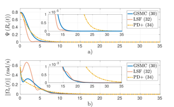
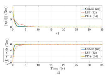
6.1 Scenario 1. Intermediate case.
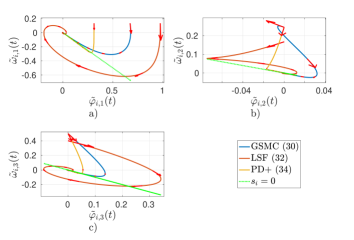
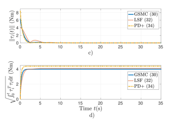
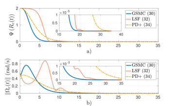
Figure 1 shows the performance of the controllers (36), (38), and (40) under the initial condition . Fig. 1(a) shows the attitude error , it is observed that the proposed controller (36) and controller (38) achieve the convergence in (s), while controller (40) achieves it in (s). Fig. 1(b) illustrates the norm for each controller, where the angular velocity error is calculated as (20), it can be seen that controller (40) takes (s) longer than the other controllers to reach . Furthermore, Figs. 1(c) and (d) draw the control effort and the energy consumption respectively, it is observed that, with the selected controller gains, all controllers consume the same amount of energy. Finally, Fig. 2 shows the behavior of the sliding variables (37), (39), and (41) compared to according to (35). It is observed that the proposed controller (36) allows convergence to complete the reach phase, while the LSF control scheme (38) presents an oscillatory behavior around the equilibrium point, in addition to the PD + controller (40) that follows closely until it reaches equilibrium.
6.2 Scenario 2. Starting close to the desired equilibrium point .
For this scenario, the initial condition was set to , which corresponds to an initial condition close to the desired equilibrium . Figs. 3(a) and (b) show that the controllers (36) and (38) reach the desired equilibrium at the same time (s), while the controller (40) takes (s) longer, which coincides with the previous scenario. However, as illustrated in Fig. 3(d), the proposed controller uses less energy than others to reach the desired equilibrium when the system starts close to the desired equilibrium.
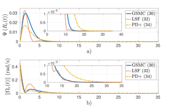
6.3 Scenario 3. Starting close to the undesired equilibrium point .
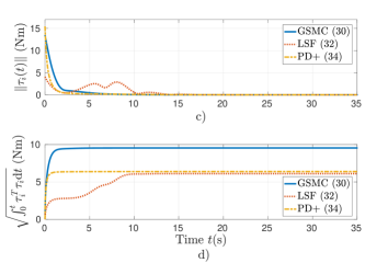
Figure 4 displays the performance of the controllers starting close to the undesired equilibrium point , i.e., . It is observed in Fig. 4(a) that the proposed controller (36) and the PD+ controller (36) present a delay of (s) before beginning the convergence of , however, the LSF controller (38) has the longest delay of (s). Notice that the proposed control scheme allows a faster convergence to the desired equilibrium point (Figs. 4(a) and (b)) at a cost of more energy consumption (Figs. 4(c) and (d)).
7 Conclusions
This paper presented a geometric sliding mode control for fully actuated mechanical systems evolving on Lie groups, generalizing the conventional sliding mode control in Euclidean spaces. It was shown that the sliding surface (a Lie subgroup) is immersed in the state space (a Lie group) of the system dynamics, and the tracking is achieved by first driving the trajectories of the system to the sliding subgroup and then converging to the group identity of the reduced dynamics restricted on the sliding subgroup, like sliding mode control designs for systems evolving on Euclidean spaces. An application of the result to attitude control was presented for the rotation group and the unit sphere . The simulation results illustrated the scheme and compared it with similar control designs in the literature.
References
- (1)
- Abraham et al. (2012) Abraham, R., Marsden, J. E. & Ratiu, T. (2012), Manifolds, tensor analysis, and applications, Vol. 75, Springer Science & Business Media.
- Aghannan & Rouchon (2003) Aghannan, N. & Rouchon, P. (2003), ‘An intrinsic observer for a class of lagrangian systems’, IEEE Transactions on Automatic Control 48(6), 936–945.
- Akhtar & Waslander (2020) Akhtar, A. & Waslander, S. L. (2020), ‘Controller class for rigid body tracking on so(3)’, IEEE Transactions on Automatic Control 66(5), 2234–2241.
- Bhat & Bernstein (2000) Bhat, S. P. & Bernstein, D. S. (2000), ‘A topological obstruction to continuous global stabilization of rotational motion and the unwinding phenomenon’, Systems & control letters 39(1), 63–70.
- Bonnabel et al. (2009) Bonnabel, S., Martin, P. & Rouchon, P. (2009), ‘Non-linear symmetry-preserving observers on lie groups’, IEEE Transactions on Automatic Control 54(7), 1709–1713.
- Bullo & Lewis (2005) Bullo, F. & Lewis, A. D. (2005), Geometric control of mechanical systems: modeling, analysis, and design for simple mechanical control systems, Vol. 49, Springer.
- Bullo & Murray (1999) Bullo, F. & Murray, R. M. (1999), ‘Tracking for fully actuated mechanical systems: a geometric framework’, Automatica 35(1), 17–34.
- Bullo et al. (1995) Bullo, F., Murray, R. M. & Sarti, A. (1995), ‘Control on the sphere and reduced attitude stabilization’, IFAC Proceedings Volumes 28(14), 495–501.
- Culbertson et al. (2021) Culbertson, P., Slotine, J.-J. & Schwager, M. (2021), ‘Decentralized adaptive control for collaborative manipulation of rigid bodies’, IEEE Transactions on Robotics 37(6), 1906–1920.
- De Marco et al. (2018) De Marco, S., Marconi, L., Mahony, R. & Hamel, T. (2018), ‘Output regulation for systems on matrix lie-groups’, Automatica 87, 8–16.
- Espíndola & Tang (2022) Espíndola, E. & Tang, Y. (2022), ‘A novel four-dof lagrangian approach to attitude tracking for rigid spacecraft’, (submitted to Automatica), available at arXiv preprint arXiv:2202.05227 .
- Ghasemi et al. (2020) Ghasemi, K., Ghaisari, J. & Abdollahi, F. (2020), ‘Robust formation control of multiagent systems on the lie group se (3)’, International Journal of Robust and Nonlinear Control 30(3), 966–998.
- Gómez et al. (2019) Gómez, C. G. C., Castanos, F. & Dávila, J. (2019), Sliding motions on so (3), sliding subgroups, in ‘2019 IEEE 58th Conference on Decision and Control (CDC)’, IEEE, pp. 6953–6958.
- Koditschek (1989) Koditschek, D. (1989), Autonomous mobile robots controlled by navigation functions, in ‘Proceedings. IEEE/RSJ International Workshop on Intelligent Robots and Systems’.(IROS’89)’The Autonomous Mobile Robots and Its Applications’, IEEE, pp. 639–645.
- Lageman et al. (2009) Lageman, C., Trumpf, J. & Mahony, R. (2009), ‘Gradient-like observers for invariant dynamics on a lie group’, IEEE Transactions on Automatic Control 55(2), 367–377.
- Lee (2013) Lee, J. M. (2013), Smooth manifolds, in ‘Introduction to smooth manifolds’, Springer, pp. 1–31.
- Lee (2011) Lee, T. (2011), Geometric tracking control of the attitude dynamics of a rigid body on so (3), in ‘Proceedings of the 2011 American Control Conference’, IEEE, pp. 1200–1205.
- Lee (2012) Lee, T. (2012), ‘Exponential stability of an attitude tracking control system on so (3) for large-angle rotational maneuvers’, Systems & Control Letters 61(1), 231–237.
- Liang et al. (2021) Liang, W., Chen, Z. & Yao, B. (2021), ‘Geometric adaptive robust hierarchical control for quadrotors with aerodynamic damping and complete inertia compensation’, IEEE Transactions on Industrial Electronics 69(12), 13213–13224.
- Lopez & Slotine (2021) Lopez, B. T. & Slotine, J.-J. E. (2021), Sliding on manifolds: Geometric attitude control with quaternions, in ‘2021 IEEE International Conference on Robotics and Automation (ICRA)’, IEEE, pp. 11140–11146.
- Mahony et al. (2008) Mahony, R., Hamel, T. & Pflimlin, J.-M. (2008), ‘Nonlinear complementary filters on the special orthogonal group’, IEEE Transactions on automatic control 53(5), 1203–1218.
- Maithripala & Berg (2015) Maithripala, D. S. & Berg, J. M. (2015), ‘An intrinsic pid controller for mechanical systems on lie groups’, Automatica 54, 189–200.
- Maithripala et al. (2006) Maithripala, D. S., Berg, J. M. & Dayawansa, W. P. (2006), ‘Almost-global tracking of simple mechanical systems on a general class of lie groups’, IEEE Transactions on Automatic Control 51(2), 216–225.
- Meng et al. (2023) Meng, Q., Yang, H. & Jiang, B. (2023), ‘Second-order sliding-mode on so (3) and fault-tolerant spacecraft attitude control’, Automatica 149, 110814.
- Olver et al. (1996) Olver, P. et al. (1996), ‘Non-associative local lie groups’, Journal of Lie theory 6, 23–52.
- Rodríguez-Cortés & Velasco-Villa (2022) Rodríguez-Cortés, H. & Velasco-Villa, M. (2022), ‘A new geometric trajectory tracking controller for the unicycle mobile robot’, Systems & Control Letters 168, 105360.
- Saccon et al. (2013) Saccon, A., Hauser, J. & Aguiar, A. P. (2013), ‘Optimal control on lie groups: The projection operator approach’, IEEE Transactions on Automatic Control 58(9), 2230–2245.
- Sarlette et al. (2010) Sarlette, A., Bonnabel, S. & Sepulchre, R. (2010), ‘Coordinated motion design on lie groups’, IEEE Transactions on Automatic Control 55(5), 1047–1058.
- Shuster et al. (1993) Shuster, M. D. et al. (1993), ‘A survey of attitude representations’, Navigation 8(9), 439–517.
- Spong & Bullo (2005) Spong, M. W. & Bullo, F. (2005), ‘Controlled symmetries and passive walking’, IEEE Transactions on Automatic Control 50(7), 1025–1031.
- Utkin (1977) Utkin, V. (1977), ‘Variable structure systems with sliding modes’, IEEE Transactions on Automatic control 22(2), 212–222.
- Zlotnik & Forbes (2018) Zlotnik, D. E. & Forbes, J. R. (2018), ‘Gradient-based observer for simultaneous localization and mapping’, IEEE Transactions on Automatic Control 63(12), 4338–4344.
Appendix A A passivity-like lemma
Lemma 12.
Given that the inner product on is a symmetric bilinear map, for any , it holds
because of the skew symmetry of the Lie bracket operation .