HAMMER: Heterogeneous, Multi-Robot Semantic Gaussian Splatting
Abstract
3D Gaussian Splatting offers expressive scene reconstruction, modeling a broad range of visual, geometric, and semantic information. However, efficient real-time map reconstruction with data streamed from multiple robots and devices remains a challenge. To that end, we propose HAMMER, a server-based collaborative Gaussian Splatting method that leverages widely available ROS communication infrastructure to generate 3D, metric-semantic maps from asynchronous robot data-streams with no prior knowledge of initial robot positions and varying on-device pose estimators. HAMMER consists of (i) a frame alignment module that transforms local SLAM poses and image data into a global frame and requires no prior relative pose knowledge, and (ii) an online module for training semantic 3DGS maps from streaming data. HAMMER handles mixed perception modes, adjusts automatically for variations in image pre-processing among different devices, and distills CLIP semantic codes into the 3D scene for open-vocabulary language queries. In our real-world experiments, HAMMER creates higher-fidelity maps (2x) compared to competing baselines and is useful for downstream tasks, such as semantic goal-conditioned navigation (e.g., “go to the couch”). Accompanying content available at hammer-project.github.io.
![[Uncaptioned image]](https://cdn.awesomepapers.org/papers/e011aa81-1be5-4eac-a4fd-d81509e28e04/abstract_hammer.png)
I Introduction
Mapping is a fundamental component in the autonomy stack. Recent advances in scene modeling with differentiable rendering [2, 3] have enabled robots to generate high-fidelity scene reconstructions in real time. Compared to traditional methods that use meshes, point clouds, or voxel grids to model physical features of the environment, these newer methods reason about the scene as a radiance field, represented as a parametric model regressed from photometric rendering losses. Radiance field-based methods can achieve photorealistic novel-view synthesis and even capture thin, transparent, and reflective surface geometries that are challenging to model with traditional representations. Furthermore, radiance fields can be augmented with additional information channels—like semantic embeddings from a pre-trained vision-language models—making them well-suited for language-driven robotics applications. In particular, 3D Gaussian Splatting [3] (3DGS) has been applied to a wide range of robot tasks including SLAM [4], safe teleoperation [5], manipulation [6], and navigation [7].
Multi-robot mapping is useful for rapidly exploring new environments, but when combined with traditional D reconstruction methods, can be difficult to scale efficiently, especially for teams of heterogeneous robots that have a mix of mobility and sensing capabilities. Alternatively, 3DGS is a promising representation for multi-robot mapping because of its scalability to large environments [8], modeling fidelity, and generalization to a broad range of sensing modalities including RGB, stereo depth, LiDAR [9], and semantics [10].
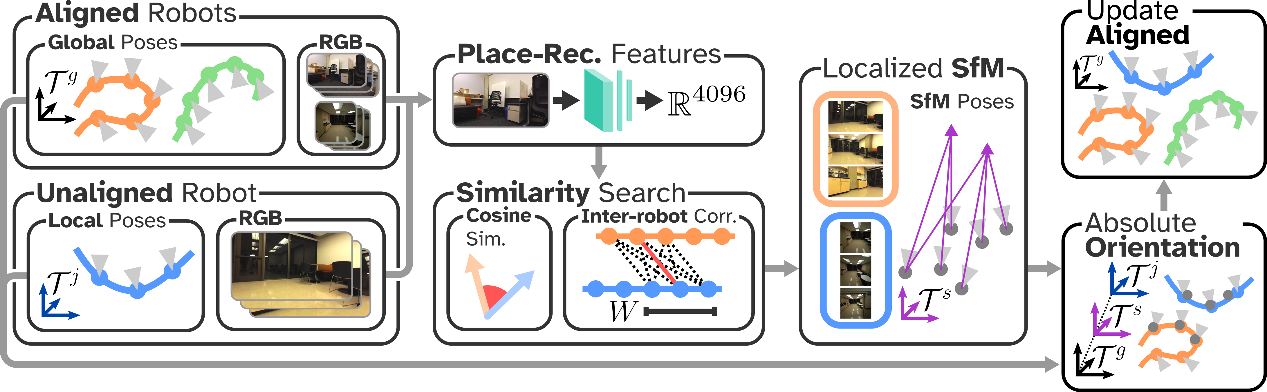
In this work, we propose HAMMER, Heterogeneous Asynchronous Multi-robot Mapping of Environmental Radiance. HAMMER enables a team of robots to collaboratively construct a 3DGS map of an unknown environment. Under HAMMER, robots broadcast color images and geometric sensing data, posed using the robot’s on-board localization system, to a mapping server. Semantic information is extracted from the images and the local poses of each robot are aligned to a global map frame. A semantic DGS map is trained online using the processed data streams from all robots. A server-based architecture incurs negligible requirements on on-board computational resources and can be deployed wherever typical communication infrastructure (e.g. WiFi/5G) is available. Importantly, HAMMER does not require any prior knowledge on the initial robot positions or inter-robot communication/observations, enabling asynchronous and ad-hoc robot deployments.
HAMMER is designed to generalize to a wide range of robots and devices, combining the advantages of each device into a single map. A shared map enables these robots to have more comprehensive spatial awareness compared to their own local maps. For example, drones can cover blind spots of mobile ground robots performing semantically-guided navigation. We intentionally propose a device-server architecture with a centralized 3DGS training module to ensure that HAMMER is real-time executable with existing robots and wearable devices. Computing requirements for 3DGS training are currently beyond the on-board compute capabilities of most robots and wearables. When on-board computing matches the power of current high-end GPUs, fully distributed algorithms [11] may become a compelling alternative.
We validate the performance of HAMMER on real-world streaming data from a heterogeneous team of egocentric human-wearable devices (Aria glasses [1]) and ground robots with a stereo camera. Furthermore, we demonstrate the practical effectiveness of HAMMER by simultaneously optimizing the DGS map and performing multi-robot trajectory optimization with open vocabulary, semantic goal specification. The contributions of HAMMER (Figure 1) are:
-
•
a robust and metric inter-robot frame alignment using RGB images to align coordinate systems across devices with different image sensors and SLAM algorithms,
-
•
and an online training scheme for DGS from heterogeneous, asynchronous devices.
We demonstrate HAMMER in hardware deployments with 3-4 devices across 2 real-world environments. HAMMER provides more than 40% better Mean-Squared-Error (MSE) compared to the Di-NeRF [12] baseline.
II Related Work
Radiance Fields and Gaussian Splatting. NeRFs, proposed in [2], use neural networks to model radiance fields from posed RGB images and demonstrate photorealistic novel view synthesis and high-fidelity geometric reconstruction by optimizing these networks using a photometric loss with a differentiable rendering process. Follow up works showed that more sophisticated ray-sampling methods [13] greatly improves reconstruction accuracy, and optimized model architectures [14] can reduce training times by orders of magnitude. However, NeRFs remain computationally expensive to optimize and query. As an implicit representation, NeRFs make it difficult to extract the underlying scene geometry. On the other hand, DGS [3] maintains many of the benefits of NeRFs and is significantly faster to optimize. The use of geometric primitives as a representation also facilitates collision quantification and contact modeling with the environment [7].
Online 3DGS Training and 3DGS-based SLAM. DGS is typically optimized using the following offline optimization scheme: (i) image capture using a high-resolution camera, (ii) image pose estimation using structure-from-motion (SfM) like COLMAP [15], and (iii) DGS map optimization on the static dataset. However, this processing and training scheme is not well suited for robotics tasks where data is incrementally received from onboard sensors and prevents the DGS map from being used during deployment. LEGS [10] proposes using an incrementally optimized semantic 3DGS map with camera poses initialized from an on-board SLAM system. Gaussian Splatting SLAM [4] and SplaTAM [16] go a step further, using DGS as the map representation for SLAM. While LEGS does discuss using multiple cameras, these cameras are on a fixed rigid frame, and does not constitute a multi-robot system.
Multi-robot Mapping. Mapping using multi-robot systems is a widely studied field, and many diverse methods have been proposed. Historically, multi-robot mapping and SLAM systems have utilized more traditional robot map representations like point clouds [17] and meshes [18]. Collaborative mapping is well-suited for scenarios requiring robust and rapid exploration [19].
MACIM [20] proposes a decentralized multi-robot mapping algorithm that optimizes a signed distance function, while other approaches use NeRFs [21, 12]. Of these works, only Di-NeRF [12] addresses the problem of frame alignment from the robots’ local frames to a global map frame, which it does through gradient-based optimization. MULAN-WC [22] proposes using inter-robot observations from wireless signal measurements to align robots for multi-robot NeRF training. In contrast, our work does online continual inter-robot frame alignment from multiple heterogeneous devices.
Developed concurrently to this work, MAGiC-SLAM [23] proposes a multi-robot DGS SLAM pipeline that enables robots that are running independent DGS SLAM instances to fuse their individual maps into a global map. The key differences when compared to HAMMER are that MAGiC-SLAM relies on the capability of individual devices to train local DGS maps, and that it does not account for heterogeneous sensing devices. There is no publicly available code for this method.
III Problem Setup
We consider a set of robots, indexed , deployed in a shared environment. Their deployments can be asynchronous, potentially lacking any temporal overlap between individual robot deployments. Each robot produces color images, geometric information (e.g. depth images or point clouds), and camera pose estimates in with respect to an arbitrary local coordinate frame . These estimates can be retrieved from on-board VIO or SLAM commonly available on commercial robots and devices. The robots continuously stream all data to a mapping server during deployment. The data is received incrementally by the server as the robot navigates through the environment. The goal is to continuously incorporate every robot’s data into the DGS map within a consistent global coordinate frame . We assume there is sufficient visual overlap within the data streams of the robots such that alignment is possible.
IV Method
We decompose the problem into (i) inter-robot alignment where the data from all robots is aligned to a common reference frame, and (ii) multi-robot DGS mapping where streaming data is incorporated into a DGS map.
IV-A Inter-robot Alignment
In HAMMER’s inter-robot alignment module (see Figure 1) we begin by selecting one of the contributing robots as the origin, and making its local reference frame the global frame, . This robot may be selected at random or simply as the first robot that connects to the server. The selected reference frame is assumed to be scaled to metric units. This origin robot immediately begins integrating its streamed data into the 3DGS map. Already connected, or newly connected, robots that are not the origin robot are designated as unaligned and stream their data to a cache that will be used to align the robots to the global frame and then aggregated into the 3DGS optimization data pool (see Section IV-B). The alignment module runs at fixed intervals—parallel to the mapping process—as new data is received from the unaligned robots.
IV-A1 Correspondences
In the first stage of the alignment process, HAMMER detects potential candidate correspondences between the data of the unaligned robots and that of the aligned robots. Regardless of alignment status, a place-recognition feature vector is extracted for every color image received from the collaborating robots using NETVLAD [24]. Additionally, the features from the unaligned robots are periodically compared to those of the aligned robots using cosine similarity. The similarities are thresholded with where indicates the index of the aligned and unaligned robot, respectively. For pairs of images with similarities exceeding , the alignment module performs an additional feature-matching verification step where SuperPoint local features [25] are extracted for each image, and then matched using LightGlue [26]. If the fraction of features matched during verification exceeds a fixed threshold (0.25 in our experiments) then the image pair is accepted as a potential inter-robot correspondence.
IV-A2 Adaptive Thresholding
When no image pairs pass the threshold, then is increased to match the mean of all place recognition similarities greater than the previous value. This thresholding scheme is used because multiple instances of the same camera (e.g. two robots with ZED cameras) tend to have higher similarity regardless of visual content, resulting in spurious matches. Dynamic thresholding allows initial values of to be set to a low value for all robot pairs, circumventing any hyper-parameter tuning that would otherwise be necessary. While this procedure for determining candidate alignment image pairs grows quadratically in the number of images per robot, many of these operations can be cached, forming a relatively small computational footprint.
IV-A3 Localized Structure-from-Motion
For every potential correspondence between an aligned and unaligned robot, a small set of color images within some fixed temporal window size is selected from each robot’s data cache on the server. Subsets of the pair’s data streams are used to perform localized SfM, as opposed to bulk SfM where the whole data stream is used. We use the COLMAP backend [15] with SuperPoint features and the SuperGlue matcher [27], which demonstrates robustness in aligning images from different device types. Importantly, the localized SfM does not use any pose information from the robot’s SLAM systems, producing an independent relative pose estimate between robots.
IV-A4 Registration
The output of the localized SfM procedure lies in an arbitrary coordinate frame, . The final stage of alignment determines the scaled transformation mapping poses from the local frame of the unaligned robot, , to the global frame of the aligned robot, . The relative scaled transform, rotation , translation , and scaling , transforms a pose in to through
| (1) |
where is the transformed pose. Scaled transformations account for non-metric localization software used by any robot and the SfM intermediary frame. So long as the origin frame is set using a robot with a metric localization system, the map will retain the metric scale.
Computing the relative transformation for unaligned robots requires solving two instances of a modified absolute orientation problem [28]. One instance computes the scaled transformation from the unaligned to the intermediary SfM frame . The second instance transforms poses from to the global frame . The first instance ingests an ordered sequence of poses from the unaligned local frame and from the corresponding poses in the localized SfM solution.
To compute these transformations we solve the following rotation-aware absolute orientation problem
| (2) |
where denotes the Frobenius norm. Equation 2 optimizes the scaling, rotation, and translation between the two frames with a small regularization term on the rotation to break ties. For example, pose sequences where both datasets progress linearly (like for ground robots) may not have a unique rotation that minimizes the first term of (2). Therefore, the second term serves to optimize over the remaining degrees of freedom of subject to some small . While no closed form solution exists for (2), each individual term has a closed form solution dependent on an expression of the form . Therefore, we can compute an approximately optimal solution dependent on .
The result of approximately solving (2) is the scaled transformation from the unaligned frame to the localized SfM frame. Repeating the same procedure between poses in the global frame set by the aligned robots and their corresponding poses in the SfM solution produces the transformation from to . Finally, the composition of both transformations yields the relative frame transformation from the unaligned robot’s local coordinate frame to the global coordinate frame.
The proposed inter-robot alignment module is robust and fails gracefully by terminating early or rejecting spurious alignments. These events can occur during image-correspondence verification, after localized SfM if the solution fails to converge, and during the absolute orientation procedures if the solution residuals are high. Rejection at any of these stages avoids spurious alignments due to on-board localization errors or failures during the localized SfM solve.
Figure 2 illustrates a high-level overview of the entire alignment process. Importantly, the process treats the on-board localization algorithms as black-boxes and only uses the resulting camera poses and color images as input. This attribute of HAMMER dramatically simplifies the integration of new devices due to the ubiquity and variety of on-board localization frameworks. In contrast, alignment methods that require access to lower-level information from each individual robot’s localization system (e.g. pose graphs or sparse maps) will fail if the software is closed-source.
IV-B Multi-robot 3DGS Mapping
A naive approach to multi-robot map building is to collect all robot data into a large dataset, align the data through bulk SfM, and optimize a DGS model from the static dataset. This procedure is very similar to how neural fields are conventionally trained. However, offline optimization of the map prevents the robot team from using the map during deployment, reducing the map’s effectiveness.
Instead, after each robot is aligned to the global reference frame, any data from that robot that was received by the mapping server is fused into the collaborative 3DGS map. To achieve this functionality, our DGS mapping system performs online optimization on a stream of data and flexibly incorporates data from heterogeneous devices with possibly different camera sensors and geometric scene data (e.g. point clouds or depth images). When only RGB images are available, monocular depth estimation [29] could be used as geometric scene data if it produces metric depth. However, handling such cases is outside the scope of our implementation of HAMMER. In the following, we outline HAMMER’s multi-robot DGS mapping module.
IV-B1 Representation
3DGS models the opacity and color of the environment using explicit Gaussian primitives, which are optimized based on a differentiable, tile-based rasterization process into a photometric loss. The optimizable parameters of each Gaussian include a mean , a covariance (the geometric extent of the Gaussian), an opacity , and an RGB color . The color is further represented as a set of learned spherical harmonics coefficients, yielding view-dependent color to model realistic visual appearance.
Furthermore, we seek to model semantics in the environment. Specifically, HAMMER encodes the per-pixel semantic embedding, extracted from 2D color images using CLIP [30, 31], into the DGS. Some works [32] augment the parameters of each Gaussian with a semantic channel and regress it directly from a image reconstruction loss. However, these semantic embeddings can range from 500 to 1000 dimensions, which is prohibitively expensive to inference and store. Therefore, an additional encoding network is used to compress the CLIP embedding. This encoding network is learned in conjunction with the 3DGS model, but can be difficult to optimize while streaming data.
Instead, HAMMER optimizes a continuous feature field, parameterized by a neural network with hash-grid positional encodings. This feature field maps positions in the DGS frame to a feature vector of dimension . To query the semantic embedding of a Gaussian, we evaluate at the mean. During training, we re-project the DGS rendered depth and ground-truth CLIP images into D, producing a labeled point cloud. The point cloud is then directly used to supervise the feature field.
A key challenge when mapping with data streams from heterogeneous robots is compensation for each sensor’s differing image signal processing (ISP) pipelines (e.g. exposure and white-balancing). These pipelines can have a significant impact on the appearance of the resulting color images. Consequently, these appearance shifts can produce view inconsistency in the color between devices, despite their content being the same. The view inconsistency can cause erroneous, non-existent structures in the 3DGS map, called floaters, due to the optimizer reconciling contradicting signals from images captured from devices with different ISP pipelines. To avoid this undesirable behavior, we utilize the bilateral grid-based ISP compensation method proposed in [33]. Specifically, for each image, we create additional bilateral grid parameters that compensate for the appearance differences between devices by matching the color of the rendered images to the ground-truth images through affine transformations.
IV-B2 Online Optimization
Once the poses from a given robot’s data stream have been aligned to the map frame we begin the online optimization process to actively incorporate the data stream into the 3DGS map. For each message (i.e. color image, pose, geometric data) sent by the aligned robots, HAMMER integrates this data into the DGS through the following initialization process. First, new Gaussian primitives are spawned, with the means located according to a sparse point cloud. If the geometric data is a point cloud, then a fixed number of points are sampled from the point cloud to produce the sparse point cloud. If the data is a depth image, then the camera intrinsics are used to project randomly selected pixels into the scene to create a sparse cloud. In both instances, the Gaussians are initialized with isotropic covariances such that when projected onto their source cameras they occupy a single pixel. These covariances are computed as where is the distance of the Gaussian from the source camera, is the focal length of the camera, and is the identity matrix in D. The color is initialized using the pixel value of the corresponding projected pixel. Finally, the opacity is initialized to a fixed value for all Gaussians.
After the initialization phase, the data from each aligned robot stream is aggregated into a pool, which is continuously sampled and used for DGS optimization. We weight the probability of a particular data tuple being sampled based on the number of times it has already been sampled to avoid over-weighting information from frames received early in the runtime. When depth images are available, HAMMER adds depth-supervision to the existing color photometric loss. The depth loss helps improve the geometry of the map in regions of visual ambiguity (e.g. monochromatic flat surfaces).
IV-B3 Pose Refinement
During online map optimization, HAMMER refines not only the individual camera poses, but also the relative transformation between each robot’s local frame and the global frame. Specifically, we optimize an offset from the aligned camera pose to the refined camera pose. Regularization on both the rotation and translation is used to avoid catastrophic drift in the poses. We use a similar approach for fine-tuning the alignment of each of the robot’s local frame to the global frame .
V Experiments
We validate HAMMER on two real world scenes with data from a heterogeneous team of robots, and show that it outperforms baselines and is effective for semantic navigation.
V-A Experimental Setup
V-A1 Implementation
HAMMER uses ROS2 [34] to stream data from all robots to a server. Software for HAMMER is based off of a modified version of NerfBridge [35]. The server is a desktop equipped with an AMD Ryzen 7 5800x CPU, a NVIDIA RTX 4090 GPU, and 32 GBs of RAM.
The heterogeneous teams are composed of Turtle Bots (non-holonomic ground robots equipped with stereo cameras) and humans wearing Aria glasses [1] that are equipped with a broad range of onboard sensors. The ground robots are outfitted with a forward facing ZED Mini stereo camera roughly 0.5m above the ground. The ZED camera is connected to a NVIDIA Jetson Orin Nano that handles on-board sensor data processing. The camera uses its proprietary SLAM system integrated with the ZED SDK for pose estimation. The ground robot is connected to the server using 5GHz WiFi, and streams the estimated pose, 1280x720 MJPEG compressed color images, and 1280x720 depth images at 10Hz.
Aria glasses provide their own onboard compute and pose estimate using the Aria Project’s proprietary SLAM system. The glasses produce 1440x1440 fisheye color images and semi-dense point clouds at 10Hz. Unlike the ZED, the Aria devices do not have a ROS interface, so we convert data recorded from these devices into ROS bags and play these bags back during experiments to simulate streaming. For all robots, we assume access to intrinsic camera calibration information.
V-A2 Trial Details
We test HAMMER in two real-world environments, which we label Home and Basement. Home is a multi-room apartment and contains regions of high feature richness (open rooms with plants/furniture) and low richness (hallways and rooms with blank walls). The scene also includes regions of drastic lighting changes due to open windows with outside natural light, resulting in wide variations in color image appearances due to camera exposure compensation. In Home, we deploy two Aria glasses and one ground robot.
Basement is composed of a large lab space, kitchenette, long hallways, and a conference room. Lighting conditions in this environment are more uniform due to the presence of continuous overhead lighting, but also includes several regions with sparse visual features like hallways and reflective floor-to-ceiling glass windows. Two Aria glasses and two ground robots are deployed in Basement.
Evaluation data is produced by holding out some of the data streamed from each device during the trials. To assess the accuracy of HAMMER’s pose alignment and refinement, we process all data with COLMAP (i.e. bulk SfM) to get accurate pose estimates. This dataset serves as an upper bound on the quality of the aligned streamed dataset. The bulk SfM procedure takes about 2-5 hours for each trial, illustrating the need for HAMMER’s real-time alignment module.
V-A3 Baselines
We compare HAMMER against three baselines. The first is Oracle, which uses the output of the bulk SfM procedure to optimize a DGS map. Again, Oracle provides an upper bound on the performance of HAMMER because the SfM poses are treated as ground truth in our evaluation set. Next, Individuals optimizes independent DGS maps using each robot’s own data, which forms a set of baselines. Importantly, to ensure a fair comparison, Individuals uses the same data collected by executing HAMMER, but it has an extra advantage in that the 3DGS map is trained in bulk with all data available at once (from a single robot). Individuals shows the best quality possible from a single robot, thereby highlighting HAMMER’s added value in using multi-device collaboration to improve map quality.
To our knowledge, the only comparable work to HAMMER is Di-NeRF [12], which proposes collaboratively optimizing a NeRF while using the same gradient-based alignment correction scheme discussed in Section IV-B3. However, rather than solving for initial relative frame transformations like HAMMER, Di-NeRF initializes translation and rotation to zero and identity, respectively. HAMMER has additional differences to Di-NeRF, which we modify to provide a fair comparison. First, Di-NeRF is a distributed optimization algorithm, while HAMMER is centralized. Therefore, we solve the centralized problem proposed by Di-NeRF which forms an upper bound on the performance of Di-NeRF. Second, Di-NeRF does not perform online training, so we use cached data from HAMMER trials for map optimization. Again, this modification gives Di-NeRF an advantage compared to HAMMER because it has access to all of the data at the start of training. Finally, Di-NeRF uses a NeRF representation, which is typically less performant than DGS. Therefore, we replace the NeRF with a DGS, retaining the hyper-parameters of HAMMER when possible. We refer to this baseline as Di-NeRF*.
V-B Results
In both trials, HAMMER is able to successfully construct a quality semantic DGS map. To evaluate HAMMER, we compare its map reconstruction quality to the baselines and include run time analysis to illustrate that HAMMER can be used during robot deployments.
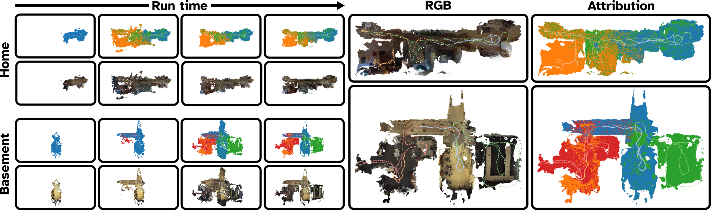
V-B1 Map Reconstruction
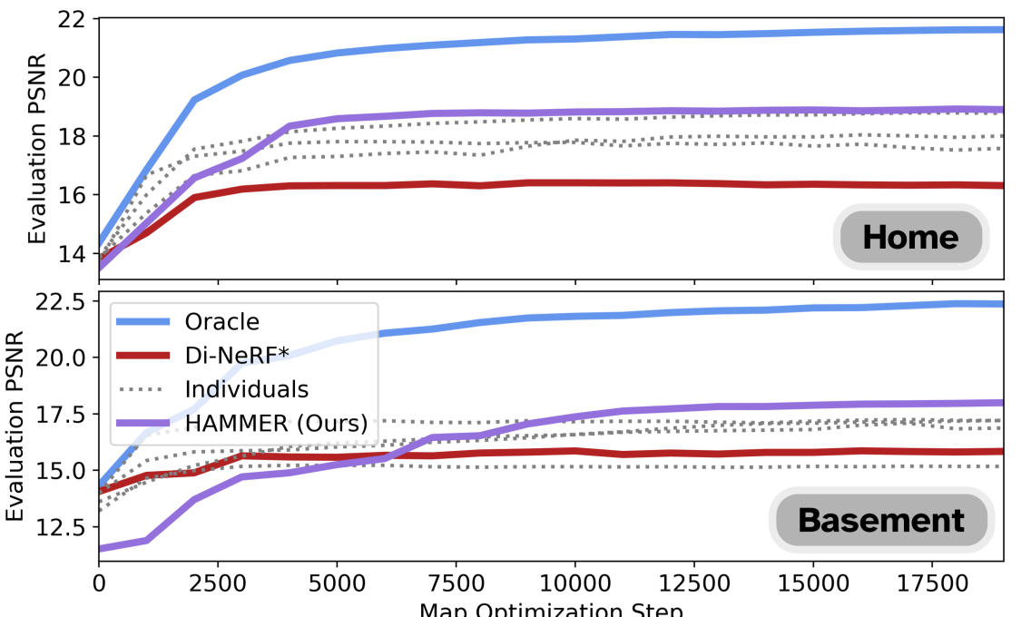
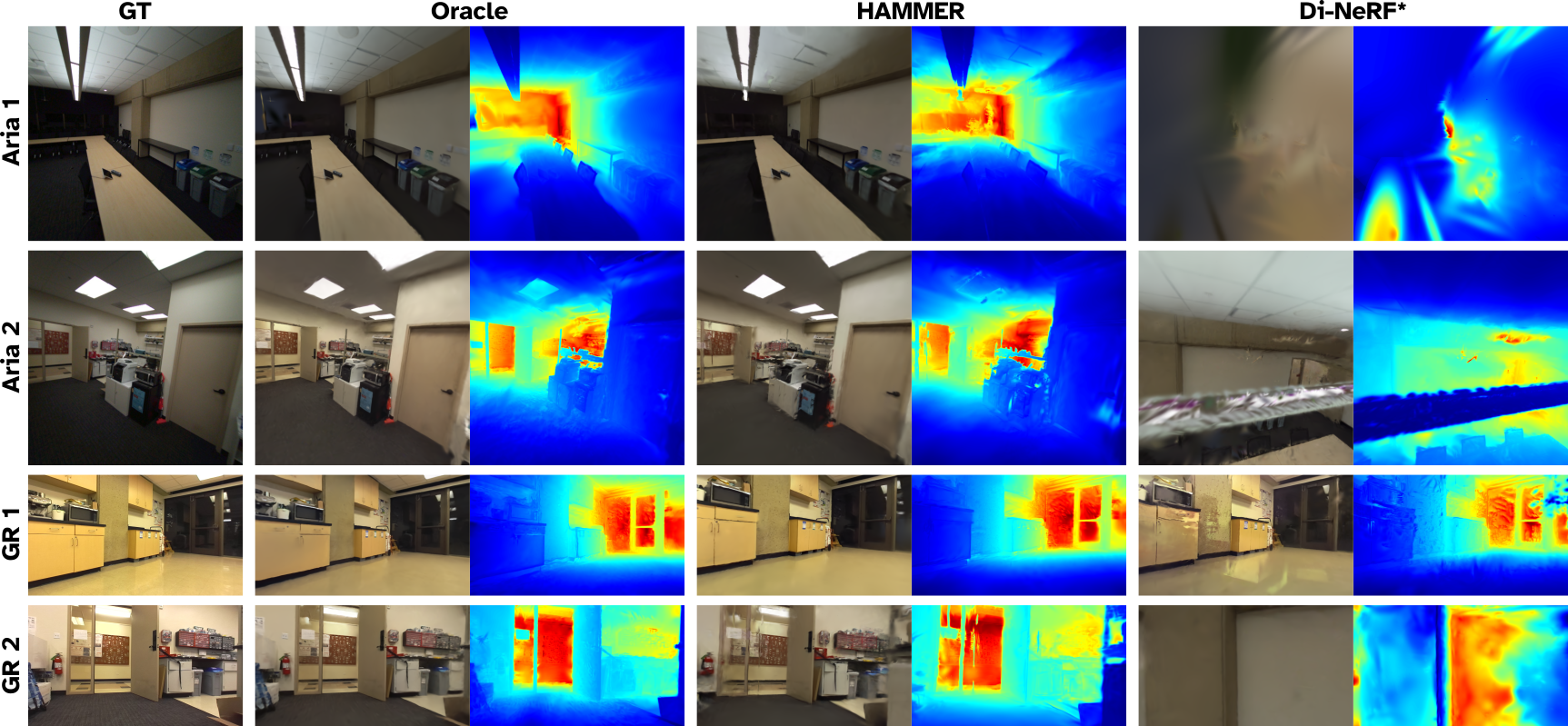
Figure 3 visualizes meshes extracted from the DGS maps constructed by HAMMER as they evolve with time during the online map optimization process. Embedded in the meshes are trajectories taken by each robot during deployment, highlighting where each robot contributed data and the overall spatial distribution of data. Qualitatively, HAMMER demonstrates superior photo-realistic renders on the evaluation set (Figure 5) compared to Di-NeRF*, which fails to resolve robot alignments and therefore cannot accurately match the ground-truth images. HAMMER also approaches the quality of the Oracle baseline.
We quantify reconstruction quality based on the average peak signal to noise ratio (PSNR) of each method on the held-out evaluation data set (Figure 4). HAMMER dramatically outperforms Di-NeRF*, suggesting that the gradient-based alignment of Di-NeRF fails to converge to accurate inter-robot alignments. The set of Individuals baselines underperforms HAMMER as expected, highlighting the benefit of robot collaboration in map building. Note that the performance of some individual maps is relatively high due to good performance on their respective evaluation sets, but degrade drastically when benchmarked on another robot’s evaluation set. Finally, as expected, Oracle is an upper bound on the performance of HAMMER but is significantly slower.
V-B2 Runtime
HAMMER runtime is dominated by the DGS map optimizer and the inter-robot alignment module. Processing a single data-frame in the map optimizer ranges between 15 ms (66 Hz) when the map is sparsely populated to 38 ms (26 Hz). Slower iterations typically occur immediately after a robot has been aligned and all of its cached data is consolidated into the map. The runtime of the alignment module is dominated (90% - 99.5% of the runtime) by the localized SfM procedure. Each SfM alignment requires about 33.6s to solve. The remaining runtime is primarily the feature-matching based verification for proposed image correspondences (approximately 2.6s).
V-B3 Multi-robot Semantic Motion Planning
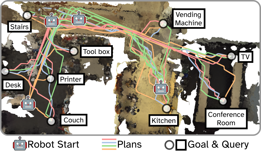
We demonstrate the utility of HAMMER for collaborative downstream tasks by completing a multi-robot motion planning task with language-specified goals in Basement using a HAMMER DGS map. To set a goal location, we query an object’s location using natural language. Then, using CLIP, we extract the semantic embedding for the goal query and search the HAMMER DGS map for the most semantically similar Gaussian using cosine similarity. Next, we sample the surrounding space for a nearby location in free space, which we set as the goal location. Once a goal is specified, we use Splat-Nav [7] to plan a collision-free trajectory from the initial position of each robot to the goal location. Figure 6 shows optimized trajectories for each of the four robots in Basement with 9 semantically-specified goals. Searching the map for each semantic goal location required about 20ms, and the subsequent trajectories were computed within 0.2s to 0.75s depending on the distance to the goal. All robots successfully completed the task.
VI Conclusion and Limitations
HAMMER is the first online multi-robot Gaussian Splatting mapping pipeline, built for heterogeneous robot teams. Maps produced with HAMMER can be used for a variety of downstream tasks such as language-guided navigation. We show that HAMMER outperforms comparable baselines on real datasets and approaches the visual fidelity of an oracle. Future work will focus on better methods for data curation, reducing the volume of redundant data, and enabling detailed scene reconstructions over larger areas. We hope to extend HAMMER to track and map dynamic objects, and leverage the semantics embedded in the HAMMER map to extract intelligent spatial relationships between objects.
HAMMER has several limitations. Devices which do not provide pose estimates cannot be used in HAMMER, and very noisy estimates cannot be rectified by HAMMER’s pose refinement and produce a poor quality map. Moreover, the current implementation of HAMMER does not account for RGB-only devices (no geometric data). However, we believe HAMMER can be extended for use in RGB-only DGS SLAM, an active research area.
References
- [1] J. Engel, K. Somasundaram, M. Goesele, A. Sun, A. Gamino, A. Turner, A. Talattof, A. Yuan, B. Souti, B. Meredith et al., “Project aria: A new tool for egocentric multi-modal ai research,” arXiv preprint arXiv:2308.13561, 2023.
- [2] B. Mildenhall, P. P. Srinivasan, M. Tancik, J. T. Barron, R. Ramamoorthi, and R. Ng, “Nerf: Representing scenes as neural radiance fields for view synthesis,” Communications of the ACM, vol. 65, no. 1, 2021.
- [3] B. Kerbl, G. Kopanas, T. Leimkühler, and G. Drettakis, “3d gaussian splatting for real-time radiance field rendering,” ACM Transactions on Graphics, vol. 42, no. 4, pp. 1–14, 2023.
- [4] H. Matsuki, R. Murai, P. H. Kelly, and A. J. Davison, “Gaussian splatting slam,” in Proceedings of the IEEE/CVF Conference on Computer Vision and Pattern Recognition, 2024, pp. 18 039–18 048.
- [5] T. Chen, A. Swann, J. Yu, O. Shorinwa, R. Murai, M. Kennedy III, and M. Schwager, “Safer-splat: A control barrier function for safe navigation with online gaussian splatting maps,” arXiv preprint arXiv:2409.09868, 2024.
- [6] O. Shorinwa, J. Tucker, A. Smith, A. Swann, T. Chen, R. Firoozi, M. D. Kennedy, and M. Schwager, “Splat-mover: multi-stage, open-vocabulary robotic manipulation via editable gaussian splatting,” in 8th Annual Conference on Robot Learning, 2024.
- [7] T. Chen, O. Shorinwa, W. Zeng, J. Bruno, P. Dames, and M. Schwager, “Splat-nav: Safe real-time robot navigation in gaussian splatting maps,” arXiv preprint arXiv:2403.02751, 2024.
- [8] B. Xiong, Z. Li, and Z. Li, “Gauu-scene: A scene reconstruction benchmark on large scale 3d reconstruction dataset using gaussian splatting,” arXiv preprint arXiv:2401.14032, 2024.
- [9] X. Zhou, Z. Lin, X. Shan, Y. Wang, D. Sun, and M.-H. Yang, “Drivinggaussian: Composite gaussian splatting for surrounding dynamic autonomous driving scenes,” in Proceedings of the IEEE/CVF Conference on Computer Vision and Pattern Recognition, 2024, pp. 21 634–21 643.
- [10] J. Yu, K. Hari, K. Srinivas, K. El-Refai, A. Rashid, C. M. Kim, J. Kerr, R. Cheng, M. Z. Irshad, A. Balakrishna et al., “Language-embedded gaussian splats (legs): Incrementally building room-scale representations with a mobile robot,” arXiv preprint arXiv:2409.18108, 2024.
- [11] O. Shorinwa, T. Halsted, J. Yu, and M. Schwager, “Distributed optimization methods for multi-robot systems: Part 2—a survey,” IEEE Robotics & Automation Magazine, 2024.
- [12] M. Asadi, K. Zareinia, and S. Saeedi, “Di-nerf: Distributed nerf for collaborative learning with relative pose refinement,” IEEE Robotics and Automation Letters, 2024.
- [13] J. T. Barron, B. Mildenhall, M. Tancik, P. Hedman, R. Martin-Brualla, and P. P. Srinivasan, “Mip-nerf: A multiscale representation for anti-aliasing neural radiance fields,” in Proceedings of the IEEE/CVF international conference on computer vision, 2021, pp. 5855–5864.
- [14] T. Müller, A. Evans, C. Schied, and A. Keller, “Instant neural graphics primitives with a multiresolution hash encoding,” ACM Transactions on Graphics (ToG), vol. 41, no. 4, pp. 1–15, 2022.
- [15] J. L. Schönberger and J.-M. Frahm, “Structure-from-motion revisited,” in Conference on Computer Vision and Pattern Recognition, 2016.
- [16] N. Keetha, J. Karhade, K. M. Jatavallabhula, G. Yang, S. Scherer, D. Ramanan, and J. Luiten, “Splatam: Splat track & map 3d gaussians for dense rgb-d slam,” in Proceedings of the IEEE/CVF Conference on Computer Vision and Pattern Recognition, 2024, pp. 21 357–21 366.
- [17] Y. Huang, T. Shan, F. Chen, and B. Englot, “Disco-slam: Distributed scan context-enabled multi-robot lidar slam with two-stage global-local graph optimization,” IEEE Robotics and Automation Letters, vol. 7, no. 2, pp. 1150–1157, 2021.
- [18] Y. Tian, Y. Chang, F. H. Arias, C. Nieto-Granda, J. P. How, and L. Carlone, “Kimera-multi: Robust, distributed, dense metric-semantic slam for multi-robot systems,” IEEE Transactions on Robotics, vol. 38, no. 4, 2022.
- [19] Y. Chang, K. Ebadi, C. E. Denniston, M. F. Ginting, A. Rosinol, A. Reinke, M. Palieri, J. Shi, A. Chatterjee, B. Morrell et al., “Lamp 2.0: A robust multi-robot slam system for operation in challenging large-scale underground environments,” IEEE Robotics and Automation Letters, vol. 7, no. 4, pp. 9175–9182, 2022.
- [20] Y. Deng, Y. Tang, Y. Yang, D. Wang, and Y. Yue, “Macim: Multi-agent collaborative implicit mapping,” IEEE Robotics and Automation Letters, 2024.
- [21] H. Zhao, B. Ivanovic, and N. Mehr, “Distributed nerf learning for collaborative multi-robot perception,” arXiv preprint arXiv:2409.20289, 2024.
- [22] W. Wang, V. Cai, and S. Gil, “Mulan-wc: Multi-robot localization uncertainty-aware active nerf with wireless coordination,” arXiv preprint arXiv:2403.13348, 2024.
- [23] V. Yugay, T. Gevers, and M. R. Oswald, “Magic-slam: Multi-agent gaussian globally consistent slam,” arXiv preprint arXiv:2411.16785, 2024.
- [24] R. Arandjelovic, P. Gronat, A. Torii, T. Pajdla, and J. Sivic, “Netvlad: Cnn architecture for weakly supervised place recognition,” in Proceedings of the IEEE conference on computer vision and pattern recognition, 2016, pp. 5297–5307.
- [25] D. DeTone, T. Malisiewicz, and A. Rabinovich, “Superpoint: Self-supervised interest point detection and description,” in Proceedings of the IEEE conference on computer vision and pattern recognition workshops, 2018, pp. 224–236.
- [26] P. Lindenberger, P.-E. Sarlin, and M. Pollefeys, “Lightglue: Local feature matching at light speed,” in Proceedings of the IEEE/CVF International Conference on Computer Vision, 2023, pp. 17 627–17 638.
- [27] P.-E. Sarlin, D. DeTone, T. Malisiewicz, and A. Rabinovich, “Superglue: Learning feature matching with graph neural networks,” in Proceedings of the IEEE/CVF conference on computer vision and pattern recognition, 2020, pp. 4938–4947.
- [28] S. Umeyama, “Least-squares estimation of transformation parameters between two point patterns,” IEEE Transactions on Pattern Analysis & Machine Intelligence, vol. 13, no. 04, pp. 376–380, 1991.
- [29] L. Yang, B. Kang, Z. Huang, X. Xu, J. Feng, and H. Zhao, “Depth anything: Unleashing the power of large-scale unlabeled data,” in CVPR, 2024.
- [30] A. Radford, J. W. Kim, C. Hallacy, A. Ramesh, G. Goh, S. Agarwal, G. Sastry, A. Askell, P. Mishkin, J. Clark et al., “Learning transferable visual models from natural language supervision,” in International conference on machine learning. PMLR, 2021, pp. 8748–8763.
- [31] C. Zhou, C. C. Loy, and B. Dai, “Extract free dense labels from clip,” in European Conference on Computer Vision. Springer, 2022, pp. 696–712.
- [32] M. Qin, W. Li, J. Zhou, H. Wang, and H. Pfister, “Langsplat: 3d language gaussian splatting,” in Proceedings of the IEEE/CVF Conference on Computer Vision and Pattern Recognition, 2024, pp. 20 051–20 060.
- [33] Y. Wang, C. Wang, B. Gong, and T. Xue, “Bilateral guided radiance field processing,” ACM Transactions on Graphics (TOG), vol. 43, no. 4, pp. 1–13, 2024.
- [34] M. Quigley, K. Conley, B. Gerkey, J. Faust, T. Foote, J. Leibs, R. Wheeler, A. Y. Ng et al., “Ros: an open-source robot operating system,” in ICRA workshop on open source software, vol. 3. Kobe, Japan, 2009, p. 5.
- [35] J. Yu, J. E. Low, K. Nagami, and M. Schwager, “Nerfbridge: Bringing real-time, online neural radiance field training to robotics,” arXiv preprint arXiv:2305.09761, 2023.