Hardcaml: An OCaml Hardware Domain-Specific Language for Efficient and Robust Design
Abstract
This paper introduces Hardcaml, an embedded hardware design domain specific language (DSL) implemented in the OCaml programming language. Unlike high level synthesis (HLS), Hardcaml allows for low level control of the underlying hardware for maximum productivity, while abstracting away many of the tedious aspects of traditional hardware definition languages (HDLs) such as Verilog or VHDL. The richness of OCaml’s type system combined with Hardcaml’s fast circuit elaboration checks reduces the chance of user-introduced bugs and erroneous connections with features like custom type defining, type-safe parameterized modules and elaboration-time bit-width inference and validation. Hardcaml tooling emphasizes fast feedback through simulation, testing, and verification. It includes both a native OCaml cycle-accurate and an event-driven simulator. Unit tests can live in the source code and include digital ASCII waveforms representing the simulator’s output. Hardcaml also provides tools for SAT proving and formal verification. Hardcaml is industrially proven, and has been used at Jane Street internally for many large FPGA designs. As a case study we highlight several aspects of our recent Hardcaml submission to the 2022 ZPrize cryptography competition which won 1st place in the FPGA track.
Keywords CAD, RTL, Hardware Domain-Specific Languages, Efficiency, Robustness, FPGA
1 Introduction
(System) Verilog and VHDL are currently the most commonly used hardware definition languages (HDLs) used in industry. Despite being expressive enough to create hardware circuits, these languages have significant differences from software languages; they have correspondingly not benefited from advances in programming language design. These advances improve productivity and flexibility, and are also crucial to hardware design as systems become much more large and complex. In modern hardware development, the bulk of a hardware designer’s time is spent in modeling, simulation, and testing [Joshi et al.(1995)].
A large number of existing domain-specific languages (DSLs) [George et al.(2014), Kapre and Bayliss(2016)] aim at solving the various shortcomings of Verilog and VHDL. Each of these provide different levels of abstraction and control of underlying hardware primitives, guarantees of safety, and additional features or meta-programming. The advantages of using such DSLs have been shown empirically. An example RISC-V core design that required 1000 lines of hand-written Verilog required only 586 lines of Chisel [Im and Kang(2021)], and a similar design required 637 lines of Hardcaml [Tatachar(2022)]. Reducing the number of lines of code a designer has to write increases productivity and decreases the chance for bugs. There is also a great interest in translating traditional RTL designs into the domain of these DSLs [Bruant et al.(2020)].
Existing DSLs can be divided into two main categories in terms of their abstraction from the underlying RTL– compiler style DSLs and full control DSLs. Compiler style DSLs allow the designer to express a circuit in terms of dataflow or a higher level language such as C++, which the DSL framework compiles to RTL. This increases productivity in hardware design by fast iteration over potentially large design spaces containing many different parameters, at the cost of preventing fine clock cycle-level control and optimization. These are often referred to as high level synthesis (HLS) tools, and can be stand-alone tools such as Vivado HLS, PyLog [Huang et al.(2021)], or wrappers around existing tool chains and general-purpose compiler infrastructure [Thomas(2016), Ye et al.(2022)] such as MLIR [Lattner et al.(2020)]. For example Bluespec [Nikhil and Arvind(2008), Nikhil(2004)] allows design using lists of declarative rules, which each fire automatically with handshaking to control data flow.
Full control DSLs allow writing hardware that can directly instantiate hardware primitives such as registers, memories, multiplexors, and so on. They allow the designer to optimize a circuit down to clock-cycle latencies, while offering improvements on top of traditional HDL languages via software language paramertization and meta-programming. Hardcaml is a full control DSL. Other full control DSLs are Filament [Nigam et al.(2023)], which while only currently supporting statically scheduled pipelines, allows for the safe reusability of modules through timeline types that encode latency and throughput. Chisel [Bachrach et al.(2012)], Clash [Baaij et al.(2010)], SpinalHDL [Ruep and Große(2022)], MyHDL [Villar et al.(2011)] provide similar parametrization to Hardcaml, but each has a slightly different toolkit it exposes to the designer.
OCaml modules and functors provide flexible circuit parameterization in Hardcaml. Both the type system and an extensive testing and verification toolkit ensure safety and correctness. Circuit elaboration is fast and happens during both RTL generation and simulation, completely inside OCaml. During elaboration Hardcaml ensures there are no floating wires, no multiple drivers, and when signals do connect that their widths match exactly. The combination of these allow for RTL design that avoids common place bugs, allowing an engineer to spend more time on the enjoyable and valuable areas of hardware design.
Both a built-in cycle-accurate and event-driven simulator allows for unit level tests alongside the Hardcaml source code, which can optionally print digital ASCII waveforms. These tests provide fast feedback on designs and help catch future bugs. Hardcaml can generate hardware design from abstraction models written in OCaml, simulation expect-tests with waveforms, interactive waveform viewers, synthesis reports, and finally allow production-ready Verilog and/or VHDL.
The development flow for hardware development in Hardcaml is very similar to software development. The availability of Hardcaml simulators and various tooling, along with the existing OCaml Dune build system [dun(2023)] and availability of various OCaml libraries, draws testing and simulation into the ordinary software development life cycle. The comprehensive testing capabilities, all within a single programming language, allow for rapid hardware development with a fast feedback loop in simulation.
While existing DSLs address different aspects of safety and productivity, Hardcaml does this while providing the hardware engineer with a more contained and complete solution. Other DSLs do not include as comprehensive testing capabilities such as unit test waveforms or built-in simulators. Each DSL is implemented inside a higher level software language, which can ultimately define its capabilities and limitations. OCaml is a strongly typed and modern functional programming language, and Hardcaml is entirely embedded inside OCaml without the need for any secondary abstraction layer. This allows Hardcaml to be lightweight and makes it easier to develop improvements or debug issues directly in the source code. Hardcaml is an actively maintained open-source [Street(2023)] project developed at Jane Street, where it’s the primary system used for creating production FPGA designs.
2 Hardcaml Overview
Hardcaml is a DSL embedded in OCaml that improves reliability when writing HDL, while remaining light weight and easy to use. OCaml is a multi-paradigm (functional, imperative, object-oriented) high level programming language with an expressive type system and type inference. Hardcaml is a collection of OCaml libraries that designers can use to express circuits with the same amount of control as Verilog or VHDL, but with the advantages of a higher-level programming language. It cuts out a lot of the mundane error-prone work when connecting modules and parameterizing circuits, as will be demonstrated. A strong built-in linter prevents bugs such as signals of different widths driving each other, and detects floating and multiple drivers.
The typical workflow of designing with Hardcaml is as follows:
-
1.
Write the circuit implementation using Hardcaml libraries.
-
2.
Compose testbenches, which are run using the built-in Hardcaml simulator.
-
3.
Debug using the built-in terminal-based waveform viewer and expect-tests.
-
4.
Generate Verilog from OCaml using the built-in Hardcaml RTL generator.
-
5.
Run generated Verilog through standard vendor tooling (Vivado, etc.).
Steps 1-3 can leverage existing OCaml tooling such as the Dune build system [dun(2023)] for rapid development.
2.1 Datatypes
The core type in a Hardcaml circuit is the Signal.t type. Various functions
and operators that take Signal.t as parameters represent hardware primitives.
Table 1 shows a few examples of these.
+:, +:.
|
Addition operator |
|---|---|
-:, -:.
|
Subtraction operator |
&: |
Bitwise AND operator |
|: |
Bitwise OR operator |
==:, ==:.
|
Equality operator |
reg, reg_spec |
Registers and clock/clear specification |
mux2, mux
|
Multiplexors |
All operators contain a : to distinguish them between regular OCaml operators on
integers, as OCaml does not support operator overloading. There are multiple variants of
arithmetic operators (eg: +: and +:.). The +: and +:.
operators both represent addition. +: operates on two Signal.ts that must
match bit-width, while +:. operates on a Signal.t and integer that has its
bit-width inferred. reg_specs specify clock and clear signals for sequential logic
such as regs. mux is a general multiplexor that takes a list of arguments,
and mux2 is a convenient helper function to write a simple if-then-else multiplexor
with two cases.
The programmer can create a hardware circuit by calling functions on a value of type
Signal.t, and then storing the returned value (which is also a Signal.t). For example,
the following function creates a counter that counts to count_to and then wraps back to
zero.~ is used to pass a named argument to a function, and
() is sometimes necessary to terminate a sequence of function arguments in
OCaml.
The code listing above constructs a counter which behaves similarly to the Verilog code snippet below.
The advantage of using Hardcaml here is it will prevent the counter output connecting to something that isn’t wide enough, which if happened in Verilog would silently drop the unused bits.
2.2 Defining New Types
Hardcaml can represent each logical idea in its own type, defined by the programmer.
OCaml’s type system then statically guarantees that values of a given type cannot be used
in ways other than those defined valid for that type. This enables both abstraction and
eliminates entire classes of potential errors. Note that these types are parameterized
with ’a, later to be replaced with Signal.ts. For example, the following
Hardcaml snippet defines a type called Rectangle.t, which has a 10-bit length and a
6-bit width. Signal.t Rectangle.t is similar to a Rectangle<Signal>
in Java or C++. A parameterized type argument allows us to use Rectangle.t in
different contexts, like tests, debugging, and HDL generation.
You can then write a function that takes a Rectangle.t as an argument. This snippet
would generate a circuit that outputs the area of a given rectangle.
[@@deriving hardcaml] instructs the Hardcaml preprocessor to generate utility
functions working with the Rectangle.t type. The derived Rectangle.map
function applies a function to every field. For example, this function returns
a rectangle where both the length and width are increased by a certain size.
Another derived function is Rectangle.Of_signal.priority_select, which
performs a combinational priority select on the custom rectangle type. For example, this
function takes a list of rectangles and outputs the first rectangle whose width is greater
than threshold. It uses List.map to convert the Rectangle.t inputs to With_valid.t
objects. A With_valid.t object contains an input rectangle (value) and a single bit
indicating whether the priority select should accept the input (valid).
Custom types can be nested arbitrarily to create multiple layers of logical separation. For example:
Another abstract type that one would define is a scalar-type. These are bit-vectors of a
particular width that have logical meaning. For example, we can define a 32-bit price in
US dollars. It’s important that we don’t use values of this type when we’re expecting, for
example, Euros. We then can define some custom functions that operate on this type, namely is_gte_zero,
min, and max. Including the module Types.Scalar creates a type Price_in_usd.t and common functions on that type.
Functions can be defined to explicitly expect a value of type Price_in_usd.t,
rather than an arbitrary value of type Signal.t.
The OCaml compiler will permit the following.
On the other hand, the OCaml compiler will emit a compile-time error due to a type mismatch in the following code snippet. This is an important safety feature of Hardcaml as it prevents the programmer from passing values of unexpected types into functions.
Here is another example of a compile-time error due to a type mismatch as the
programmer uses the type Signal.t Rectangle.t instead of
Signal.t Price_in_usd.t, producing the error
These scalar types can also be nested within interfaces.
2.3 Hierarchical Modules
A Hardcaml circuit module can be structured similar to a Verilog circuit module.
Using the hierarchy library inside Hardcaml, a global circuit
hierarchy can be constructed. This produces simulation waveforms with
hierarchical signals which increases debugging productivity, and generates
RTL with hierarchical modules, which works better with existing
Verilog and VHDL-based vendor tooling.
To define a Hardcaml circuit module, the programmer defines I and O
modules, corresponding to the input and output interfaces. Then, the programmer
defines a create function that when given Signal.t I.t, returns
Signal.t O.t.
For example:
2.4 Bit-width Inference and Post Processing Validation
Hardcaml handles bit-width strictly. The circuit construction step validates bit-widths for all operations before running simulations or generating Verilog. This prevents many errors at the compilation stage, increasing the speed of the designer’s feedback loop. For example, the following program will fail due to a width mismatch:
Hardcaml can also infer the bit-width for most operations, so users don’t need to specify the width for most internal wires. In the case above we specifically resized our wires to 32-bits and 16-bits.
For example, Hardcaml will infer the width of mult_result as width a + width b
and the width of eq_result as 1.
During circuit elaboration, Hardcaml also performs other validation, ensuring that:
-
•
Module instantiations have appropriate port widths.
-
•
All wires have exactly one driver.
-
•
Operation bit-widths match.
These errors are caught early on before simulation is run or RTL is generated.
2.5 The Always DSL
Hardcaml includes the Always DSL, which can describe circuits in the same style as a Verilog always block. Signals are now inside guarded assignments, either as asynchronous wires or synchronous regs. The Always DSL does not support blocking assignments. Below we show an example of an accumulating sum state machine written in this style. This module will add and accumulate all inputs provided as long as any input is non-zero.
First we define a clock and clear module Control which will ensure other modules
types cannot drive this circuit. This is then combined with our data inputs which is an
OCaml list of signals, each with a bit-width of 4. Our output is a single signal of
bit-width 4.
We then define the the states our circuit can be in with the module State, which
are Idle and Adding. We use the preprocessor to automatically derive
functions that let Hardcaml internally compare and enumerate in order to implement the state machine.
The Always DSL create function takes this module as its input and returns
sm, the control object of our state machine.
Inside the create function’s control input, we have expanded out the
clock and clear inputs, which means the named arguments for
Reg_spec.create match and do not need to be specified, reducing the chance of a
connection typo.
We then declare the output O.t as an always reg– this means we can use the
Always DSL logic assignment operator (<--) to assign values to our output from
within our state machine. For each state, we add logic for transitioning to new states and
assigning output values. We use the Hardcaml tree and reduce functions to
construct a log2 tree that will sum elements. This demonstrates how optimized data
structures can be used with low effort on the designers part. The preprocessor generates a
function O.Of_always.value that converts our always reg to a Signal.t O.t.
The Always DSL allows for further abstraction by using OCaml functions. This also can provide implicit documentation via function names in complicated state machines.
2.6 Module-Level Parameterization with Functors
In OCaml a functor is a module that takes one or more modules as a parameter, and returns a new module. These allow us to parameterize Hardcaml circuits, similar to Verilog’s parameters. The programmer first defines a config argument for the parameterized module. For example:
Then, they can define the corresponding circuit and module using fields
(metadata_bits) or datatypes (Data.t) from the functor argument.
The module Make below is an OCaml functor.
The functor can then be instantiated with an argument of the appropriate type signature. For example:
This is similar to parameterized circuits in Verilog. The key advantage
to this functor-style is that the parameters themselves can be arbitrary arguments, such
as lists, integers, arrays or even custom types (Data.t in the above case).
This allows for high expressiveness in parameter descriptions. When instantiating
the Make functor, the OCaml compiler will ensure that the provided
argument value matches its expected type.
Functors, as demonstrated above, are a powerful feature in OCaml that allows modularity and parametrization. This demonstrates an advantage of Hardcaml being embedded in a programming language: it allows the programmer to leverage existing software-level features for hardware design.
2.7 Example Circuit Descriptions
Below are some examples of circuit description that demonstrate Hardcaml’s expressiveness.
2.7.1 Tree Adder
Recursive circuits in Hardcaml come very naturally. The following circuit decomposes
operands into a tree and performs an arbitrary associative operation op on them:
The tree_op can be used to construct various a tree of associatative
operators, such as a tree adder or a tree AND.
Note that in practice, tree-like constructs can be expressed using the
tree function. The example above serves to illustrate a recursive
example.
2.7.2 Constructing a Linear Feedback Shift Register
A Linear Feedback Shift Register (LFSR) is a shift register whose input bit is the XOR of 2 of more bits (taps) of it’s previous state. This can be expressed in Hardcaml as follows:
The constructed LFSR x behaves identically to the following Verilog code
snippet:
2.7.3 Constructing a RAM
Hardcaml has built-in support for constructing memories, which are inferrable by backend tools like Vivado. Models are provided for both simulation and synthesis, which have been verified against vendor-provided RTL using the formal proving libraries provided with Hardcaml and discussed in section 2.9.3.
2.7.4 Constructing an ROM
A ROM can be defined from an arbitrary OCaml math function as follows. This means that
Hardcaml is able to leverage the wide range of mathematical libraries available in the
OCaml ecosystem, for example math, float, and owl (which provides sparse matrix and linear algebra functions).
2.8 Fixed Point Support
Hardcaml also provides the hardcaml_fixed_point library, with support for hardware-synthesizable
arithmetic operations such as +, -, and *. It provides a rich set of rounding and
clamping modes, and seperate types for performing signed or unsigned operations. This
library is useful for many signal processing applications, where explicit control over
integer and fractional bit-widths is required. Functors can be used with
this library to implement and experiment different bit-widths and the resulting change of output precision.
2.9 Testing and Simulation
One of the aspects of Hardcaml that sets it apart from other DSLs is its emphasis and support for circuit testing, simulation, and verification. The next sections highlight the technologies that are provided with Hardcaml for this purpose.
2.9.1 Expect-test Simulations and Waveforms
The ability to simulate circuits, view resulting waveforms, and fix any bugs are important parts of the workflow. While many other DSLs in this space require transformation through an intermediate form and the use of external simulators and waveform display tools [Ruep and Große(2022), Bachrach et al.(2012)], Hardcaml supports direct simulation of the circuit graph inside OCaml. The cycle-based simulator has been optimized for runtime performance, and common primitive bit-level manipulation is done via fast OCaml Foreign Function Interface (FFI) calls into C.
OCaml tests are written in a ”snapshot” style, where statements can be
immediately followed by an [%expect] block that prints that statement’s
output. Any changes in the code that affect this frozen output are detected as
test failures. Hardcaml integrates into this flow seamlessly, and circuit inputs and outputs
can be printed at any cycle in the simulation.
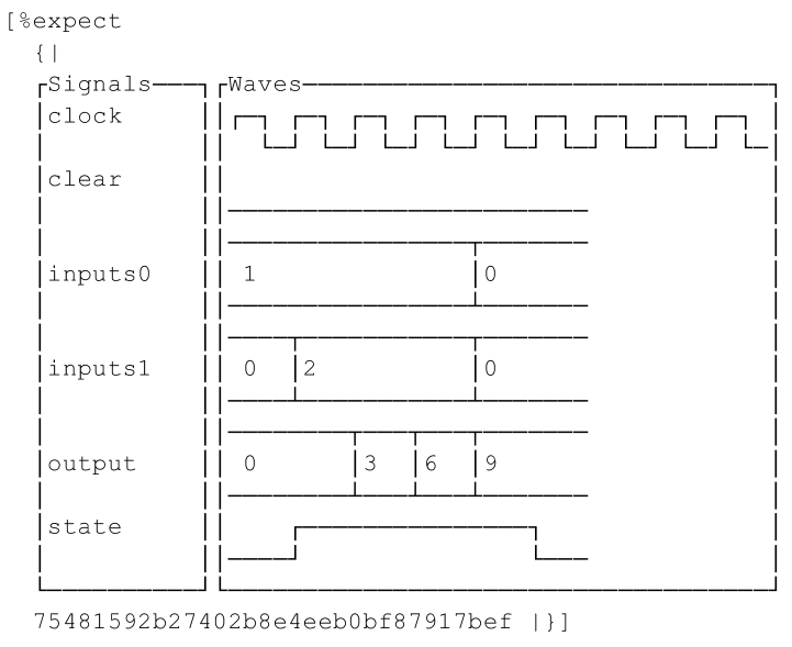
Waveterm is one of Hardcaml’s many supporting libraries. It can print ASCII waveforms over
a given number of cycles, and it can also operate as a stand-alone tool for interactive
use. It can also be integrated into project-specific testing binaries. The advantage of
ASCII waveforms is that they can be included in expect-test output. This helps users
understand how Hardcaml functions work. It also makes clear how changes in source code
change test outputs, which makes breaking changes easier to detect. This is also helpful
when reviewing changes submitted to a version-control repository, since the reviewer can
directly see how the code changes affect the output. This will also allow for quick
detection of any unwanted changes to source code that cause existing circuits tests to
fail. Figure 1 shows an example output of this type of test, on the adder
state-machine circuit previously introduced. Here we are assigning to our inputs with the
Bits.t type, which is used to drive circuit inputs and can take concrete values.
2.9.2 Integration into Other Simulation Backends
In addition to the built-in simulator Cyclesim provided, Hardcaml also allows for seamless
simulation into two other backends - hardcaml_c and hardcaml_verilator
(Verilator version 5.0.14 [Snyder(2023)]). These provide better simulation performance at
the expense of a longer compilation time. hardcaml_c uses even more bindings to C
for the circuit evaluation operations, and hardcaml_verilator compiles the circuit
to a shared object and calls into a Verilator binary. When the simulation is complete, the
backend sends the results back to the Hardcaml framework, which displays them in the same
waveform viewers and debugging tools used with the built-in simulator. The user doesn’t
need to change their workflow, other than calling a different simulator function. By
allowing seamless integration into these backends, simulation runtime can be optimized
depending on the size and number of input stimuli. Table 2 shows a
comparison of the available backends. We created a large board-level network passing circuit in Hardcaml, which generated 180k lines of Verilog.
We measured simulation and compile times for 100, 1000, and 10,000 packets.
| Packets | Simulation time (s) | ||
|---|---|---|---|
| Cyclesim | Cyclesim_c | Verilator | |
| 100 | 6 | 8 | 2 |
| 1,000 | 43 | 20 | 3 |
| 10,000 | 419 | 138 | 17 |
| Compilation time (s) | 1 | 8 | 263 |
2.9.3 Hardcaml Verify
When designing circuits where correctness is paramount, more detailed
verification is required. The library hardcaml_verify provides many tools for the user:
-
•
SAT solvers can check the equivalence of combinational circuits and identify error cases.
-
•
The Bounded Model Checker can check the equivalence of two sequential circuits, up to a given number of clock cycles.
-
•
NuSMV [Cimatti et al.(2002)] integrates with Hardcaml to prove LTL assertions. While this is slow and works better for small circuits, Hardcaml makes it possible to parameterize the size of the circuit, so NuSMV can prove assertions for small versions of the circuit.
2.9.4 Built-in Synthesis Reports
Hardcaml also has a built-in synthesis report utility. This allows visualizing hierarchical synthesis results of Hardcaml circuits by running them through backend tools. For example, the programmer can setup a synthesis executable for the design below, which instantiates multiple Hardcaml modules.
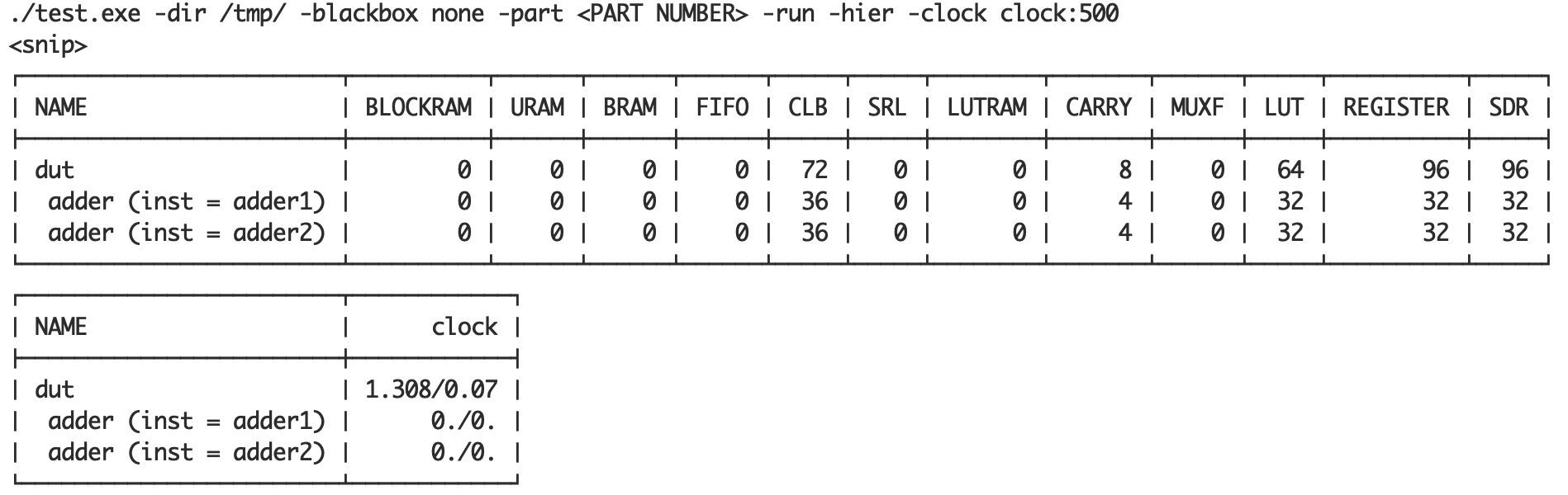
The user can then run the executable to obtain a table with the timing summary and resource utilization of the synthesis results, as show in an example in figure 2. The ease of running this tool lowers the barriers to running synthesis on small circuits. There are also more options available to control the output artifacts, such as running place and route on top of synthesis, or generating intermediate design checkpoint files.
2.10 Drawbacks of Hardcaml
Although Hardcaml has been able to build upon the advantages other DSLs offer, there are still several shortcomings when compared to Verilog and VHDL.
-
•
Unless specifically labeled, the mapping of Hardcaml function calls to their generated RTL might not be obvious to a user, which can be important when debugging timing violations in Vivado.
-
•
Interfacing with externally written IP cores requires blackbox wrappers in Hardcaml which can’t be simulated, without doing additional work such as importing the RTL into Hardcaml.
-
•
The user may not be familiar with functional programming or OCaml.
2.11 Future Work
We are continuously adding new features to Hardcaml and releasing improvements into open source repositories. We plan to implement the following new features that will further differentiate Hardcaml from other DSLs:
Encoding Signal Clock-Domains within the Type System
Currently, the entire design of a Hardcaml circuit uses the same Signal.t type. A
more advanced approach is to constrain Signal.t to a particular clock domain using
a functional programming technique called phantom types. This uses the type system to
ensure that the programmer did not accidentally mix signals between different clock
domains. When cross-clock-domain crossing is necessary, signals can be marked as such and
this validation will be relaxed. This can provide a balance between clock-domain-safety
and flexibility in real-world designs.
Floating Point Support
We are implementing a suite of floating point cores, including adders, multipliers, fixed-point converters, and more. We will provide these in the open-source Hardcaml suite when they are ready.
Integration with Higher-Level HDLs
As mentioned in the introduction, some HDLs like Filament [Nigam et al.(2023)] and Bluespec [Nikhil and Arvind(2008)] trade-off low-level control for a higher level of abstraction. A seamless integration (eg: within a Hardcaml library) between Hardcaml circuits with low-level control and these HDLs can potentially further improve programmer productivity by giving them more tools in the Hardcaml development environment. This will include features like a user-friendly API to construct circuits in those HDLs, rapid circuit-elaboration-time validation, integration with Hardcaml’s existing simulation frameworks, and RTL generation.
3 A Case Study into Using Hardcaml
We designed a Multi-Scalar Multiplication (MSM) engine written entirely in Hardcaml, Hardcaml MSM. In this section we compare and highlight several of the design techniques from Hardcaml that enabled us to efficiently design this engine with a tight deadline and limited human resources.
3.1 Config Functorization
We used the Config module, shown below, to parameterize our design. We could easily
change bit widths, window bounds, and circuit partitioning over the 3 Super Logic Regions
(SLRs) available to us on the FPGA. Within seconds of making a change, the Dune build
system would tell us if any of our tests failed, or if our design’s performance changed.
In Verilog, we would not have been able to parameterize our design to this degree, and
iterating over the design space would have taken much longer.
3.2 Adding Register Stages
Inserting registers to pipeline a design is a common method to improve
throughput. Doing this in Hardcaml was very easy due to the auto-generated
utility functions on our custom types. The following code creates a new module
foo, which uses a pipelined version of the AXI stream my_stream.
We create the pipelined stream using Stream.Source.map, which creates a register
for each signal in my_stream and registers all downstream connections.
In Verilog this would involve multiple registers for the different signals in the bus
such as tlast, tvalid, tdata, an always block, and
correct assignment to the downstream block.
3.3 Breaking Computation into Pipelined Stages
Hardcaml MSM contains a multi-stage pipelined elliptic curve point adder. Hardcaml allows us to easily break the computation into several stages. A simplified form of this pattern looks something like the following:
This design pattern has two major benefits:
-
1.
Within a pipeline stage, all the signals are combinational, which avoids using a signal from a different pipeline stage that represents a different calculation
-
2.
Different pipeline stages can easily be tested in isolation
3.4 Availability of Model Libraries
This project required a lot of modulo arithmetic on very large numbers. We used existing
OCaml libraries zarith and bigint, which worked with Hardcaml even though they were
written for OCaml software programs.
3.4.1 Computing Complicated Functions on the Fly
Hardcaml can compute complicated elaboration-time functions over design constants without hardcoding these as parameters. This allows us to limit the set of parameters of a module to those that are truly necessary. For example, a module in this project was parameterized over a large constant . We needed both and in our circuit. In Verilog, we would have had to provide both and as parameters, but in Hardcaml, we could pass in and compute at elaboration time.
3.4.2 Testing against Model Libraries
Because these libraries are available for OCaml as well as Hardcaml, we could write a simple software implementation of parts of our circuit. Then, we could provide the same randomized inputs to both implementations. We used expect tests to compare their outputs, making it easy to write hand-crafted test cases. In Verilog, we would have needed to put our inputs in a static file, provide them to the Verilog simulation, separately provide them to a software implementation, and then use another tool to compare the outputs.
4 Conclusion
This paper introduces Hardcaml - an embedded hardware design domain specific language (DSL) implemented in the OCaml programming language. Unlike high level synthesis (HLS), designing in Hardcaml allows for low level control of the underlying hardware for maximum productivity and performance, while abstracting away much of the tedious aspects present when designing in traditional HDL languages such as Verilog, System Verilog, or VHDL. Robust design comes by using the OCaml type system to encode important properties of hardware primitives such that connecting modules and transformations on signals can be programmatically applied in a software-like manner, reducing the chance of user-introduced bugs and erroneous connections. Hardcaml includes both a native OCaml cycle-accurate and event-driven simulator, along with backend support for external simulators such as Cyclesim_c and Verilator. This allows for unit level tests alongside the Hardcaml source code, which can optionally print digital ASCII waveforms. For several years Hardcaml has also been industrially proven in many FPGA designs internally in Jane Street and has proven indispensable in the benefits it has provided. As a case study we also highlight several of the benefits of Hardcaml in our submission to the 2022 ZPrize, which won 1st place in the FPGA track.
Acknowledgment
We would like to thank Pranjal Vachaspati for constructive criticism and proofreading of the paper.
References
- [1]
- [dun(2023)] 2023. Dune - A Composable Build System for OCaml. https://github.com/ocaml/dune
- [Baaij et al.(2010)] Christiaan Baaij, Matthijs Kooijman, Jan Kuper, Arjan Boeijink, and Marco Gerards. 2010. Clash: Structural Descriptions of Synchronous Hardware Using Haskell. Proceedings - 13th Euromicro Conference on Digital System Design: Architectures, Methods and Tools, DSD 2010, 714–721. https://doi.org/10.1109/DSD.2010.21
- [Bachrach et al.(2012)] Jonathan Bachrach, Huy Vo, Brian Richards, Yunsup Lee, Andrew Waterman, Rimas Avižienis, John Wawrzynek, and Krste Asanović. 2012. Chisel: Constructing Hardware in a Scala Embedded Language. In Proceedings of the 49th Annual Design Automation Conference (San Francisco, California) (DAC ’12). Association for Computing Machinery, New York, NY, USA, 1216–1225. https://doi.org/10.1145/2228360.2228584
- [Bruant et al.(2020)] Jean Bruant, Pierre-Henri Horrein, Olivier Muller, Tristan Groléat, and Frédéric Pétrot. 2020. (System)Verilog to Chisel Translation for Faster Hardware Design. In 2020 International Workshop on Rapid System Prototyping (RSP). 1–7. https://doi.org/10.1109/RSP51120.2020.9244852
- [Cimatti et al.(2002)] Alessandro Cimatti, Edmund M. Clarke, Enrico Giunchiglia, Fausto Giunchiglia, Marco Pistore, Marco Roveri, Roberto Sebastiani, and Armando Tacchella. 2002. NuSMV 2: An OpenSource Tool for Symbolic Model Checking. In Proceedings of the 14th International Conference on Computer Aided Verification (CAV ’02). Springer-Verlag, Berlin, Heidelberg, 359–364.
- [George et al.(2014)] Nithin George, HyoukJoong Lee, David Novo, Tiark Rompf, Kevin J. Brown, Arvind K. Sujeeth, Martin Odersky, Kunle Olukotun, and Paolo Ienne. 2014. Hardware system synthesis from Domain-Specific Languages. In 2014 24th International Conference on Field Programmable Logic and Applications (FPL). 1–8. https://doi.org/10.1109/FPL.2014.6927454
- [Huang et al.(2021)] Sitao Huang, Kun Wu, Hyunmin Jeong, Chengyue Wang, Deming Chen, and Wen-Mei Hwu. 2021. PyLog: An Algorithm-Centric Python-Based FPGA Programming and Synthesis Flow. IEEE Trans. Comput. 70, 12 (2021), 2015–2028. https://doi.org/10.1109/TC.2021.3123465
- [Im and Kang(2021)] Jaekyung Im and Seokhyeong Kang. 2021. Comparative Analysis between Verilog and Chisel in RISC-V Core Design and Verification. In 2021 18th International SoC Design Conference (ISOCC). 59–60. https://doi.org/10.1109/ISOCC53507.2021.9614007
- [Joshi et al.(1995)] M. Joshi, H. Kim, and H. Kobayashi. 1995. Measuring HDL-based design productivity: an experimental comparison. In Proceedings. 1995 IEEE International Verilog HDL Conference. 44–48. https://doi.org/10.1109/IVC.1995.512467
- [Kapre and Bayliss(2016)] Nachiket Kapre and Samuel Bayliss. 2016. Survey of domain-specific languages for FPGA computing. In 2016 26th International Conference on Field Programmable Logic and Applications (FPL). 1–12. https://doi.org/10.1109/FPL.2016.7577380
- [Lattner et al.(2020)] Chris Lattner, Jacques A. Pienaar, Mehdi Amini, Uday Bondhugula, River Riddle, Albert Cohen, Tatiana Shpeisman, Andy Davis, Nicolas Vasilache, and Oleksandr Zinenko. 2020. MLIR: A Compiler Infrastructure for the End of Moore’s Law. CoRR abs/2002.11054 (2020). arXiv:2002.11054 https://arxiv.org/abs/2002.11054
- [Nigam et al.(2023)] Rachit Nigam, Pedro Henrique Azevedo de Amorim, and Adrian Sampson. 2023. Modular Hardware Design with Timeline Types. Proc. ACM Program. Lang. 7, PLDI, Article 120 (jun 2023), 25 pages. https://doi.org/10.1145/3591234
- [Nikhil(2004)] R. Nikhil. 2004. Bluespec System Verilog: efficient, correct RTL from high level specifications. In Proceedings. Second ACM and IEEE International Conference on Formal Methods and Models for Co-Design, 2004. MEMOCODE ’04. 69–70. https://doi.org/10.1109/MEMCOD.2004.1459818
- [Nikhil and Arvind(2008)] Rishiyur S. Nikhil and Arvind. 2008. What is Bluespec? SIGDA Newsl. 38, 23 (dec 2008), 1. https://doi.org/10.1145/1862867.1862868
- [Ruep and Große(2022)] Katharina Ruep and Daniel Große. 2022. SpinalFuzz: Coverage-Guided Fuzzing for SpinalHDL Designs. In 2022 IEEE European Test Symposium (ETS). 1–4. https://doi.org/10.1109/ETS54262.2022.9810421
- [Snyder(2023)] Wilson Snyder. 2023. Verilator. https://www.veripool.org/wiki/verilator
- [Street(2023)] Jane Street. 2023. Hardcaml. https://github.com/janestreet/hardcaml.
- [Tatachar(2022)] Ajay Tatachar. 2022. Risk5. https://github.com/AjayMT/risk5
- [Thomas(2016)] David B. Thomas. 2016. Synthesisable recursion for C++ HLS tools. In 2016 IEEE 27th International Conference on Application-specific Systems, Architectures and Processors (ASAP). 91–98. https://doi.org/10.1109/ASAP.2016.7760777
- [Villar et al.(2011)] J.I. Villar, J. Juan, M.J. Bellido, J. Viejo, D. Guerrero, and J. Decaluwe. 2011. Python as a hardware description language: A case study. In 2011 VII Southern Conference on Programmable Logic (SPL). 117–122. https://doi.org/10.1109/SPL.2011.5782635
- [Ye et al.(2022)] Hanchen Ye, Cong Hao, Jianyi Cheng, Hyunmin Jeong, Jack Huang, Stephen Neuendorffer, and Deming Chen. 2022. ScaleHLS: A New Scalable High-Level Synthesis Framework on Multi-Level Intermediate Representation. In 2022 IEEE International Symposium on High-Performance Computer Architecture (HPCA). 741–755. https://doi.org/10.1109/HPCA53966.2022.00060