Both M. Schneider and M. Zuboraj Contributed Equally
High Gradient Testing of Off-Axis Coupled C-band Cu and CuAg Accelerating Structures
Abstract
We report the high gradient testing results of two single cell off-axis coupled standing wave accelerating structures. Two brazed standing wave off-axis coupled structures with the same geometry were tested: one made of pure copper (Cu), and one made of a copper-silver (CuAg) alloy with a silver concentration of 0.08%. A peak surface electric field of 450 MV/m was achieved in the CuAg structure for a klystron input power of 14.5 MW and a 1 s pulse length, which was 25% higher than the peak surface electric field achieved in the Cu structure. The superb high gradient performance was achieved because of the two major optimizations in the cavity’s geometry: 1) the shunt impedance of the cavity was maximized for a peak surface electric field to accelerating gradient ratio of 2 for a fully relativistic particle, 2) the peak magnetic field enhancement due to the input coupler was minimized to limit pulse heating. These tests allow us to conclude that C-band accelerating structures can operate at peak fields similar to those at higher frequencies while providing a larger beam iris for improved beam transport.
Reducing the overall physical footprint of a particle accelerator has become important for many accelerator applications in industry, medicine, national security, and basic sciences Emma et al. (2010); Posen et al. (2021); Shiltsev and Zimmermann (2021); Nanni et al. (2022). In response, there has been a concerted effort to develop high gradient accelerating structures which allow achieving the required beam energy within a shorter length. These compact accelerators can be used for many applications such as high brightness light sources Emma et al. (2010); Posen et al. (2021), high energy facilities Shiltsev and Zimmermann (2021); Bai et al. (2021); Nanni et al. (2022), medical radiotherapy Lu et al. (2021); V. (2014) and industrial LINACs Kutsaev et al. (2015). The high gradient accelerators must often meet a user’s requirement of transporting a high charge or a high current particle beam which restricts the size of the minimum aperture of the accelerating structures and makes it preferable to operate at lower microwave frequencies. In many previous works, high gradient operation of X-band (11.424-11.992 GHz) accelerating structures was successfully demonstrated and studied Simakov et al. (2018). Here we explore development of high gradient accelerators at C-band (5.712 GHz) where the beam aperture can be twice as large as at X-band, reducing the level of higher order modes that can be excited by the accelerating particle beam.
The C-band cavities tested in this project were optimized as standing wave accelerating structures to be used with distributed coupling topologies Tantawi et al. (2020). However, this cavity’s geometry can be utilized for accelerating multiple species of particles by adjusting the phase advance between subsequent cells Lu et al. (2021); Nanni et al. (2022); Tantawi et al. (2020); Nasr et al. (2019). For example, fully relativistic electrons or protons would have a 100o phase advance/cell in this structure, and = 0.5 protons would accelerate at a 180o phase advance/cell.
The important figures of merit for performance of any high gradient structure are the achievable peak surface fields, accelerating gradient and subsequent breakdown rate (BDR) at the given field Simakov et al. (2018); Dolgashev et al. (2010); Laurent et al. (2011); Cahill et al. (2018); Othman et al. (2020). A breakdown is a vacuum arc discharge inside of the structure which generates an excursion of gases, particulates, and ions from the surface. Radiofrequency (RF) breakdowns are related to multiple phenomena including pulse heating and field emission/dark current Laurent et al. (2011); Shao (2018). The BDR is defined as the probability of a breakdown event per a RF pulse normalized to the length of the accelerating structure for a given RF pulse length.
C-band accelerating structures have been previously studied by multiple institutions and projects, such as SwissFEL Loehl et al. (2013), SINAP Fang et al. (2016), SPARC LAB Alesini et al. (2020), the FEL Spring-8 Shintake (2019), and the Korean National Fusion Research Institute (KNFRI) Yang et al. (2010). All previous projects used traveling-wave C-band structures with exception of KNFRI Yang et al. (2010) that used standing-wave structures. The peak surface fields in those C-band structures were in the range of 80-150 MV/m while requiring input power from the klystron on the order of 10s MW. The breakdown rates in these multi-cell accelerating structures varied between 1 and 1 (1/pulse/meter) for the pulse length in the range of 0.5-1 µs.
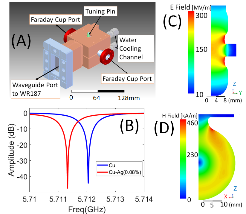
High gradient testing of accelerating structures operating at X-band is routinely conducted at SLAC National Accelerator Laboratory demonstrating peak surface electric fields greater than 350 MV/m for 1 to 1 BDR(1/pulse/meter) for RF pulse length of 85-300 ns Dolgashev et al. (2010); Laurent et al. (2011); Cahill et al. (2018). This is similar with testing of X-band structures at CERN/KEK Wu et al. (2017) and S-band work form CERN Vnuchenko et al. (2020) with both showing a maximum achievable surface electric field of 225 MV/m for a BDR of less than 1(1/pulse/meter) for the 250 ns pulse length at X-band and surface field of 220 MV/m for a BDR of less than 1 (1/pulse/meter) for the 1.2 s pulse length at S-band. Those same X-band (11.424 GHz) experiments showed that the breakdown rate correlates with peak pulse surface heating. It is hypothesized that pulsed heating results in cyclic fatigue, defect mobility and physical changes to the surface that enhance surface fields and consequently lead to breakdowns Wang et al. (2022). The accelerator cavity made for this project was designed with the goal of maximizing shunt impedance, minimizing the peak surface magnetic field at the input waveguide coupler, and reducing the pulse heating. The structure itself is a C-band version of an S-band (2.856 GHz) accelerating cavity that was designed by X. Lu et al. Lu et al. (2021) to serve as an energy modulator for =0.5 protons utilized in proton radiation therapy. The geometry was scaled down in size to increase the resonant frequency to 5.712 GHz. The two geometric differences are an increased length of the cell to ease machining requirements and the RF feed shape which was tapered due to the relatively smaller dimensions of the WR-187 waveguide compared to the WR-284 waveguide. Fig. 1a shows a mechanical modal for the cavity. The two structures were fabricated for the experiment described. One was made of pure Cu and the other one was made of a CuAg alloy with 0.08% concentration of Ag to further investigate breakdown rates in CuAg structures compared to Cu structures Cahill et al. (2018). The hypothesis, as proposed in new computational work Wang et al. (2022), was that adding a small concentration of silver is superior in copper alloy to increase resistance to the thermal and mechanical stresses during an RF pulse which could result in higher achievable fields for the CuAg structure before the onset of breakdown. Fig. 1b shows the reflection coefficient S11 that were measured during the RF cold tests of the two fabricated cavities.
Fig. 1c shows the results of Ansys electronics simulation toolkit HFSS simulations for the magnitude of the electric field plotted at the central plane of the structure. Fig. 1d shows the results of HFSS simulations for the magnitude of the magnetic field on the surfaces of the cavities and illustrates that the maximum magnetic field is located on the upper walls of the accelerating structure near the input coupler, far away from the beam iris. This is the location where the maximum of peak pulse surface heating will occur during high gradient testing. The accelerating parameters of the cavity computed with HFSS can be seen in Table 1. Compared to the S-band cavity (2.856 GHz), the scaled C-band cavity has an increased shunt, impedance Rs which is proportional to the square root of the cavity’s frequency, . Table 2 shows the Q factors and resonant frequencies extracted from the RF cold test results of the two fabricated cavities with the copper-silver cavity having a slightly higher Q-factor.
| Parameter | Cu | Cu |
|---|---|---|
| v=0.5c Proton | v=c Electron | |
| Length | 1.58 cm | |
| 0.0525 | ||
| Frequency | 5.712GHz | |
| 58 MS/m | ||
| 9762 | ||
| 10165 | ||
| 61.51 | 115.8 | |
| 62 MeV/m | 81 MeV/m | |
| 2.42 | 1.84 | |
| 1.40 | 1.07 | |
| Cold Test Results | Cu | CuAg |
|---|---|---|
| Frequency | 5.71205 GHz | 5.71133 GHz |
| 9621 | 9720 | |
| 9742 | 9805 | |
| 269 ns | 272 ns |
The high gradient testing of the two structures was performed at the C-band Engineering Research Facility in New Mexico (CERF-NM) at Los Alamos National Laboratory (LANL)Gorelov et al. (2021). The schematic and a photograph of CERF-NM are shown in Fig. 2. The facility is built around a 50 MW C-band Canon klystron that can provide up to 25 MW of RF power into the cavity at a 100 Hz repetition rate.
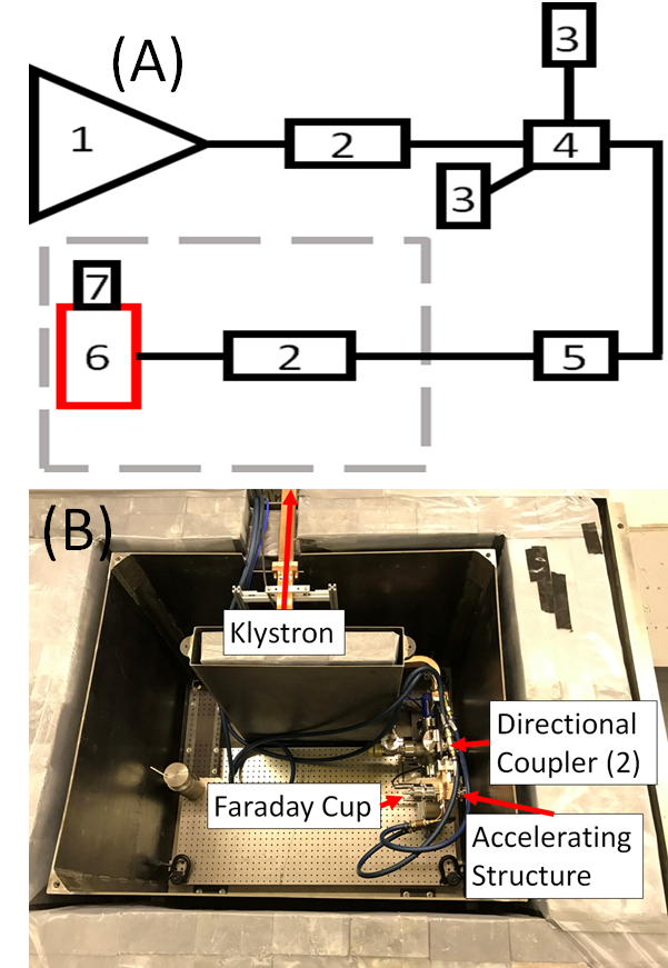
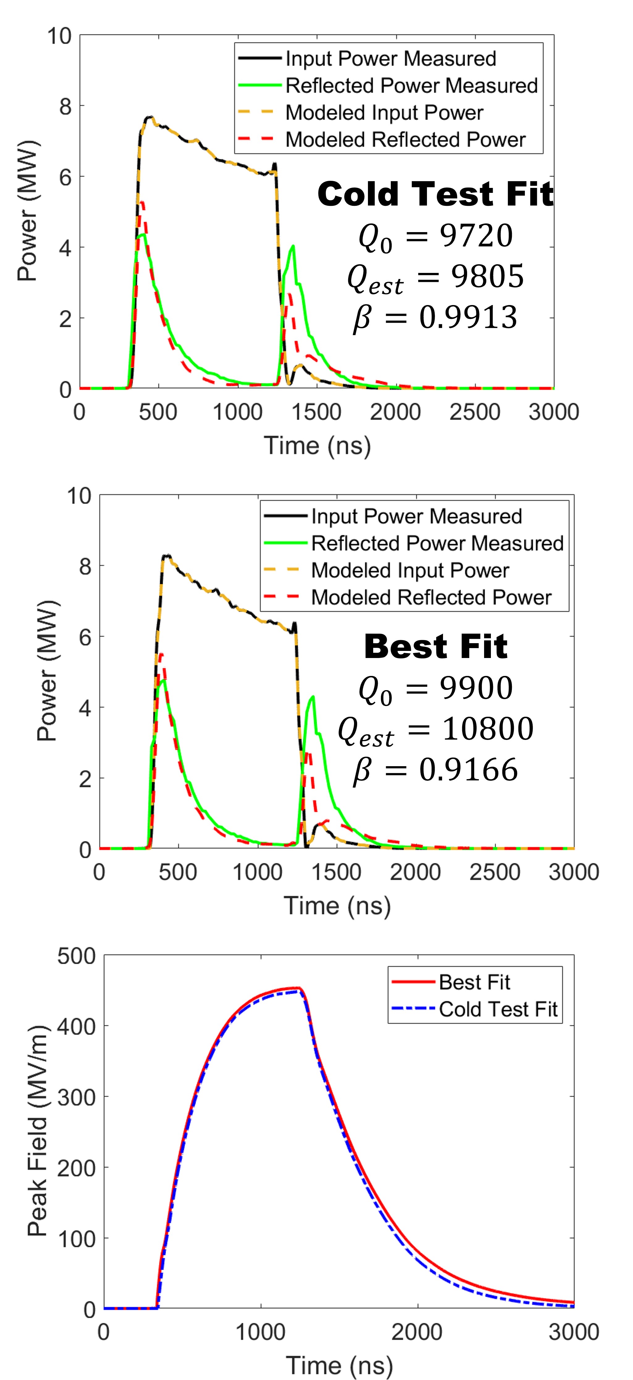
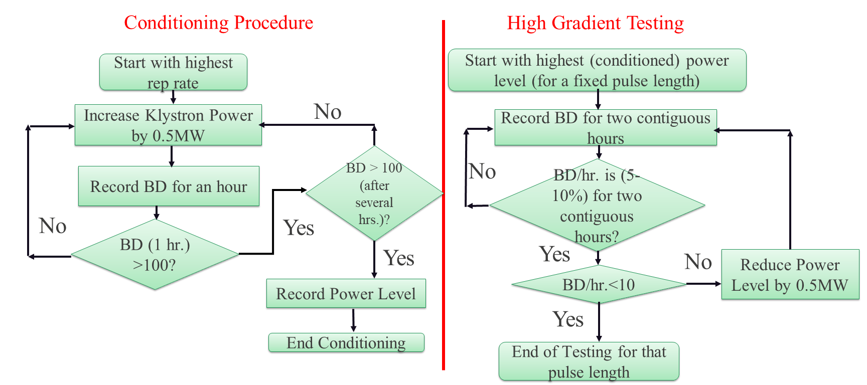
During the conditioning process, the forward and reflected pulse shapes were recorded continuously at both directional couplers shown in the schematics in Fig 2a. The dark current was monitored using a Kimball Physics FC73a Faraday cup which was mounted on the flange at the beampipe of the cavity. We developed a software package named FEbreak Schneider et al. (2021) which continuously monitored and recorded the forward and reflected traces from an analog signal of Ladybug peak power meters (LB480A). The breakdown events were identified by monitoring the Faraday cup signal with the trigger for a breakdown event set to 2.5 mV (twice the noise floor). In the end, the FEbreak software had a pulse capture efficiency of 95%, limited by the speed of the data acquisition hardware Schneider et al. (2021). This means that about than 5% of RF pulses were not captured or analyzed. To compute the gradient and peak surface fields in the cavity for the given coupled power and pulse shape, the conventional analysis for high gradient normal conducting structures was used based upon a linear equivalent circuit model assuming a constant Q-factor Wangler (1998). For this data processing we used the Ohmic and external Q-factors, and , obtained during RF cold testing. During data processing, we found that, there was a difference between the model measured reflected power reflected power. Where the model reflected power decayed faster than the measured data (see Fig. 3a) To correct the model, we used the values of =9900 and =10800 for Cu and =11120 and =11180 for CuAg which are slightly different from the RF cold testing values in Table. 2. The resulting forward and reflected pulses obtained in this “best fit model” are shown in Fig. 3b. Fig. 3c shows the peak surface electric field in the CuAg cavity calculated as a function of time for the pulse for klystron power of 14.5 MW. Fig. 3c shows that making slight adjustment to the cavity’s Q-factors used in the model had a negligible effect on the calculated peak surface fields in the cavity. Figure 5 shows the collected breakdown statistics for both Cu and Cu-Ag cavities, where the probabilities of RF breakdowns are plotted as functions of peak surface electric field (), and peak surface magnetic field () at different lengths of the RF pulses. The pulse shape for both the Cu and CuAg cavities were of similar shape. It is worth noting that the conditioning process was the same for both the Cu and CuAg cavities, as described in Fig. 4.
It was found that the structure was able to achieve remarkably high gradients with peak surface fields up to 450 MV/m for the CuAg structure and up to 360 MV/m for the pure Cu cavity with breakdown rates in the range of /pulse/meter. The 25% improvement in the maximum achievable gradient and peak surface magnetic field in the CuAg cavity as compared to the pure Cu cavity as seen in Fig. 5a agrees with what has been reported previously Cahill et al. (2018). The results in Fig. 5a indicate that the BDR data of each structure is clustered by cavity material (overlapping solid lines and overlapping dashed lines). Data was collected for both structures in approximately the same breakdown rate range (- /pulse/m). For each cavity, the same BDR at the same peak surface fields are achieved, irrespective of pulse length. This shows that the breakdown statistics are weakly dependent on pulse heating indicating that the mechanism for creating breakdowns in this structure is not dominated by RF pulse heating.
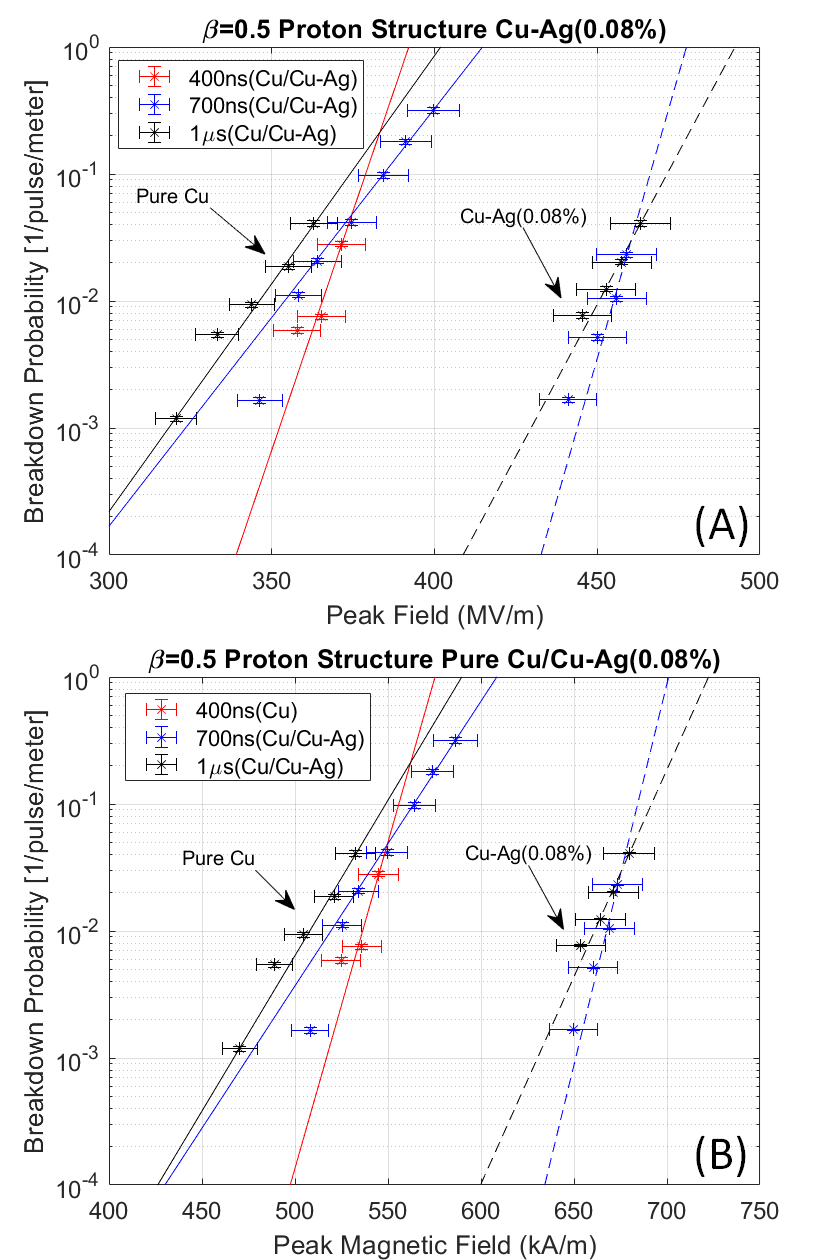
The geometry of this cavity that leads to the high shunt impedance also leads to a low magnetic field on the surface and low peak magnetic to peak electric field ratio. This is similar to an X-band structure that was reported in Dolgashev et al. (2010). The calculated peak magnetic field BDR plot, shown in Fig. 5b, is also pulse length independent, as seen and explained for the peak electric field plots in Fig. 5 (solid lines for Cu and dashed lines for CuAg).
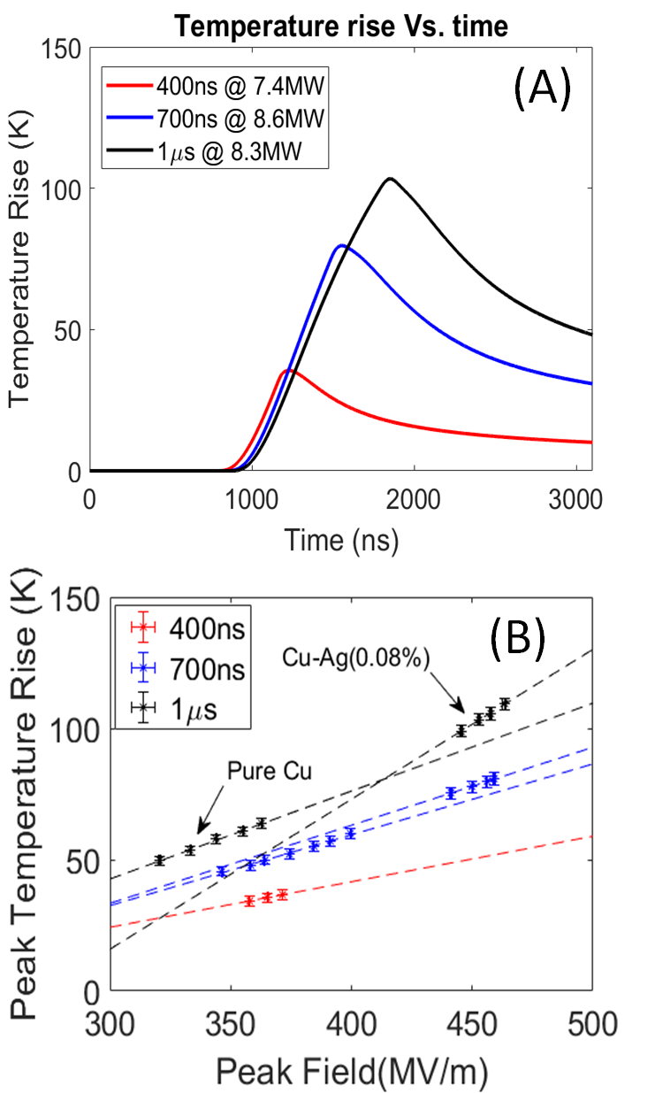
Fig. 6a shows the evolution of the peak temperature rise inside of the cavity that is due to pulse heating versus time Laurent et al. (2011)over the duration of the RF pulse. The temperature rises exponentially until it peaks immediately after the RF drive pulse is turned off. It then decays slowly to zero over the 10 ms delay between pulses that come periodically with the repetition rate of 100 Hz. In the experiment, there was no residual temperature rise between pulses see Fig. 6a. Fig. 6b shows that the CuAg structure exhibits higher temperature rise due to pulse heating than its copper counterpart because it conditioned to a higher gradient and the higher peak fields. This structure was still able to achieve higher fields than its copper counterpart because the temperature rises due to pulse heating did not have a significant impact on the breakdown statistics.
Finally, we would like to discuss why this cavity geometry could sustain much higher peak fields than previous C-band accelerating structures. In this investigation, the methodology outlined by A. Grudiev Grudiev et al. (2009) was used. In paper Grudiev et al. (2009), extensive testing of X-band accelerating structures showed that the BDR may not be dominated by pulse heating but instead the power coupling between the power flow into a field emission electron source and the RF power inside of the cavity. The authors derived a modified Poynting vector () defined:
where is the standard Poynting vector and describes the coupling coefficient between the power flow into the cavity and the power flow into the field emission electron source which is independent of the geometry and material parameters. Here is a slowly varying function of local electric field () where extensive research and field emission electron sources have found that this value saturates during a breakdown at 10 GV/m which corresponds to a =0.22. Fig 7 shows the magnitude of Sc along a cross-section of the cavity presented in this paper
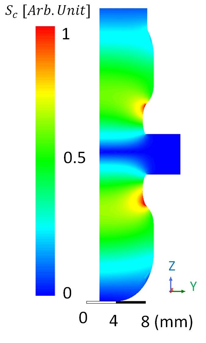
Fig. 7 shows that the maximum of is not located at the beam iris. A. Grudiev et al. showed in their experiments that a structure with a similar location of the peak of Sc was able to show an improvement in the maximum achievable peak surface electric fields when compared to the structures analyzed in their report, implying the location of Sc is a contributing factor to the maximum achievable fields in the structure. This means that the location of the maximum of the surface fields due to the change in the location of the modified Poynting vector could be another mechanism for dominating the BDR other than pulse heating.
In summary, we designed an optimal geometry to minimize pulse heating on the waveguide coupler and to minimize the peak surface electric field on the irises. This resulted in a maximum modified Poynting vector located further from the beam axis, which may have been favorable in reducing the breakdown rate. The single-cell cavity geometry was shown to sustain remarkably high peak fields in excess of 450 MV/m. This structure was able to perform with comparable fields that are achievable at X-band. This C-band structure has a larger beam iris aperture than its X-band counterpart and therefore is attractive for use in high-charge high-gradient accelerators for proton and electron machines. This experiment also confirmed that the structure made from a CuAg alloy can withstand significantly higher fields than its Cu counterpart for the same breakdown rates. In future works we will test two different methodologies for directly measuring the field to validate the fields calculated here. The first is to use direct probe measurements inside the cavity or measure the energy of dark current and the bremsstrahlung radiation due to dark current/field emission sources. These secondary measurements will also be able to determine the beam loading due to dark current/field emission effects to determine if this is a significant mechanism for determining the breakdown statistics.
Acknowledgment. LANL was supported by Los Alamos National Laboratory’s LDRD Program and Technology Evaluation and Development (TED) funds. SLAC was supported by the Department of Energy Contract No. DEAC02-76SF00515. The Authors would like to also acknowledge the excellent support and mentoring and providing excellent undergraduate and graduate students through the ASET in particular Jem Jevarjian and Sergey V. Baryshev.
Data Availability
The data that support the findings of this study are available from the corresponding author upon reasonable request.
References
- Emma et al. (2010) P. Emma, R. Akre, J. Arthur, R. Bionta, C. Bostedt, J. Bozek, A. Brachmann, P. Bucksbaum, R. Coffee, and Y. Decker, F.J.and Ding, Nat. Photonics 4, 641 (2010).
- Posen et al. (2021) S. Posen, A. Cravatta, M. Checchin, S. Aderhold, C. Adolphsen, T. Arkan, D. Bafia, A. Benwell, D. Bice, B. Chase, and C. Contreras-Martinez, arXiv preprint (2021), arXiv:2110.14580.
- Shiltsev and Zimmermann (2021) V. Shiltsev and F. Zimmermann, Reviews of Modern Physics 93, 015006 (2021).
- Nanni et al. (2022) E. A. Nanni, M. Breidenbach, C. Vernieri, S. Belomestnykh, P. Bhat, and N. et al., arXiv preprint (2022), arXiv:2203.09076.
- Bai et al. (2021) M. Bai, T. Barklow, R. Bartoldus, M. Breidenbach, P. Grenier, Z. Huang, M. Kagan, J. Lewellen, Z. Li, T. W. Markiewicz, et al., arXiv preprint arXiv:2110.15800 (2021).
- Lu et al. (2021) X. Lu, Z. Li, V. Dolgashev, G. Bowden, A. Sy, S. Tantawi, and E. A. Nanni, Review of Scientific Instruments 92, 024705 (2021).
- V. (2014) M. V., Nature 508, 133 (2014).
- Kutsaev et al. (2015) S. V. Kutsaev, R. Agustsson, A. Arodzero, L. Faillace, H. J., and Z. V., Proc. IEEE Nuclear Science Symposium and Medical Imaging Conference (2015).
- Simakov et al. (2018) E. I. Simakov, V. A. Dolgashev, and S. G. Tantawi, Nuclear Instruments and Methods in Physics Research Section A. 907, 221 (2018).
- Tantawi et al. (2020) S. Tantawi, M. Nasr, Z. Li, C. Limborg, and P. Borchard, PRAB. 23, 092001 (2020).
- Nasr et al. (2019) M. H. Nasr, P. B. Welander, Z. Li, and S. Tantawi, Proc. 10th Int. Particle Accelerator Conf. (2019), 10.18429/JACoW-IPAC2019-WEPRB090.
- Dolgashev et al. (2010) V. Dolgashev, S. Tantawi, Y. Higashi, and B. Spataro, Applied Physics Letters 97, 171501 (2010).
- Laurent et al. (2011) L. Laurent, S. Tantawi, V. Dolgashev, C. Nantista, Y. Higashi, M. Aicheler, S. Heikkinen, and W. Wuensch, PRAB. 14, 041001 (2011).
- Cahill et al. (2018) A. D. Cahill, J. B. Rosenzweig, V. A. Dolgashev, S. G. Tantawi, and S. Weathersby, PRAB. 21, 102002 (2018).
- Othman et al. (2020) M. A. Othman, J. Picard, S. Schaub, V. A. Dolgashev, S. M. Lewis, J. Neilson, A. Haase, S. Jawla, B. Spataro, R. J. Temkin, et al., Applied Physics Letters 117, 073502 (2020).
- Shao (2018) J. Shao, Springer (2018), 10.1007/978-981-10-7926-9.
- Loehl et al. (2013) F. Loehl, J. Alex, H. Blumer, M. Bopp, H. Braun, A. Citterio, U. Ellenberger, H. Fitze, H. Joehri, T. Kleeb, L. Paly, J. Raguin, L. Schulz, and R. Zennaro, Proc. FEL2013 (2013).
- Fang et al. (2016) W. Fang, Q. Gu, X. Sheng, C. Wang, D. Tong, L. Chen, S. Zhong, J. Tan, G. Lin, Z. Chen, and Z. Zhao, Nuclear Instruments and Methods in Physics Research Section A. 823, 91 (2016).
- Alesini et al. (2020) D. Alesini, M. Bellaveglia, F. Cardelli, R. Di Raddo, A. Gallo, V. Lollo, L. Piersanti, A. Variola, L. Palumbo, F. Poletto, and P. Favaron, PRAB. 23, 042001 (2020).
- Shintake (2019) T. Shintake, Proc. 10th Int. Particle Accelerator Conf. (2019), 10.18429/JACoW-IPAC2019-WEPRB090.
- Yang et al. (2010) H. Yang, S. Kim, S. Park, M. Cho, W. Namkung, J. Oh, K. Lee, and K. Chung, Proc. Linear Accelerator Conf. LINAC2010 (2010).
- Wu et al. (2017) X. Wu, J. Shi, H. Chen, J. Shao, T. Abe, T. Higo, S. Matsumoto, and W. Wuensch, PRAB. 20, 052001 (2017).
- Vnuchenko et al. (2020) A. Vnuchenko, D. Pereira, B. Martinez, S. Benedetti, N. Lasheras, M. Garlasch, A. Grudiev, G. McMonagle, S. Pitman, I. Syratchev, M. Timmins, and et al., PRAB. 23, 084801 (2020).
- Wang et al. (2022) G. Wang, E. I. Simakov, and D. Perez, App. Phys. Lett. 120, 134101 (2022).
- Gorelov et al. (2021) D. Gorelov, R. L. Fleming, S. K. Lawrence, J. W. Lewellen, M. E. Middendorf, M. E. Perez, D. Schneider, E. I. Simakov, and T. Tajiman, Proc. 12th Int. Particle Acc. Conf. (2021).
- Schneider et al. (2021) M. Schneider, R. Fleming, E. Simakov, D. Gorelov, J. Lewellen, E. Jevarjian, and S. V. Baryshev, Proc. 12th Int. Particle Acc. Conf. (2021), 10.18429/JACoW-IPAC2021-THPAB138.
- Wangler (1998) T. P. Wangler, John Wiley and Sons (1998).
- Grudiev et al. (2009) A. Grudiev, S. Calatroni, and W. Wuensch, Physical Review Special Topics-Accelerators and Beams 12, 102001 (2009).