Hyperspectral Image Denoising with Partially Orthogonal Matrix Vector Tensor Factorization
Abstract
Hyperspectral image (HSI) has some advantages over natural image for various applications due to the extra spectral information. During the acquisition, it is often contaminated by severe noises including Gaussian noise, impulse noise, deadlines, and stripes. The image quality degeneration would badly effect some applications. In this paper, we present an HSI restoration method named smooth and robust low-rank tensor recovery. Specifically, we propose a structural tensor decomposition in accordance with the linear spectral mixture model of HSI. It decomposes a tensor into sums of outer matrix-vector products, where the vectors are orthogonal due to the independence of endmember spectrums. Based on it, the global low rank tensor structure can be well exposited for HSI denoising. In addition, the 3D anisotropic total variation is used for spatial-spectral piecewise smoothness of HSI. Meanwhile, the sparse noise including impulse noise, deadlines and stripes, is detected by the -norm regularization. The Frobenius norm is used for the heavy Gaussian noise in some real-world scenarios. The alternating direction method of multipliers is adopted to solve the proposed optimization model, which simultaneously exploits the global low-rank property and the spatial–spectral smoothness of the HSI. Numerical experiments on both simulated and real data illustrate the superiority of the proposed method in comparison with the existing ones.
Index Terms:
hyperspectral image, image denoising, matrix-vector tensor factorization, total variation.I Introduction
Hyperspectral imaging uses spectrometers to collect data over hundreds of spectral bands ranging from 400nm to 2500nm in the same region. It can provide both spectral and spatial information about objects due to its numerous and continuous spectral bands. With abundant available spectral information, hyperspectral image (HSI) has been popular in a series of fields, such as remote sensing [1], food safety [2], object detection and classification [3, 4]. However, due to thermal electronics, dark current, random error of light count in the image formation, HSI is inevitably affected by severe noise during the acquisition, and it will definitely degrade the image quality. Therefore, the noise removal from HSI has become an important research area and attracted lots of attentions [5, 6, 7, 8, 9].
A number of denoising algorithms have proposed for HSI, including block matching and 3-dimensional filtering (BM3D) [10], total variational based methods [11, 12, 13], sparse representations based methods [14, 15, 16], Bayesian methods [17, 18, 19, 20]), deep learning based methods [21, 22, 23, 24, 25], and low rank based methods [26, 27, 8, 28, 29]. Among them, low rank approximation shows good performance without training, as a representative of model-based ways. It can be shown in Fig. 1, low-rank based denoising methods can be divided into matrix based ones and tensor based ones.

The matrix-based denoising unfolds the three-dimensional tensor into a matrix or treats each band independently, and uses the traditional two-dimensional image denoising methods. For example, Zhang et al. [26] divide the HSI into several fragments, rearrange these fragments into a two-dimensional matrix, and restore each fragment using the low rank matrix recovery (LRMR) method. This method is very successful in recovering HSI with mixed noise, leading to a series of denoising models based on LRMR [8, 27, 28].
However, these two-dimensional denoising algorithms are difficult to achieve optimal results since the joint spatial-spectral information of HSI is partly damaged. To address this problem, the low-rank tensor recovery (LRTR) [30] is proposed for HSI denoising [29], which simultaneously makes use of the spectral and spatial information of HSI and obtains better results than the LRMR methods. Following it, some other works using different tensor decompositions are proposed. For instance, LRTDTV [31] uses Tucker decomposition based low rank tensor recovery method [32, 33] for HSI denoising. NLR-CPTD [34] and GSLRTD [35] apply CP decomposition [36] and t-SVD [37, 38] for HSI denoising, respectively.
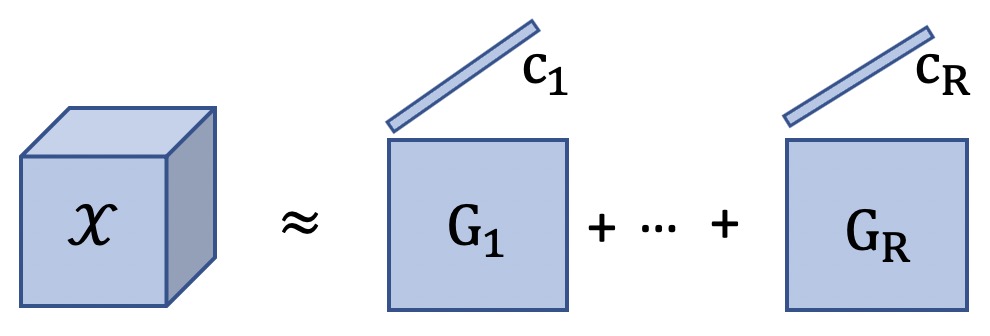
However, the commonly used three tensor decompositions cannot explicitly represent the linear spectral mixture model for HSI processing. In linear spectral mixture model, a spectrum at each pixel in the spatial domain is assumed to be a linear combination of several endmember spectra. Matrix-vector tensor factorization (MVTF) provides a more natural way to fit the linear spectral mixture model of HSI. As shown in Fig. 2, a HSI can be represented by the sum of the cross products of a endmember (vector) and its abundance map (matrix). Besides, MVTF has shown its superiority on HSI related applications, such as HSI unmixing [39] and HSI super-resolution [40]. However, in these two cases, they all ignore that the independence of endmember spectrums which is an important linear spectral mixture model prior for HSI related applications [41, 42].
In this paper, motivated by the linear spectral mixture model, we propose a structural MVTF with orthogonal vectors, and apply it to low rank based HSI denoising. The newly obtained partially orthogonal matrix vector tensor factorization can better exploit the global structure of HSI. To further enhance the recovery performance, total variation (TV) [43, 44] is used to model the piece-smooth structure of HSI. In addition, the Frobenius norm and norm terms are used to deal with Gaussian noise and impulse noise in the optimization model, respectively. The alternating direction method of multipliers (ADMM) is used to divide the optimization problem into several sub-problems. Experimental results based on HSI recovery show that the proposed method outperforms state-of-the-art ones in terms of mean peak signal to noise ratio (MPSNR), mean structural similarity index (MSSIM), and dimensionless global relative error of synthesis (ERGAS).
The main contributions of this paper can be summarized as follows:
-
1)
We develop a new low rank approximation method based on a new structural tensor factorization to model HSI. Considering that endmember spectrums are irrelevant, an orthogonality constraint is introduced on vectors (endmember spectrums) in MVTF. With this constraint, we directly minimize the ranks of abundance matrices. Compared with the method on standard MVTF, the proposed one is much faster and there is no need to set all ranks of MVTF in advance.
-
2)
A designed 3D anisotropic total variation (3DATV) term for spatial-spectral regularization is incorporated into the optimization model for low-rank tensor recovery. It can well model the local piece-wise smoothness in joint spatial-spectral domain of HSI data for denoising.
-
3)
The ADMM is used for solving the optimization model. Numerical experiments on simulated and real data illustrate the superiority of the proposed methods.
The structure of the paper is as follows. In Section 2, we give some notations used in this paper. Section 3 presents the details of the proposed hyperspectral image denoising method. The experimental results of the proposed method is given in Section 4. Section 5 summarizes the paper.
II Notations and Preliminaries
II-A Notations
In this paper, scalar, vector, matrix and tensor are denoted by lowercase letters , boldface lowercase letters and boldface capital letters , and calligraphic letters , respectively.
II-B Preliminaries on tensor computation
The norm and the Frobenius norm of a matrix are defined as:
| (1) |
and
| (2) |
respectively, where is the -th entry of .
The inner product of two tensors is defined as:
| (3) |
The cross product of two tensors and is defined as:
| (4) |
The mode- product of an -th order tensor with a matrix is a new tensor of size , which can be denoted as follows:
| (5) |
The mode- unfolding of an -th order tensor is expressed as . The mode- unfolding operator arranges the -th mode of as the row while the rest modes as the column of the mode- unfolding matrix. Mathematically, the elements of satisfy
| (6) |
where .
II-C Preliminaries on total variation
II-D Matrix-vector tensor factorization
The MVTF decomposes a tensor into the sum of several component tensors, and each component tensor can be written in the cross product form of a matrix and a vector , which can be denoted as [39]:
| (9) |
where , is the -th slice of and .
In linear spectral mixture model of hyperspectral image, can be modeled as the -th endmember spectrum, and abundance matrix represents the spatial information of -th endmember. Due to the strong spatial correlation of HSI, each abundance matrix is always low rank.
III Optimization model
As mentioned above, HSI is a third-order tensor, which has two spatial dimensions and one spectral dimension. In the data acquisition, they are inevitably polluted by noise. Considering that the observed image can be polluted by Gaussian noise and outliers, we set up the measurement model as follows:
| (10) |
where is the observed image, is the clean image, is the sparse noise or outliers, and is the Gaussian noise.
The purpose of HSI denoising is to estimate the clear hyperspectral image from the observed data contaminated by noise. In this study, we propose a novel smooth and robust low rank partially orthogonal MVTF method for HSI denoising under the consideration that endmember spectrums are irrelevant.
First, we develop a low rank partially orthogonal MVTF model for the clean HSI. It can be achieved by the following model:
| (11) |
where is the clean HSI, is the rank of -th abundance matrix , , means each abundance matrix is of low rank, and the term means endmember spectrums are uncorrelated. Next, the norm is used to separate sparse outlier from the observation. In addition, to enhance the recovery performance, the total variation term is used to exploit local smoothness structure of the HSI data.
The optimization model for this smooth and robust low rank tensor recovery (SRLRTR) for HSI denoising can be formulated as follows:
| (12) |
Since the function is nonconvex, we can use as the convex surrogate and rewrite equation (III) as follows:
| (13) |
For solving this problem, we need to introduce two auxiliary variables and , and the optimization model (III) can be rewritten into the following equivalent form:
| (14) |
The augmented Lagrangian function of the optimization model (III) is:
| (15) |
under the constraint . Therefore, we can choose to iteratively optimize one variable with the other variables fixed.
III-A Updating
Fixing other variables to update , the optimization model can be rewritten as:
| (16) |
where . The optimization problem (16) can be equivalent to
| (17) |
where . The detailed solutions of are concluded in Algorithm 1, where SVD means singular value decomposition and the soft thresholding operator of is defined as:
| (18) |
III-B Updating
III-C Updating
III-D Updating
Similarly, the optimization model (III) with respect to can be rewritten as:
| (24) |
The solution of this optimization problem can be transformed into the solution of the following linear system:
| (25) |
Considering the block circulant structure of the operator , it can be transformed into the Fourier domain and fast calculated. The fast computation of can be written as:
| (26) |
where ; and are 3D fast Fourier transform and 3D fast inverse Fourier transform, respectively.
III-E Updating
III-F Updating
By fixing all the rest variables in equation (III), we can update by the sub-problem:
| (30) |
Similarly to solving above, this optimization model can be solved by:
| (31) |
III-G Updating
Fixing the other variables in equation (III), the optimization model to update can be formulated as follows:
| (32) |
It can be easily solved by:
| (33) |
III-H Updating
The Lagrangian multiplier updating scheme can be as follows:
| (34) |
We summarize the algorithm for the SRLRTR with partially orthogonal MVTF for HSI denoising in Algorithm 2.
The convergence condition is reached when the relative error between two successive tensors is smaller than a threshold, i.e. where is the recovered image in -th iteration and is the threshold.
III-I Computational complexity analysis
The main complexity of the proposed algorithm comes from the updating of . For a hyperspectral image , the most time-consuming part is from calculating , which needs to compute the SVD of . Assuming , the computational complexity is . Therefore, the total complexity is , where is the number of iterations.
IV Experiments
In this section, two simulated datasets and two real datasets are used in the experiments to testify the effectiveness of the proposed algorithm. The reflectivity values of all pixels in the hyperspectral image are normalized between 0 and 1 before the experiment.
IV-A Datasets Descriptions
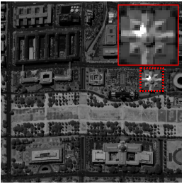
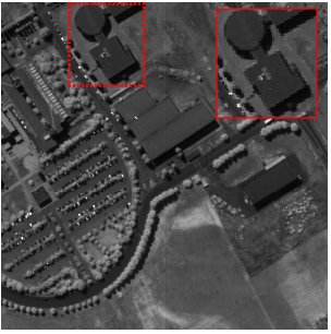
1. Washington DC Mall (WDC): The Washington DC Mall dataset111https://engineering.purdue.edu/ biehl/MultiSpec/hyperspectral.html is provided with the permission of Spectral Information Technology Application Center of Virginia. The size of each scene is . The dataset includes 210 bands in the spectral range from 400 nm to 2400 nm. We use the 191 bands by removing bands where the atmosphere is opaque. And pixels are selected from each image, forming the HSI with the size of . The false color image (R: 29, G: 19, B: 9) of WDC is shown in Fig. 3(a) .
2. Pavia University (PaviaU): This scene222https://rslab.ut.ac.ir/data is acquired by ROSIS sensor that covers the Pavia, northern Italy. The spatial size of the PaviaU is and there are 103 channels, ranging from 430 nm to 860 nm. And pixels are considered, forming the HSI with the size of . The false color image (R: 29, G: 19, B: 9) of PaviaU is shown in Fig. 3(b).
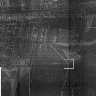
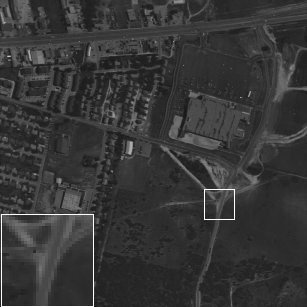
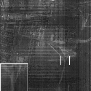
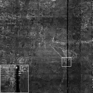
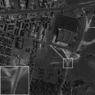
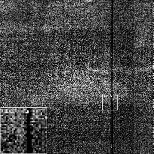
3. EO-1 Hyperion datasets (EO-1): The EO-1 Hyperion hyperspectral dataset333https://www.usgs.gov/centers/eros/science/ covers an agricultural area of the state of Indiana, USA. It contains pixels and 242 bands spanning 350nm-2600nm. After removing water absorption bands, 166 bands are retained, and pixels are selected from original scene, forming the HSI with size of . It is mainly contaminated by Gaussian noise, stripes and dead lines.The false color image (R: 2, G: 132, B: 136) of EO-1 is shown in Fig. 3(c).
4. HYDICE Urban Dataset (Urban): This scene is acquired from the real Hyperspectral Digital Imagery Collection Experiment (HYDICE) [47]. It contains pixels and there are 210 wavelengths ranging from 400 nm to 2500 nm. It is mainly contaminated by stripes and dead lines. The false color image (R: 2, G: 109, B: 207) of Urban is shown in Fig. 3(d).


| Cases | Datasets | measure indexes | 3DATVLR | RSLRNTF | LRTDTV | SSTVLRTF | NLRCPTD | SNLRSF | TVLASDA | HyRes | BM4D | SRLRTR |
| Case 1 | MPSNR (dB) | 27.12 | 19.26 | 29.01 | 20.93 | 22.13 | 22.05 | 26.65 | 20.21 | 21.15 | 29.17 | |
| MSSIM | 0.73 | 0.44 | 0.79 | 0.51 | 0.57 | 0.69 | 0.64 | 0.62 | 0.56 | 0.75 | ||
| PaviaU | ERGAS | 172.50 | 424.75 | 142.19 | 325.18 | 387.03 | 5.1E+3 | 197.91 | 384.57 | 344.21 | 141.38 | |
| CPU time (sec) | 217.04 | 723.36 | 179.96 | 729.27 | 1.8E+4 | 794.33 | 391.09 | 3.42 | 549.27 | 245.45 | ||
| MPSNR (dB) | 26.07 | 19.20 | 27.98 | 21.44 | 19.30 | 21.43 | 27.188 | 19.404 | 20.005 | 29.642 | ||
| MSSIM | 0.664 | 0.59 | 0.78 | 0.61 | 0.56 | 0.68 | 0.79 | 0.62 | 0.49 | 0.85 | ||
| WDC | ERGAS | 202.10 | 490.13 | 162.25 | 380.48 | 281.5 | 5.5E+3 | 181.64 | 480.19 | 432.21 | 141.34 | |
| CPU time (sec) | 212.72 | 631.34 | 327.80 | 1.34E+3 | 3.98E+4 | 601.76 | 332.35 | 1.98 | 1.11E+3 | 271.30 | ||
| Case 2 | MPSNR (dB) | 29.12 | 31.29 | 31.12 | 30.70 | 33.04 | 35.76 | 28.87 | 33.78 | 32.05 | 32.63 | |
| MSSIM | 0.80 | 0.819 | 0.851 | 0.746 | 0.882 | 0.924 | 0.731 | 0.886 | 0.854 | 0.823 | ||
| PaviaU | ERGAS | 139.72 | 111.53 | 108.186 | 121.21 | 90.21 | 1.06E+3 | 148.75 | 85.64 | 101.95 | 98.45 | |
| CPU time (sec) | 180.88 | 446.2 | 132.57 | 657.66 | 2.7E+4 | 2.1E+3 | 321.665 | 1.649 | 361.01 | 98.08 | ||
| MPSNR (dB) | 28.04 | 31.89 | 30.27 | 30.71 | 31.94 | 36.25 | 29.21 | 34.47 | 29.72 | 33.56 | ||
| MSSIM | 0.76 | 0.91 | 0.85 | 0.89 | 0.80 | 0.966 | 0.857 | 0.947 | 0.853 | 0.929 | ||
| WDC | ERGAS | 160.74 | 104.13 | 124.26 | 107.48 | 126.2 | 1.05E+3 | 142.42 | 78.10 | 132.68 | 87.58 | |
| CPU time (sec) | 536.77 | 888.73 | 272.92 | 1.05E+3 | 4.24E+4 | 590.02 | 431.91 | 5.541 | 683.03 | 283.91 | ||
| Case 3 | MPSNR (dB) | 32.30 | 26.06 | 33.23 | 32.733 | 26.42 | 30.35 | 32.35 | 27.44 | 24.92 | 36.75 | |
| MSSIM | 0.89 | 0.709 | 0.901 | 0.825 | 0.77 | 0.875 | 0.894 | 0.80 | 0.537 | 0.936 | ||
| PaviaU | ERGAS | 99.83 | 207.99 | 87.02 | 109.89 | 181.37 | 1.9E+3 | 103.47 | 185.12 | 253.36 | 63.12 | |
| CPU time (sec) | 167.85 | 811.507 | 129.46 | 572.934 | 2.3E+4 | 1.4E+3 | 537.47 | 3.626 | 747.35.92 | 182.65 | ||
| MPSNR (dB) | 32.23 | 26.05 | 32.96 | 33.96 | 26.04 | 29.72 | 32.91 | 26.88 | 23.81 | 37.85 | ||
| MSSIM | 0.90 | 0.82 | 0.92 | 0.93 | 0.79 | 0.90 | 0.93 | 0.85 | 0.62 | 0.97 | ||
| WDC | ERGAS | 97.85 | 208.55 | 91.81 | 85.78 | 185.3 | 2.11E+3 | 99.57 | 196.58 | 279.44 | 58.97 | |
| CPU time (sec) | 339.54 | 894.08 | 260.91 | 1.46E+3 | 3.63E+4 | 598.662 | 430.395 | 4.94 | 772.359 | 287.08 | ||
| Case 4 | MPSNR (dB) | 32.27 | 25.75 | 33.45 | 31.77 | 26.07 | 30.04 | 32.28 | 26.85 | 25.04 | 36.56 | |
| MSSIM | 0.888 | 0.693 | 0.904 | 0.819 | 0.751 | 0.879 | 0.888 | 0.849 | 0.543 | 0.934 | ||
| PaviaU | ERGAS | 100/18 | 213.79 | 87.93 | 112.32 | 187.81 | 2.10E+3 | 104.43 | 196.75 | 250.74 | 63.34 | |
| CPU time (sec) | 209.25 | 717.91 | 182.04 | 762.24 | 3.6E+4 | 790.49 | 386.89 | 4.110 | 526.23 | 211.807 | ||
| MPSNR (dB) | 32.089 | 25.83 | 32.76 | 32.99 | 25.54 | 29.62 | 32.76 | 26.85 | 23.75 | 37.181 | ||
| MSSIM | 0.897 | 0.80 | 0.91 | 0.926 | 0.76 | 0.902 | 0.936 | 0.849 | 0.617 | 0.971 | ||
| WDC | ERGAS | 101.104 | 214.84 | 93.68 | 97.85 | 202.7 | 2.14E+3 | 100.31 | 196.73 | 279.65 | 52.55 | |
| CPU time (sec) | 295.158 | 979.73 | 263.30 | 1.17E+3 | 4.31E+4 | 556.23 | 427.82 | 4.11 | 774.98 | 314.45 |


IV-B Competitive methods and measure metrics
To compare with the proposed method, we select 9 state-of-the-art algorithms and one representative wavelet denoising algorithm. The detailed descriptions are as follows:
-
•
SNLRSF [48]: a novel subspace method based on nonlocal low-rank and sparse constraints for mixed noise reduction of HSI.
-
•
NLRCPTD [34]: a method based on nonlocal low-rank regularized CP decomposition with rank determination for HSI denoising.
-
•
3DATVLR [12]: a method based on 3D anisotropic total variation and low rank constraints for mixed-noise removal of HSI.
-
•
LRTDTV [31]: a method based on total variation and low rank Tucker decomposition for HSI mixed noise removal.
-
•
RSLRNTF [49]: a novel method based on matrix-vector tensor factorization with low rank and nonnegative constrains for HSI denoising.
-
•
SSTVLRTF [50]: a method based on spatial-spectral total variation and low rank t-SVD factorization to remove mixed noise in HSI.
-
•
TVLASDA [51]: a method based on spectral difference-induced total variation and low rank approximation for HSI denoising.
-
•
HyRes [52]: a method based on sparse low-rank model, which automatically tunes parameter.
-
•
BM4D [53]: a wavelet method based on nonlocal self-similarities, which achieves great success in nature image denoising.
The parameters of the comparison algorithms are set according to the values in its corresponding literatures.
In addition, to evaluate the performance quantitatively, four metrics are used to evaluate the image denoising quality, including MPSNR, MSSI, ERGAS and CPU time. The details description are as follows:
-
•
-
•
-
•
where is number of spectral bands. is the average value of and is the recovered data. All the experiments are conducted using MatLab 2019b on a computer with 2.4 GHz Quad-Core Intel Core i5 processor and 16 GB RAM.
IV-C Experiments with simulated data
WDC and PaviaU hyperspectral images are used as simulated datasets in this experiment. To testify the proposed method, we add Gaussian noise, salt-and-pepper noise, dead line and strip noise to the simulated ground-truth datasets. Four groups of experiments are performed, and the experimental settings are as follows:
Case 1: Gaussian noise + impulse noise
In this group of experiments, the noise intensities of different bands are the same. In each frequency band, the same zero mean Gaussian noise and the same percentage of impulse noise are added. The variance of Gaussian noise is 0.2, and the percentage of impulse noise is 0.2.
Case 2: Gaussian noise +dead lines
In this group of experiments, Gaussian noise is added to each band in the same way where the noise level is equal to 0.15. In addition, a dead line is added to the spectral segment from band 41 to band 100 with the number of stripes randomly chosen from 3 to 10. The width of the stripes were randomly generated from one line to three lines.
Case 3: Gaussian noise + impulse noise+dead lines
In this group, the noise intensities of different bands are not the same. Gaussian noise with zero mean and 0.05 variance, is added to each band. The percentage of impulse noise is 0.1. The dead lines are added randomly between 41 and 100 segments, the number of stripes is selected randomly from 3 to 10, and the width ranges randomly from one line to three lines.
Case 4: Gaussian noise + impulse noise+dead lines+stripe
Based on the 3rd group of experiments, this group randomly adds stripe noise between band 101 and band 190 and the number of random stripe ranges from 20 to 40 for WDC data. For PaviaU, the dead lines are added randomly between 41 and 60 segments, the number of stripes is selected randomly from 3 to 10, and the width ranges randomly from one line to three lines. In addition, stripe noise is added between band 61 and band 100 when the number of random stripe ranges from 20 to 40.




In the proposed method, we set the parameters and for WDC and PaviaU according to the highest value of MPSNR. The detailed information is put on the discussion part.
Table I shows the results of experiments based on simulated data in terms of MPSNR, MSSIM, ERGAS and CPU time. It can be observed, in most cases, the proposed algorithm is superior to all other methods in terms of the MPSNR, MSSIM and ERGA. Specifically, our algorithm shows advantage on removing mixed Gaussian noise and impulse noise in case 1. It means that our algorithm can deal with Gaussian noise and impulse noise well. Similarly, in case 3 and case 4, when the dead line and stripe noise are added, our proposed method is also superior to existing state-of-art methods in terms of recovery quality. This may imply the superiority of the proposed method in processing mixed noise in different conditions. However, in case 2 where it contains Gaussian noise and dead lines, SNLRSF, NLRCPTD and HyRes performs better.
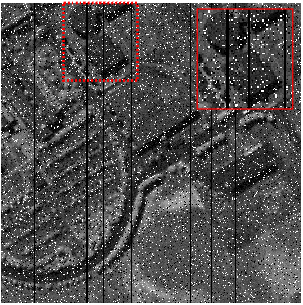
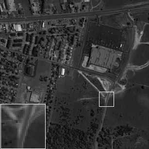
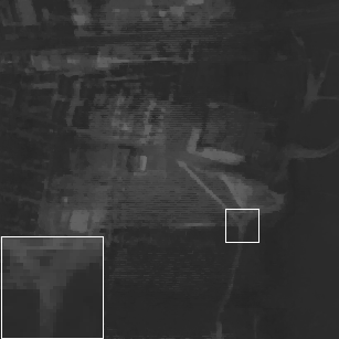
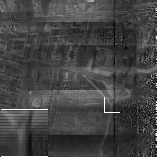
To explain the recovery results more vividly, Fig. 4 and Fig. 5 present comparative results for the 121st band of WDC HSI in case 1 and the 85th band of PaviaU HSI in case 3, respectively. Fig. 4 shows the recovered images by different methods on mixed Gaussian noise and impulse noise condition. We could observe that the resolution of recovered image in our proposed one is clearer than that of others. In addition, Fig. 5 shows the recovered images on mixed Gaussian noise, impulse noise and dead lines condition. We could see that recovered images of BM4D and RSLRTF still suffer from the dead lines noise.
To give the details of results on each spectral segment, Fig. 6 and Fig. 7 provide the PSNR of each spectral segment in case 4 for WDC and PaviaU data, respectively. In case 4, we add different kinds of noises in different spectral segments. From Fig. 6, we can see the PSNR values change smooth in the 1-41 spectral segments where Gaussian noise and impulse noise are added while the PSNR values fluctuate in 50-190 spectral segments where dead line and stripe noise are added. In addition, for each scene, the recovery performance of the proposed one is better than that of others with respect to PSNR. It indicates that the proposed method is superior in removing mixed noises. In Fig. 7, the PSNR values of the proposed method is better than the others in almost every spectral segment. It means that it can remove noise and retain the structural characteristics of HSI better.
In conclusion, the proposed method performs better in the denoising of Gaussian noise and impulse noise. In the processing of stripe noise, it can also have a leading position among the compared methods.
IV-D Experiments with real data
We choose EO-01 and Urban datasets in this experiment. Both scenes are seriously contaminated by the Gaussian noise, stripes and dead lines. In this case, we set the parameters for Urban and EO-01data.
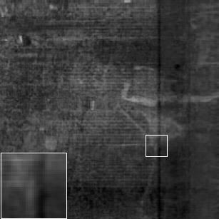
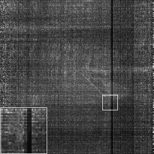
Fig. 8, Fig. 9 and Fig 10 show the denoising resulting of EO-1 hyperspectral image in bands 68, 96 and 132. It can be observed in Fig. 8, the original data are heavily contaminated by stripes noise. Our proposed algorithm can recover the HSI while local details and structural information of the HSI are preserved. However, HyRes and BM4D fail to recover the HSI in stripes noise. This is mainly because they cannot model the sparse noise. Similarly, HyRes and BM4D performs badly in Fig. 9 and Fig. 10. In addition, it can be observed that the proposed method obtains better performance in terms of image resolution.
Fig. 11, Fig. 12 and Fig. 13 show the 109th, 151st and 207th spectrum segments of Urban hyperspectral image after denoising. Fig. 11 shows that the TV based methods including LRTDTV, 3DATVLR, SSTVLRTF, TVLASDS and our proposed one have a good recovery performance on stripe noise condition. Meanwhile, the nonlocal based methods such as SNLRSF and NLRCPTD can recover the image. However, with the noise increase as shown in Fig. 12, some TV based methods including LRTDTV, 3DATVLR and SSTVLRTF are over-smoothness to recover the HSI. Instead, SNLRSF, TVLASDS and our proposed can successfully recover the clean image from the severely noise condition. Specially, as shown in Fig. 13, the scene is severely polluted by serious Gaussian noise, stripe noise and dead line, only SNLRSF, TVLASDS and our proposed method have a good recovery performance.


| Datasets | measure indexes | 3DATVLR | RSLRNTF | LRTDTV | SSTVLRTF | SNLRSF | NLRCPTD | TVLASDS | SRLRTR |
| Urban data | CPU time (sec) | 730.26 | 1.68E+3 | 558.40 | 2.82E+3 | 1.91E+3 | 6.03E+4 | 1.14E+3 | 620.03 |
| EO-1 data | CPU time (sec) | 128.38 | 574.46 | 192.97 | 1.38E+3 | 805.01 | 5.78E+4 | 247 | 163.29 |


In addition, table II shows the CPU time of our algorithm and state-of-art algorithms on real data. It is noticed that due to the poor performance of the BM4D and HyRes methods in the above experiments, we do not consider the CPU time of them for comparison. As seen in table II, 3DATVLR is the fastest one compared with others, followed by our proposed one. But the recovery performance of 3DATVLR is worse than that of SRLRTR. Meanwhile, compared with TVLASDS and SNLRSF which have a good performance on severely noisy condition, the proposed one is faster than them. It implies that the partially orthogonal MVTF method can be more efficient and suitable to explore HSI information.
V Discussion
V-A The difference between partially orthogonal MVTF and traditional MVTF
We introduce a new smooth and robust low rank partially orthogonal MVTF method for denoising of HSI. The partially orthogonal MVTF is crucial to model the clean HSI for the proposed algorithm. Compared with traditional MVTF including orthogonal MVTF [54] and nonnegative MVTF [39], the proposed one is different in two aspects.
1. The traditional orthogonal MVTF in [54] is defined as:
| (35) |
where is the SVD of and is under the unit-norm constraint. In this case, the matrices and are orthogonal. Compared with traditional orthogonal MVTF, the proposed one constrains , , resulting in partially orthogonal MVTF. The partially orthogonal MVTF has a good physical interpretation under the assumption of linear spectral mixture model for HSI, when is considered as the -th endmember spectrum, and endmember spectrums are uncorrelated.
2. The nonnegative MVTF in [39] is denoted by:
| (36) |
where is of rank , and can be factorized as with predefined rank . In HSI, the abundance matrix is low rank.
This low rank model has shown its superiority on HSI unmixing [39], where is considered as an endmember, and matrix is the corresponding abundance map. In [49], RSLRNTF uses this model for HSI denoising. In these cases, the ranks , are required to be defined in advance. In practice, accurate determination of the rank of abundance matrix of the -th endmember is impossible. Therefore, we directly minimize the rank of each abundance matrix under the assumption that endmember spectrums are irrelevant, resulting in low rank partially-orthogonal MVTF. In addition, compared with RSLRNTF [49], our proposed method shows a better recovery performance in experiments.
V-B The impact of parameters
There are four parameters in equation (III), but we only need to tune three parameters because the parameters represent the relative weights of different terms in objective function. In this case, we fix and analyze the impacts of parameters . In addition, the parameter in our algorithm has its physical meaning, which represents the number of endmembers (also called pure materials). In the following, we will take the experiments in case 4 on WDC datasets as an example and address how to choose these parameters.
1. The impact of parameters , and : For tuning the parameters , and , we set . The other three parameters are related to the weights of TV regularizer, sparse noise (i.e., impulse noise, stripes, and dead lines), and Gaussian noise, respectively. Fig. 15 shows the MPSNR values as a function with respect to and for the proposed algorithm with chosen from the set {0.01, 0.018, 0.032, 0.056, 0.1}. is selected from the set {0.0001, 0.00017, 0.00046, 0.0013, 0.0036, 0.01} and is selected from the set {0.001, 0.0028, 0.0077, 0.02, 0.05, 0.1}. It is obvious that the smaller and the larger , the value of MPSNR becomes larger. When , the proposed method can reach the peak of MPSNR.


2. The impact of parameters :

The parameter in our algorithm represents the number of endmembers. Fig. 16 shows the MPSNR value as a function of , where changes from 2 to 15 with step size 1. From it, we can see when , the value of MPSNR arrives at its peak.
VI Conclusion
In this paper, we develop a new low rank partially orthogonal MVTF model for the hyperspectral image denoising. In addition to the low rank tensor term for global data structure, a 3D tensor total variation is used to exploit the local data structure. The mixed noise is removed by different kinds of norm constraints in the optimization model too. The ADMM is used to efficiently solve the problem. Numerical experiments on HSI denoising show that our algorithm is superior to state-of-the-art algorithms in terms of recovery quality.
References
- [1] J. R. Jensen and K. Lulla, “Introductory digital image processing: a remote sensing perspective,” 1987.
- [2] A. Gowen, C. O’Donnell, P. Cullen, G. Downey, and J. Frias, “Hyperspectral imaging–an emerging process analytical tool for food quality and safety control,” Trends in Food Science & Technology, vol. 18, no. 12, pp. 590–598, 2007.
- [3] Y. Tarabalka, J. Chanussot, and J. A. Benediktsson, “Segmentation and classification of hyperspectral images using watershed transformation,” Pattern Recognition, vol. 43, no. 7, pp. 2367–2379, 2010.
- [4] D. Manolakis and G. Shaw, “Detection algorithms for hyperspectral imaging applications,” IEEE Signal Processing Magazine, vol. 19, no. 1, pp. 29–43, 2002.
- [5] Q. Yuan, L. Zhang, and H. Shen, “Hyperspectral image denoising employing a spectral–spatial adaptive total variation model,” IEEE Transactions on Geoscience and Remote Sensing, vol. 50, no. 10, pp. 3660–3677, 2012.
- [6] Y.-Q. Zhao and J. Yang, “Hyperspectral image denoising via sparse representation and low-rank constraint,” IEEE Transactions on Geoscience and Remote Sensing, vol. 53, no. 1, pp. 296–308, 2014.
- [7] B. Rasti, J. R. Sveinsson, M. O. Ulfarsson, and J. A. Benediktsson, “Hyperspectral image denoising using 3d wavelets,” in 2012 IEEE International Geoscience and Remote Sensing Symposium, pp. 1349–1352, IEEE, 2012.
- [8] W. He, H. Zhang, L. Zhang, and H. Shen, “Hyperspectral image denoising via noise-adjusted iterative low-rank matrix approximation,” IEEE Journal of Selected Topics in Applied Earth Observations and Remote Sensing, vol. 8, no. 6, pp. 3050–3061, 2015.
- [9] Q. Yuan, L. Zhang, and H. Shen, “Hyperspectral image denoising with a spatial–spectral view fusion strategy,” IEEE Transactions on Geoscience and Remote Sensing, vol. 52, no. 5, pp. 2314–2325, 2013.
- [10] K. Dabov, A. Foi, V. Katkovnik, and K. Egiazarian, “Image denoising with block-matching and 3d filtering,” in Image Processing: Algorithms and Systems, Neural Networks, and Machine Learning, vol. 6064, p. 606414, International Society for Optics and Photonics, 2006.
- [11] X. Bresson and T. F. Chan, “Fast dual minimization of the vectorial total variation norm and applications to color image processing,” Inverse Problems and Imaging, vol. 2, no. 4, pp. 455–484, 2008.
- [12] L. Sun, T. Zhan, Z. Wu, and B. Jeon, “A novel 3d anisotropic total variation regularized low rank method for hyperspectral image mixed denoising,” ISPRS International Journal of Geo-Information, vol. 7, no. 10, 2018.
- [13] H. K. Aggarwal and A. Majumdar, “Hyperspectral image denoising using spatio-spectral total variation,” IEEE Geoscience and Remote Sensing Letters, vol. 13, no. 3, pp. 442–446, 2016.
- [14] M. Elad and M. Aharon, “Image denoising via sparse and redundant representations over learned dictionaries,” IEEE Transactions on Image processing, vol. 15, no. 12, pp. 3736–3745, 2006.
- [15] J. Yan, M. Zhu, H. Liu, and Y. Liu, “Visual saliency detection via sparsity pursuit,” IEEE Signal Processing Letters, vol. 17, no. 8, pp. 739–742, 2010.
- [16] Q. Tian and S. Chen, “Cross-heterogeneous-database age estimation through correlation representation learning,” Neurocomputing, vol. 238, pp. 286–295, 2017.
- [17] M. Lebrun, A. Buades, and J.-M. Morel, “A nonlocal bayesian image denoising algorithm,” SIAM Journal on Imaging Sciences, vol. 6, no. 3, pp. 1665–1688, 2013.
- [18] L. Xu, F. Li, A. Wong, and D. A. Clausi, “Hyperspectral image denoising using a spatial–spectral monte carlo sampling approach,” IEEE Journal of Selected Topics in Applied Earth Observations and Remote Sensing, vol. 8, no. 6, pp. 3025–3038, 2015.
- [19] Y. Zheng, B. Jeon, L. Sun, J. Zhang, and H. Zhang, “Student’s t-hidden markov model for unsupervised learning using localized feature selection,” IEEE Transactions on Circuits and Systems for Video Technology, vol. 28, no. 10, pp. 2586–2598, 2018.
- [20] B. Gu, X. Sun, and V. S. Sheng, “Structural minimax probability machine,” IEEE Transactions on Neural Networks and Learning Systems, vol. 28, no. 7, pp. 1646–1656, 2017.
- [21] W. Xie and Y. Li, “Hyperspectral imagery denoising by deep learning with trainable nonlinearity function,” IEEE Geoscience and Remote Sensing Letters, vol. 14, no. 11, pp. 1963–1967, 2017.
- [22] B. Wang, X. Gu, L. Ma, and S. Yan, “Temperature error correction based on bp neural network in meteorological wireless sensor network,” in International Conference on Cloud Computing and Security, pp. 117–132, Springer, 2016.
- [23] Z. Qu, J. Keeney, S. Robitzsch, F. Zaman, and X. Wang, “Multilevel pattern mining architecture for automatic network monitoring in heterogeneous wireless communication networks,” China communications, vol. 13, no. 7, pp. 108–116, 2016.
- [24] Q. Yuan, Q. Zhang, J. Li, H. Shen, and L. Zhang, “Hyperspectral image denoising employing a spatial-spectral deep residual convolutional neural network,” IEEE Transactions on Geoscience and Remote Sensing, no. 99, pp. 1–14, 2018.
- [25] A. Maffei, J. M. Haut, M. E. Paoletti, J. Plaza, L. Bruzzone, and A. Plaza, “A single model cnn for hyperspectral image denoising,” IEEE Transactions on Geoscience and Remote Sensing, 2019.
- [26] H. Zhang, W. He, L. Zhang, H. Shen, and Q. Yuan, “Hyperspectral image restoration using low-rank matrix recovery,” IEEE Transactions on Geoscience and Remote Sensing, vol. 52, no. 8, pp. 4729–4743, 2013.
- [27] R. Zhu, M. Dong, and J.-H. Xue, “Spectral nonlocal restoration of hyperspectral images with low-rank property,” IEEE Journal of Selected Topics in Applied Earth Observations and Remote Sensing, vol. 8, no. 6, pp. 3062–3067, 2014.
- [28] W. He, Q. Yao, C. Li, N. Yokoya, and Q. Zhao, “Non-local meets global: An integrated paradigm for hyperspectral denoising,” arXiv preprint arXiv:1812.04243, 2018.
- [29] H. Fan, Y. Chen, Y. Guo, H. Zhang, and G. Kuang, “Hyperspectral image restoration using low-rank tensor recovery,” IEEE Journal of Selected Topics in Applied Earth Observations and Remote Sensing, vol. 10, no. 10, pp. 4589–4604, 2017.
- [30] H. Huang, Y. Liu, J. Liu, and C. Zhu, “Provable tensor ring completion,” Signal Processing, vol. 171, p. 107486, 2020.
- [31] Y. Wang, J. Peng, Q. Zhao, Y. Leung, X. Zhao, and D. Meng, “Hyperspectral image restoration via total variation regularized low-rank tensor decomposition,” IEEE Journal of Selected Topics in Applied Earth Observations and Remote Sensing, vol. 11, pp. 1227–1243, April 2018.
- [32] Y.-D. Kim and S. Choi, “Nonnegative tucker decomposition,” in 2007 IEEE Conference on Computer Vision and Pattern Recognition, pp. 1–8, IEEE, 2007.
- [33] Z. Long, Y. Liu, L. Chen, and C. Zhu, “Low rank tensor completion for multiway visual data,” Signal Processing, vol. 155, pp. 301–316, 2019.
- [34] J. Xue, Y. Zhao, W. Liao, and J. C.-W. Chan, “Nonlocal low-rank regularized tensor decomposition for hyperspectral image denoising,” IEEE Transactions on Geoscience and Remote Sensing, 2019.
- [35] Z. Huang, S. Li, L. Fang, H. Li, and J. A. Benediktsson, “Hyperspectral image denoising with group sparse and low-rank tensor decomposition,” IEEE Access, vol. 6, pp. 1380–1390, 2018.
- [36] T. Jiang and N. D. Sidiropoulos, “Kruskal’s permutation lemma and the identification of candecomp/parafac and bilinear models with constant modulus constraints,” IEEE Transactions on Signal Processing, vol. 52, no. 9, pp. 2625–2636, 2004.
- [37] M. E. Kilmer, K. Braman, N. Hao, and R. C. Hoover, “Third-order tensors as operators on matrices: A theoretical and computational framework with applications in imaging,” SIAM Journal on Matrix Analysis and Applications, vol. 34, no. 1, pp. 148–172, 2013.
- [38] L. Feng, Y. Liu, L. Chen, X. Zhang, and C. Zhu, “Robust block tensor principal component analysis,” Signal Processing, vol. 166, p. 107271, 2020.
- [39] Y. Qian, F. Xiong, S. Zeng, J. Zhou, and Y. Y. Tang, “Matrix-vector nonnegative tensor factorization for blind unmixing of hyperspectral imagery,” IEEE Transactions on Geoscience and Remote Sensing, vol. 55, pp. 1776–1792, March 2017.
- [40] G. Zhang, X. Fu, K. Huang, and J. Wang, “Hyperspectral super-resolution: A coupled nonnegative block-term tensor decomposition approach,” arXiv preprint arXiv:1910.10275, 2019.
- [41] N. Wang, B. Du, L. Zhang, and L. Zhang, “An abundance characteristic-based independent component analysis for hyperspectral unmixing,” IEEE Transactions on Geoscience and Remote Sensing, vol. 53, no. 1, pp. 416–428, 2014.
- [42] J. M. Nascimento and J. M. Dias, “Does independent component analysis play a role in unmixing hyperspectral data?,” IEEE Transactions on Geoscience and Remote Sensing, vol. 43, no. 1, pp. 175–187, 2005.
- [43] Y. Liu, T. Liu, J. Liu, and C. Zhu, “Smooth robust tensor principal component analysis for compressed sensing of dynamic mri,” Pattern Recognition, vol. 102, p. 107252, 2020.
- [44] Y. Liu, Z. Long, and C. Zhu, “Image completion using low tensor tree rank and total variation minimization,” IEEE Transactions on Multimedia, vol. 21, no. 2, pp. 338–350, 2018.
- [45] H. Fan, C. Li, Y. Guo, G. Kuang, and J. Ma, “Spatial-spectral total variation regularized low-rank tensor decomposition for hyperspectral image denoising [-. 5pc],” IEEE Transactions on Geoscience and Remote Sensing, no. 99, pp. 1–18, 2018.
- [46] Y. Wang, J. Peng, Q. Zhao, Y. Leung, X.-L. Zhao, and D. Meng, “Hyperspectral image restoration via total variation regularized low-rank tensor decomposition,” IEEE Journal of Selected Topics in Applied Earth Observations and Remote Sensing, vol. 11, no. 4, pp. 1227–1243, 2017.
- [47] P. A. Mitchell, “Hyperspectral digital imagery collection experiment (hydice),” in Geographic Information Systems, Photogrammetry, and Geological/Geophysical Remote Sensing, vol. 2587, pp. 70–95, International Society for Optics and Photonics, 1995.
- [48] C. Cao, J. Yu, C. Zhou, K. Hu, F. Xiao, and X. Gao, “Hyperspectral image denoising via subspace-based nonlocal low-rank and sparse factorization,” IEEE Journal of Selected Topics in Applied Earth Observations and Remote Sensing, 2019.
- [49] F. Xiong, J. Zhou, and Y. Qian, “Hyperspectral imagery denoising via reweighed sparse low-rank nonnegative tensor factorization,” in 2018 25th IEEE International Conference on Image Processing (ICIP), pp. 3219–3223, IEEE, 2018.
- [50] H. Fan, C. Li, Y. Guo, G. Kuang, and J. Ma, “Spatial-spectral total variation regularized low-rank tensor decomposition for hyperspectral image denoising,” IEEE Transactions on Geoscience and Remote Sensing, vol. 56, pp. 6196–6213, Oct 2018.
- [51] L. Sun, T. Zhan, Z. Wu, L. Xiao, and B. Jeon, “Hyperspectral mixed denoising via spectral difference-induced total variation and low-rank approximation,” Remote Sensing, vol. 10, no. 12, p. 1956, 2018.
- [52] B. Rasti, M. O. Ulfarsson, and P. Ghamisi, “Automatic hyperspectral image restoration using sparse and low-rank modeling,” IEEE Geoscience and Remote Sensing Letters, vol. 14, no. 12, pp. 2335–2339, 2017.
- [53] M. Maggioni, V. Katkovnik, K. Egiazarian, and A. Foi, “Nonlocal transform-domain filter for volumetric data denoising and reconstruction,” IEEE transactions on image processing, vol. 22, no. 1, pp. 119–133, 2012.
- [54] L. De Lathauwer, “Decompositions of a higher-order tensor in block terms—part ii: Definitions and uniqueness,” SIAM Journal on Matrix Analysis and Applications, vol. 30, no. 3, pp. 1033–1066, 2008.