Laplace Green’s Functions for Infinite Ground Planes with Local Roughness
Abstract
The Green’s functions for the Laplace equation respectively satisfying the Dirichlet and Neumann boundary conditions on the upper side of an infinite plane with a circular hole are introduced and constructed. These functions enables solution of the boundary value problems in domains where the hole is closed by any surface. This approach enables accounting for arbitrary positive and negative ground elevations inside the domain of interest, which, generally, is not possible to achieve using the regular method of images. Such problems appear in electrostatics, however, the methods developed apply to other domains where the Laplace or Poisson equations govern. Integral and series representations of the Green’s functions are provided. An efficient computational technique based on the boundary element method with fast multipole acceleration is developed. A numerical study of some benchmark problems is presented.
keywords:
Green’s Function, Laplace’s Equation , Electrostatics , infinite groundMSC:
[2010] 00-01, 99-001 Introduction
Many problems of physical interest involve fields satisfying Laplace’s equation with appropriate boundary conditions. Often, the boundaries of the domain might include surfaces of infinite extent, which for analytical convenience, are often considered to be infinite planes, so that they can be treated via the method of images. Examples include electrostatics, magnetostatics, conduction (or diffusion) from a surface at a fixed temperature (or concentration), potential flow of an ideal fluid over a body. Motivating the work reported here are the problems of electric and magnetic fields near an infinite ground, where the surface elevation departs from the plane in both the positive and negative directions, e.g., a ground with bumps and troughs.
Computation of electrostatic fields in scales where the effects of ground should be taken into account can be an important task for a number of applications, for example, for modeling fields in urban environments [1], fields generated by the transmission power lines [2], [3], and fields generated by lightning over rough ocean surface [4]. Scattering of higher frequency electromagnetic waves from rough surfaces is also of interest [5]. Note that if the wavelength is much larger than the scale of the roughness, electrostatic approximation for characterization of scattering properties of the surface is also valid.
Most of numerical methods used for such computations either neglect the presence of objects outside the computational domain or impose some boundary conditions on the domain surface (e.g., see monograph [6] and review [7]). The boundary elements can deliver solutions which provide decay of the electric potential at the infinity, while solving a boundary integral equation for the charge distribution only for the objects located inside the computational domain. It is relatively easy to account the effects of the infinite flat ground in such computations using the method of images [8]. Formally, this can be done by replacing the free space Green’s function in the boundary integral equation by the Green’s function for the semispace. This function takes zero at any point on the ground plane and so any convolution with such a Green’s function produces a solution satisfying the boundary condition on the ground. Some techniques for construction of Green’s functions for the Laplace equation in different 2D domains are developed (e.g., [9]), but they formulated in terms of complex variables and conformal mappings, which makes difficult to extend them for 3D.
In practice, the situation frequently appears to be more complicated as the ground has elevations and dips. The term “ground” can also include buildings or other construction, and can be modeled using surface boundary element meshes. In any case, such modeling is limited to the area where the solution is needed and detailed representation of the environment can be provided only inside the computational domain. The question then is how to take into account the effect of the environment outside the computational domain? One possibility is to assume periodic boundary conditions. In this case some “periodization” techniques for solution of the Laplace equation can be used (e.g., see [10]; quasi-periodic Green’s functions can be found in [11]). Another approach can be to model the environment outside some ball of radius as a flat ground, while provide a detailed meshing of all objects and the ground inside (sometimes called “locally rough surface”). In the present paper we take the latter approach.
A simple solution of the problem can be found if all points on the ground inside are located above or on the level of the flat ground at infinity (which we can denote as zero level). In this case the method of images can be applied to any objects in the domain. However, if there exist some dips, or points below the zero level the method of images is not applicable, since it requires placing the image source on the side of the ground plane opposite to the side where the actual source is located, which creates a physically unacceptable (singular) solution. In a number of papers treatment of such situation using boundary integrals for the Helmholtz equation was considered (e.g., [12], [13]). In this paper, we take a different approach and derive an analogue of the Green’s function, which accounts for the effect of infinite flat ground plane outside the computational domain, and which has no singularities besides the source location inside . This function is suitable for solution of problems with arbitrary location of boundaries inside . We implemented the method and provide some numerical examples. Note that this method can also be applied to the Helmholtz equation.
The problem described above formally reduces to solution of the Laplace equation with the Dirichlet boundary conditions on the ground. In practice, there appear also situations when the zero Neumann boundary conditions should be imposed on an infinite surface. For example, if we wish to determine underwater electric fields generated by some sources, this can be formulated as the problem with zero Neumann boundary conditions on the sea level (since the electric conductivity of the sea water is much larger than that of the air). The ocean surface can be rough, so that can be taken into account for points close to the surface, while the ocean surface can be considered as flat in the far field (also, see [14], [15], [16]). Another example of the Neumann problem appears in aerodynamics, where the effects of ground should be taken into account to determine correctly the lift force for objects flying close to the ground [17]. For flat surfaces the Neumann problem can be also solved using the method of images, which causes the same problems as for the Dirichlet problem described above. The Green’s functions for the Dirichlet and Neumann boundary conditions are closely related. In this paper we address both problems.
2 Statement of the problem
First, we consider the Dirichlet problem. Consider an infinite ground surface on which the electric potential is zero and let there be some objects on it. Let the surface be the value of the potential is given (here and below we use dimensionless equations). In the electrostatics approximation, we have the following Dirichlet problem for the Laplace equation,
| (1) | |||||
where is an infinite domain in bounded by and . The solution of this problem can be obtained using indirect boundary integral method, which represents the potential in the form of the single layer potential
| (2) |
where is the free-space Green’s function for the Laplace equation, and is the surface charge density, which can be obtained from the solution of the boundary integral equation,
| (3) |
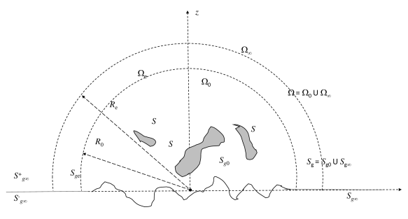
Assume further that can be modelled by a flat horizontal surface (zero elevation, ), except for a finite part near the source, and in the region in which we wish to compute the solution in details. The ground plane in this region may have arbitrary positive and negative elevations. We assume that this region is contained inside a ball of radius centered at the origin of the reference frame. It is also assumed that surface is located inside the ball. The ball partitions into domains and and into and (see Fig. 1),
| (4) | |||||
Note now that is an open surface, for which we have an “upper” side, , faced towards , and a “lower” side, faced towards . The boundary conditions need be satisfied on the upper side only. The Green’s function for the zero Dirichlet boundary conditions on can be introduced as the solution of the problem
| (5) | |||||
The solution of the Dirichlet problem (1) then can be sought in the form
| (6) |
where satisfies the boundary integral equation
| (7) |
We seek to derive analytical expressions for, and methods for computation of, the function .
Similarly, we can also get the Green’s function for the zero Neumann boundary conditions on , which can be found by solving
| (8) | |||||
Construction of this function allows one to solve the problem with mixed boundary conditions
| (9) | |||||
in form (6), where superscript should be changed to and the charge density can be determined from the boundary integral equation
| (10) | |||||
Note that functions and defined above are not unique, since the boundary condition is specified only on , while an arbitrary boundary condition can be imposed on . Depending on the type of condition on the functions may or may not satisfy the symmetry typical for Green’s functions for Dirichlet problems for closed or two-sided open surfaces with homogeneous boundary conditions [18]. Despite this non-uniqueness any solution of problems (5) and (8) delivers the Green’s function suitable for representation of solutions in form (6 ), where the charge density is determined from Eqs (7) and (10). Indeed, these relations guarantee that the solution satisfies the Laplace equation and the boundary conditions, and, so, as or are selected the solution is unique.
We also remark that, despite and can be computed for any location of the source () and evaluation () points, for boundary integral representation of the solution we only consider the case when the source is located inside the ball . Moreover, should be also located in to solve the boundary integral equations (7) and (10). As soon as the charge density is determined from these equations the values of Green’s functions at arbitrary can be used.
3 Solution
3.1 Single and double layer potentials
Solutions of the Dirichlet and Neumann problems (5) and (8) can be found using single and double layer potentials,
| (11) | |||||
Here and are the single and double layer densities, which should be found from the boundary conditions. These conditions show that
| (12) | |||||
The single and double layer potentials (11) obey the following symmetry property
| (13) |
Furthermore, we note that the single and double layer densities are related to the jumps of the potentials and their normal derivatives on the surface as
| (14) | |||||
Symmetry (13) then provides
| (15) | |||||
Boundary conditions (12) complete the solution, which can be written in the integral form
| (16) | |||||
These equations show that and enter the expression in a non-symmetric way. However, due to the symmetry of the free-space Green’s function, we have
| (17) |
Therefore, we consider only computation of the function .
3.2 Integral representations
Equations (16) already provide an integral representation of the solution. Since the domain of integration is simple, the integrals can be written in a more explicit form. Let us consider the Cartesian, cylindrical, and spherical coordinates of the points,
| (18) |
and mark the coordinates of and with subscripts ,, and the prime, respectively. Note then that for points on the surface , so
| (19) | |||||
Using the expression for the free-space Green’s function (2), we obtain from Eq. (16)
| (20) | |||||
The integrand has the following asymptotic behavior for large
| (21) |
This shows that the integral converges. The infinite domain can be truncated and we have
| (22) |
where is some cutoff radius. The second term of the asymptotic expansion in Eq. (21) does not contribute to the integral, since being integrated over the angle it produces zero. A closed form for numerical integration can be obtain by substituting the integration variable . We have then from Eq. (20)
| (23) | |||
3.3 Spherical harmonic expansions
While the integral representations of enable computation of this function for arbitrary locations of the source and evaluation points, numerical integration can be relatively expensive and more efficient way to compute the integral can be of practical interest. Equation (7) shows that to solve the boundary integral equations should be evaluated only for the case . In this case the integral can be computed using spherical harmonic expansion. For a single source located at and the following expansion of the free space Green’s function holds [19], [20]:
| (24) |
Here and are the regular and singular (at spherical basis functions
| (25) |
where are the orthonormal spherical harmonics,
| (26) | |||||
where are the associated Legendre functions defined by the Rodrigue’s formula (see [21]),
| (27) |
The derivatives of the basis functions can be expressed via the basis functions (e.g., [20])
| (28) |
where
| (29) | |||||
Thus, we have
| (30) |
For the computation of the integrals in (16) only the values for , or are needed. Using the value for [21], we have from (26)
| (31) | |||||
| (34) |
Hence,
| (35) |
This shows that
where is the Kronecker delta.
Using Eqs (24), (30), (35), and (3.3) we obtain from Eq. (16)
where
| (38) |
Here we used symmetries and . Summation in the last sum of Eq (3.3) can start at , but at this value (see Eq. (31)). Note that , but the coefficients are non-symmetric with respect to the lower indices, . Indeed, we have
| (39) |
This is due to the fact (see definition (31)). Hence, if at some and we have (and this is true as not all are zeros), then due to Eq. (39) , means . Non-symmetry of the coefficients also shows that is non-symmetric, since the spherical harmonics form a complete orthogonal basis on a sphere (and are proportional to them).
4 Numerical methods
4.1 Dimensionless forms
Since the Laplace equation does not have intrinsic length scales, we have for arbitrary (see Eqs (23) and (3.3))
| (40) | |||||
where is the dimensionless function, which does not depend on parameter , which is seen from its integral representation. We put an extra argument to the dimensional function to show its parametric dependence on . The series for and converge for and located inside the unit ball.
4.2 Improvement of convergence
Our numerical experiments show that computation of the kernel function via double integral representation (40) provides accurate results, but such computations are somehow slow as they require evaluation of integrals for every pair and . On the other hand, recursive computations of the spherical basis functions provide a fast procedure.
For practical use all infinite series should be truncated with some truncation number ( ), which should be selected based on the error bounds. The radius of convergence of series (40) is both, with respect to and . This means that for points in located closely to the boundary with domain the truncation number can be large, which may reduce the efficiency of computations.
Several tricks can be proposed to improve the convergence. First, one can simply implement integral and series representations of the kernel and switch between algorithms based on the values and . Second, we can effectively reduce the size of the domain, where should be computed. This is based on the observation that for the evaluation points located on plane we have from Eqs (25), (26), (31), and (38)
| (41) |
due to . Hence,
| (42) |
Also, relation (42) follows from the integral representation (20).
Consider now an extended computational domain, which can be denoted as , and which includes and the part of located between the concentric spheres of radii and Respectively, denotes the part of ground surface in domain (see Fig. 1). All formulae derived hold in case if we replace with , with and with . So, instead of Eq. (6) we should have
| (43) |
The charge density can be determined from the boundary conditions
| (46) | |||||
The latter holds since for . Hence, both for the field computations (43) and determination of the charge density only values of for are needed. On the other hand, should be computed for with a notice that for we have We developed an efficient recursive procedure for such computations described in the next subsection.
4.3 Computations for the ground points on the extended domain
So, the problem for use of the extended domain is to compute function represented in Eq. (40) by infinite series at , at where . Integral representation of can be obtained by substituting of Eq. (30) into integral (16). In the dimensionless form we have
| (47) |
So,
| (48) |
| (49) | |||||
These functions can be expressed via the complete elliptic integrals of the first and second kinds, and (see[21]), and recursive relations (to shorten notation we drop the argument for functions and )
| (50) | |||||
| (51) | |||||
| (52) | |||||
| (53) | |||||
| (54) | |||||
| (55) | |||||
| (56) |
Appendix A describes how these relations are obtained. We remark that because when is an even number, to obtain in Eq. (48) we need to compute functions only at odd values of , which is reflected in the above recurrences. The recurrence for works in layers in subscript . So, first, we obtain for all needed, then , and so on until at maximum needed. For truncation number , we have max, max. As recurrence (52) show that the maximum computed at should be , while at it should be . It is also remarkable that recurrence (50) can be used first at , which provides the value of , and then applied for other in the sequence.
4.4 Boundary elements
Equation (46) can be solved using the method of moments (MoM) or collocation boundary element methods (BEM). In the present study we use the BEM. The surface is discretized by triangular elements, the integrals involving Green’s function are computed analytically assuming that the charge density is constant over the elements (constant panel approximation). The integrals involving kernel were computed using center panel quadrature,
| (57) |
where is the mean value of the charge density, while and are the area and the centroid of triangle . In the standard BEM realization the integrals over the kernels with Green’s functions were computed analytically.
| (58) |
| (59) | |||||
where is the normal to triangle directed into the computational domain.
4.5 Fast multipole method
For large problems the BEM can be accelerated using the fast multipole method (FMM) (e.g., [22]). As shown, the kernel is either zero or can be factored for any pair of points inside the computational domain of radius . This shows that boundary integral equation (46) can be written as
| (60) | |||
| (63) |
where the infinite sum over is truncated. The first integral in the left hand side can be computed using the FMM with the free space Green’s function. In our implementation, we used some nearfield radius . So, for pairs of points located closer than the integrals over triangles were computed analytically using Eqs (58) and (59), while for larger distances the integrals were computed using center point approximation, similarly to (57).
The most important feature of the global kernel factorization is that the number of operations to compute the matrix-vector product for the kernel is , not , since all integrals over can be computed independently from the evaluation points ( is the number of boundary elements). So, computation of this sum has the asymptotic complexity consistent with the FMM, and the method can be applied for solution of large problems, where the overall linear system is solved iteratively.
4.6 Real basis functions
5 Complexity and optimization
5.1 Kernel computations
Assume there are sources and receivers in domain . Truncation of the series representation of for with truncation number produces errors . If there are sources in the extended domain then the computational cost for factored can be estimated as
| (68) |
where the first term is the cost to compute functions , the second term is the cost to compute functions for using series (66), and the third term is the cost to compute functions for using Eq. (67) and recursions (50)-(56) for . Assume now that the sources are uniformly distributed in domain , with the density points per surface area. In this case . For prescribed accuracy we have , which brings the following expression for the computational cost
| (69) |
where , and are some asymptotic constants.
Considering as a function of , we can see that
| (70) |
The term in the square brackets has a single zero at and is positive at
| (71) |
So, function grows monotonically at for any values of and The function can grow or decay at depending on and . Note now, that corresponds to
| (72) |
This means, that being considered as a function of decays in the region and may continue to decay or start to grow at . It is remarkable, that does not depend on , so for computations using the factored kernel the optimal radius of the extended domain should be always larger than . Also, it can be noted that the values of are rather small. For example, at we have , which means that should be sufficient to achieve the required accuracy at . This also shows that at large enough and computational costs in Eq.(69) are much smaller than that for kernel computations using the integral representation, which formally is with the asymptotic constant that can be substantially large as the cost of numerical quadrature also depends on the required accuracy.
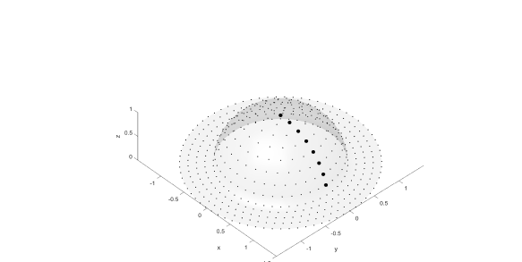
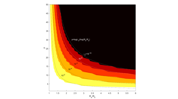
To validate these findings we conducted some numerical experiments. First, we did error estimates of the factored solutions using comparisons with the error-controlled integral computations (Matlab integral2 function). For this purpose due to the symmetry of the problem, all receivers can be placed on the intersection of a unit hemisphere (“bump”) with plane . On the other hand, the sources can be distributed over the hemisphere surface and in the extension of the domain (see Fig. 2). Figure 3 shows the relative -norm errors, ,
| (73) |
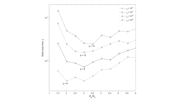
where is the computed and is the reference solution for all computed source-receiver pairs as the filled contours in plane . It is seen that the boundaries of the regions agree well with the error approximation . Figure 4 is computed by finding for each the smallest at which the computed is smaller than the prescribed accuracy and plotting the wall-clock time required for kernel computation via factorization. It is seen that dependences computed at different prescribed have global minima in the range at . This agrees well with the theoretical estimates provided above. Note that non-monotonous character of the curves shown on this plot is due to discrete change of parameters and and thresholding (the curves show the prescribed error curves, not the actual errors, which can be close to or several times smaller than the prescribed errors). Also, this figure shows that optimization of the extended domain size can speed up computations several times.
5.2 Optimization of the Boundary Element Solution
The extension of the domain can substantially impact the complexity and memory requirements of the BEM and it is preferable not to extend the domain too much. Assume that and , . In this case, , the first term in Eq. (69) can be neglected, and we obtain
| (74) |
Here we assumed that the density of sampling of the domain extension is the same as the density of sampling of surface of area , means . The last term in the parentheses then can be neglected at , due to , and assumed
There are different versions of the BEM including those using iterative methods and the FMM, which have different computational costs, e.g., , , for problems of size So, the cost of the BEM with the extended domain kernel computing at can be estimated as
Here is some asymptotic constant related to the BEM cost. While it appears that the cost of the last term is much smaller than the cost of the first term, we retained it, as the first term is constant, while the last term reflects the main mechanism of increase of the cost at the increasing . Indeed, taking derivative of this expression we can see that has a global minimum,
| (76) | |||||
This shows that, indeed, at and and fixed other parameters the optimal size of the extension, , turns to zero. For the regular BEM with exact solvers we have . However, when is not very high the cost of the FMM can be limited by the cost of boundary integral computing, in which case . Also, this can be achieved with iterative solvers. In the case of the FMM acceleration or close to 1. In this case, should not depend on , and the only reason why can be related to large values of asymptotic constant . Usually, this is true for the FMM.
6 BEM computing
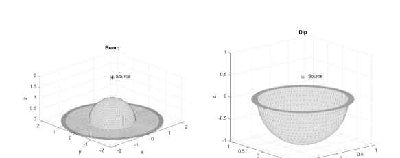
For illustrations of the kernel can be used with the boundary elements we consider the following benchmark problems for validation. We assumed that the ground elevation is the following function of and ,
| (77) |
Here the sign “+” corresponds to a “bump”, while the sign “-” corresponds to a “dip”. Assume then that the electric field is generated by a monopole source (charge) of unit intensity located at , and the domain is bounded by a sphere of radius () centered at the origin for the “bump” and , for the “dip” (). Figure 5 shows the meshes used in computations.
For validation purposes, the solution of the problem for the bump can be found analytically using the method of images. In this case, the image of the bump is a hemisphere, which together with the “image” bump forms a sphere of radius 1 on which the potential is zero. The image source of negative intensity (sink) is located at , and we have the following expression for the potential
| (78) |
where and are the images of and with respect to the sphere. We are not aware about analytical solutions for the case of “dip” for which the method of images cannot be applied.
The boundary integral solution of the problem can be represented in the form
| (79) |
where the charge density can be found from
| (80) |
In the case of “bump” we computed and compared four solutions: 1) analytical; 2) regular BEM using method of images (two symmetric sources and a sphere) (“BEMimage”); 3) regular BEM, where the domain ground plane was simply truncated and the effect of the infinite plane ignored (“BEM”); 4) BEM with the kernel accounting for the infinite plane as described by Eqs (79) and (80) (“BEMinf”). In case of “dip” only solutions 3) and 4) were computed. In all cases we varied . The truncation number for “BEMinf” method was selected based on the theoretical estimate, , where the prescribed error varied in range .
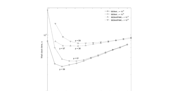
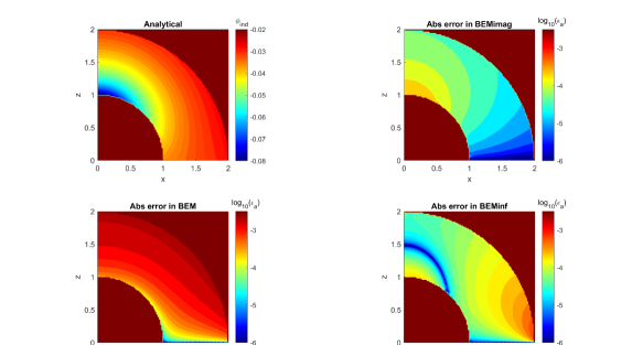
Figure 6 illustrates the effect of the domain extension on the performance for different prescribed accuracies and the BEM complexities for the “bump” case (). Note that here the FMM accelerated BEM was implemented in the way that the boundary integrals were computed within some cutoff radius of the evaluation point using Matlab, while the FMM procedure was executed in the form of a high performance library, so the cost of the FMM BEM is mainly determined by the Matlab integral computations, which is consistent with the kernel evaluation also implemented in Matlab. Also, in the regular BEM the solution time was much smaller than the integral computation time. So, the methods shown can be characterized as for the BEM and for the BEM/FMM. It is seen that the curves form minima (sometimes a few local minima), at relatively low . According to the theory (see Eq. (76)), increasing the prescribed accuracy results in an increase of the optimal , which is seen on the figure. For substantially larger than the cost of kernel computation becomes negligible in comparison to the BEM costs, and the curves computed for different become close to each other.
Figure 7 shows the analytical solution (78) (the induced part, ), and the absolute errors in the computational domain obtained using different methods of solution for the “bump” case, , , , and , where and are the number of boundary elements in and , respectively. The numerical solution using image sources is the most accurate and its relative -norm error is . The BEMinf shows error (at the prescribed accuracy ) while the BEM shows , which is one order of magnitude larger. This figure shows also different error distributions for different methods inside the computational domain.
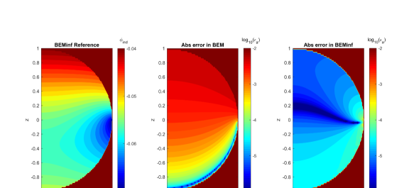
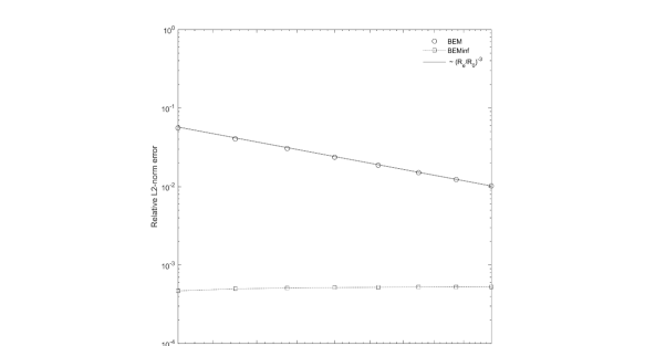
Figure 8 shows the reference solution for the “dip” case and the absolute errors in the computational domain obtained using BEMinf and the regular BEM, , , , and . The reference solution was computed using BEMinf with parameters , , and and prescribed . The BEMinf shows error (at the prescribed accuracy ) while the BEM shows , which is two orders of magnitude larger. Similarly to the case of “bump” one can observe different error distributions for the BEMinf and the BEM. Similarly to the case of “bump” the largest BEMinf errors are observed near the edge of domain coinciding with the ground plane.
Figure 9 plots for the “dip” case as a function of parameter . It is seen that the error is practically constant for BEMinf, while it decays inversely proportionally to the volume of the computational domain for the regular BEM. It is clear then that the results of BEMinf can be obtained by simple extension of the computational domain, but for substantially higher computational costs. For example, to achieve two orders of magnitude in error reduction one should have , which may require one order of magnitude increase in the number of boundary elements and increase the computational costs 10-1000 times, based on the solution method used (scaled as , ).
7 Conclusion
We introduced analogues of Green’s function for an infinite plane with a circular hole. We also proposed and tested efficient methods for computing of these functions, which may have broad applications to model infinite ground or ocean surfaces in the problems requiring Laplace equation solvers. While such functions can be expressed in the forms of finite integrals, their computation can be costly. However, a computationally efficient factorization of these functions can be done, which drastically reduces the computational costs, and, in fact, creates rather small overheads to the problems, which simply ignore the existence of ground outside the computational domain. Also, we conducted some optimization study and provided actual boundary element computations for some benchmark problems. The study shows that the accuracy of the solution using the analogues of Green’s function improves substantially compared to a simple domain truncation, which also can become computationally costly for improved accuracy computations.
8 Acknowledgements
This work is supported by Cooperative Research Agreement (W911NF1420118) between the University of Maryland and the Army Research Laboratory, with David Hull, Ross Adelman and Steven Vinci as Technical monitors.
9 References
References
- [1] R. Adelman, Extremely large, wide-area power-line models, Supercomputing 2017, https://sc17.supercomputing.org/SC17%20Archive/tech_poster/poster_files/post251s2-file3.pdf.
- [2] M. D’Amore, M. S. Sarto, Simulation models of a dissipative transmission line above a lossy ground for a wide-frequency range. I. Single conductor configuration, IEEE Trans. Electromag. Compat. 38(2) (1996) 127-138. https://doi.org/10.1109/15.494615.
- [3] M. Trlep, A. Hamler, M. Jesenik, B. Stumberger, Electric field distribution under transmission lines dependent on ground surface, IEEE Trans. Mag. 45(3) (2009) 1748-1751. https://doi.org/10.1109/TMAG.2009.2012806.
- [4] Q. Zhang, J. Yang, D. Li, Z. Wang, Propagation effects of a fractal rough ocean surface on the vertical electric field generated by lightning return strokes, J. Electrostat. 70(1)(2012) 54-59. https://doi.org/10.1016/j.elstat.2011.10.003.
- [5] K. S. Chen, T.-D. Wu, L. Tsang, Q. Li, J. Shi, A.K. Fung, Emission of rough surfaces calculated by the integral equation method with comparison to three-dimensional moment method simulations, IEEE Trans. Geo. Rem. Sensing 41(1) (2003) 90-101. https://doi.org/10.1109/TGRS.2002.807587.
- [6] D. Givoli, Numerical Methods for Problems in Infinite Domains, Elsevier, Amsterdam, 1992.
- [7] S.V. Tsynkov, Numerical solution of problems on unbounded domains. A review, Appl. Num. Math. 27(4) (1998) 465-532. https://doi.org/10.1016/S0168-9274(98)00025-7.
- [8] J.D. Jackson, Classical Electrodynamics, third ed., John Wiley and Sons, New York, 1998.
- [9] D. Crowdy, J. Marshall, Green’s functions for Laplace’s equation in multiply connected domains, IMA J. Appl. Math. 72 (2007) 278-301. https://doi.org/10.1093/imamat/hxm007.
- [10] N.A. Gumerov and R. Duraiswami, A method to compute periodic sums, J. Comput. Phys. 272 (2014) 307-326. https://doi.org/10.1016/j.jcp.2014.04.039.
- [11] A. Moroz, Quasi-periodic Green’s functions of the Helmholtz and Laplace equations, J. Phys. A: Math. Gen. 39(36) (2006) 11247. https://doi.org/10.1088%2F0305-4470%2F39%2F36%2F009.
- [12] G. Bao, J. Lin, Near-field imaging of the surface displacement on an infinite ground plane, Inverse Problems & Imaging, 7(2) (2013), 377-396. https:/doi.org/10.3934/ipi.2013.7.377.
- [13] S. N. Chandler-Wilde, E. Heinemeyer, R. Potthast, Acoustic scattering by mildly rough unbounded surfaces in three dimensions, SIAM J. Appl. Math. 66 (2006) 1002–1026. https://doi.org/10.1137/050635262.
- [14] J.J. Holmes, Past, present, and future of underwater sensor arrays to measure the electromagnetic field signatures of naval vessels, Marine Tech. Soc. J. 49(6) (2015) 123-133. https://doi.org/10.4031/MTSJ.49.6.1.
- [15] R. Yue, P. Hu, J. Zhang, The influence of the seawater and seabed interface on the underwater low frequency electromagnetic field signatures, 2016 IEEE/OES China Ocean Acoustics (COA), Harbin (2016) 1-7. https://doi.org/10.1109/COA.2016.7535694.
- [16] X. Wang, Q. Xu, J. Zhang, Simulating underwater electric field signal of ship using the boundary element method, Progress In Electromag. Res. M 76 (2018) 43-54. https:/doi.org/10.2528/PIERM18092706.
- [17] K.V. Rozhdestvensky, Aerodynamics of a Lifting System in Extreme Ground Effect, Springer, Berlin-Heidelberg, 2000.
- [18] D. G. Duffy, Green’s Functions with Applications, CRC Press, Taylor & Francis Group, FL, 2015.
- [19] P.M. Morse, H. Feshbach, Methods of Theoretical Physics, McGraw-Hill, NY, 1953.
- [20] N.A. Gumerov, R. Duraiswamin, Comparison of the efficiency of translation operators used in the fast multipole method for the 3D Laplace equation, UMIACS TR 2005-09, Also issued as Computer Science Technical Report CS-TR-# 4701, University of Maryland, College Park, 2005. https://drum.lib.umd.edu/bitstream/handle/1903/3023/LaplaceTranslation_CSTR_4701.pdf.
- [21] M. Abramowitz, I.A. Stegun, Handbook of Mathematical Functions, National Bureau of Standards, Washington D.C., 1972.
- [22] R. Adelman, N.A Gumerov, and R. Duraiswami, FMM/GPU-accelerated boundary element method for computational magnetics and electrostatics, IEEE Trans. Mag. 53(12) (2017), 7002311. https://doi.org/10.1109/TMAG.2017.2725951.
- [23] N.A. Gumerov and R. Duraiswami, Fast multipole methods on graphics processors, J. Comput. Phys. 227 (2008), 8290-8313. https://doi.org/10.1016/j.jcp.2008.05.023.
Appendix A Derivation of Recurrence Relations
Recurrence (52) can be derived by comparing two representations of integral
which can be checked using definition of (49), and integration by parts:
Equation (53) can be checked directly using integral representation of and definition of
To obtain recurrence (54) we note the following transformation
| (83) | |||
Using this expression, we obtain
It is not difficult to see that Eq. (54) follows from this expression.
Functions and can be expressed immediately via complete elliptic integrals. Indeed, we have
So,
| (86) |
where and are defined by Eq. (56). The Landen transformation of elliptic functions [21] shows that
| (87) | |||||
Substituting this into Eq. (86) and using the value of from Eq. (A) we obtain Eq. (55).