Light-induced electronic polarization in antiferromagnetic Cr2O3
In a solid, the electronic subsystem can exhibit incipient order with lower point group symmetry than the crystal lattice. External fields that couple to electronic order parameters have rarely been investigated, however, despite their potential importance to inducing exotic effects. Here, we show that when inversion symmetry is broken by the antiferromagnetic (AFM) order in Cr2O3, transmitting a linearly polarized light pulse through the crystal gives rise to an in-plane rotational symmetry breaking (from to ) via optical rectification. Using interferometric time-resolved second harmonic generation, we show that the ultrafast timescale of the symmetry reduction is indicative of a purely electronic response; the underlying spin and crystal structures remain unaffected. The symmetry-broken state exhibits a dipole moment, and its polar axis can be controlled with the incident light. Our results establish a coherent nonlinear optical protocol by which to break electronic symmetries and produce unconventional electronic effects in solids.
Neumann’s principle, formulated in 1885, stipulates that the physical properties of a perfect crystal must possess at least the point group symmetries of the underlying crystal symmetry1 . It serves as a cornerstone for interpreting experiments on crystalline matter. In recent years, however, this paradigm has been increasingly questioned. Electronic nematics, which are characterized by a lowering of rotational symmetry that is not simply a consequence of reduced lattice symmetry, challenge this framework kivelson . Experiments on electronic nematics illustrate that the symmetry of the electronic subsystem can potentially be decoupled from that of the lattice eisenstein ; feldman ; mackenzie ; harter ; bozovic ; fisher ; bozovic2 ; moll ; matsuda .
An outstanding related question is whether external fields can be found that break point group symmetries of only the electronic subsystem TaAs ; TaAsprl . In the current experimental landscape, it is difficult to disentangle the extent to which the electrons or ions respond to static fields like strain, pressure or electric fields. However, ultrafast light pulses can potentially overcome this roadblock.
One method to isolate the electronic subsystem is to use a Floquet engineering protocol, where an ultrashort light pulse is shone below the electronic gap to avoid absorption and heating Floquet ; nonlinearFloquet ; shirley . The electrons can then be driven coherently by the light’s oscillating fields and potentially be decoupled from the lattice. To date, Floquet engineering has been primarily used in two ways. First, it has been used to break the rotational symmetry of the spin subsystem through the inverse Faraday or inverse Cotton-Mouton effect InverseFaraday ; InverseFaradayNiO ; InverseCMENiO ; InverseCM . Second, the electronic subsystem has been manipulated without a change in symmetry by engineering energy level shifts through the AC Stark and/or Bloch-Siegert effects MnPS3 ; WS2 ; WS22 ; Yihua ; Fahad ; mciver . So far, engineering the rotational symmetry of the electronic subsystem has not been shown; an electronic counterpart to the inverse Faraday effect remains to be discovered.
In this work, by shining an ultrashort light pulse through a noncentrosymmetric antiferromagnet, we show that optical rectification can induce a quasi-DC response that selectively breaks the in-plane rotational symmetry of the electronic subsystem. Optical rectification is a nonlinear process whereby light’s oscillating electric field brings about a quasi-DC electric dipole moment Boyd ; OR ; Kaplan . To leading order, the induced dipole moment is given by:
| (1) |
where (=1, 2) is the electric field vector of the incident light, is the second-order nonlinear susceptibility tensor that describes optical rectification, and the frequency of the rectified response is given by with and within the energy spread of the light pulse. Crucially, when light pulses shorter than the typical structural response timescales are used to generate a rectified dipole moment, one can distinguish between a structural and an electronic response via the system’s relaxation dynamics.
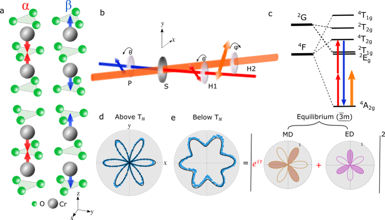
To observe the induced symmetry breaking, we probe the system with rotational anisotropy second harmonic generation (RA-SHG), a technique sensitive to electronic symmetries SHGastool . In our experimental configuration, both the incident fundamental and detected second harmonic light beams are polarized along the same direction (Fig. 1(b)). As a model compound, we select the prototypical linear magnetoelectric Cr2O3 because, as we describe below, interference of the electric and magnetic dipole second harmonic radiation allows for high-sensitivity detection of broken point group symmetries FiebigSHG ; topography ; timeCr2O3 ; timeCr2O32 ; timeCr2O3wall .
At equilibrium, Cr2O3 undergoes an antiferromagntic transition at 307 K. Above , Cr2O3 possesses (D3d) point group symmetry. Electric dipole SHG is forbidden in this state due to the presence of inversion symmetry. However, when the second harmonic energy is tuned to a Cr - electronic transition () at 2.1 eV (590 nm), we observe resonant magnetic dipole SHG (Fig. 1(c)-(d)) FiebigSHG . As shown in Fig. 1(d), the RA pattern is consistent with the threefold symmetry of the crystal when the probe light propagates along the out-of-plane direction (and is polarized in-plane).
Below , Cr2O3 orders antiferromagnetically with the four Cr spins in the unit cell alternating in an up and down sequence along the rhombohedral optical axis (Fig. 1(a)). This spin structure breaks inversion symmetry, and the magnetic point group becomes Birss . Electric dipole SHG is then allowed (through the spin-orbit interaction) and interferes with the pre-existing magnetic dipole signal ME0 ; ME1 ; ME2 . Due to the presence of both magnetic and electric dipole signals, the nodes present in the RA pattern above are lifted below (Fig. 1(e)). That the nodes are lifted implies a relative phase (not zero or 180∘) between the magnetic and electric dipole SHG amplitudes at the probed wavelength. The RA pattern below can be fit with a simple function that includes electric and magnetic dipole radiation (Fig. 1(e)) FiebigSHG :
| (2) |
where is the real-valued in-plane electric/magnetic dipole second harmonic susceptibility, the depends on the AFM domain state and denotes the relative phase between magnetic and electric dipole second harmonic radiation (see Supplementary Note I). Here, is the frequency of the probe light and represents the polarization angle of the incident and detected light with respect to the sample’s -axis (Fig. 1 (b)). Below , the electric dipole SHG susceptibility, , is proportional to the AFM order parameter, L FiebigSHG . Thus, differs in sign between the two AFM domain states, which we denote and (Fig. 1(a)) FiebigSHG ; topography . In Eq. 2, it is also important to note that depends sensitively on the second harmonic energy (Supplementary Note VI). At the 2.1 eV second harmonic energy used here, 85∘ and the two domain states exhibit almost identical RA patterns (left panels of Fig. 2(b) and (d)) Cr2O3book . This equivalence can be understood by noting that cross terms in Eq. 2 vanish when which eliminates the contrast between domain states. The interference between the electric and magnetic dipole SHG equips the crystal with an inherent phase sensitivity, which is key to observing the large symmetry-breaking response that we now demonstrate (Supplementary Note VI).
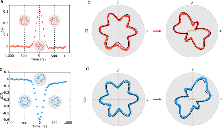
We now move on to pump the Cr2O3 crystal with 1.2 eV (1030 nm) light pulses with fluences up to 20 mJ/cm2. The pump polarization is aligned along the -axis, as indicated with the double headed arrows in the right panels of Fig. 2(b) and (d). The wavelength of the pump light lies in the transparency window of the crystal and away from electronic resonances to avoid significant absorption and heating (orange arrow in Fig. 1(c)). As the pump is transmitted through the crystal, we observe a drastic symmetry change in the RA pattern (right panels of Fig. 2(b) and (d)). Additionally, the two domain states, which are almost indistinguishable with RA-SHG at equilibrium, exhibit differing responses to the pump. (The two domain states are distinguishable at equilibrium with circularly polarized SHG FiebigSHG ; topography ). This domain state-dependent symmetry reduction is not observed above or when the pump light is circularly polarized; instead both broken inversion symmetry (due to the antiferromagnetism) in addition to a well-defined pump polarization axis are necessary to observe this light-induced symmetry-breaking effect in Cr2O3 (Supplementary Notes III and V).
Importantly, we observe this effect only when the pump and probe pulses are temporally overlapped; the timescale characterizing this transient symmetry breaking is on the order of the laser pulse width, 180 fs (Fig. 2(a) and (c)). (The slight asymmetry in the background levels of the time traces is attributed to two-photon absorption and is unrelated to the symmetry-breaking.) In the insets of Fig. 2(a) and (c), we show RA patterns 500 fs before and after the pump pulse propagates through the probed region as well as the pattern when the pump and probe pulses are perfectly overlapped (the latter are also shown in the right panels of Fig. 2(b) and (d)). Notably, there is not a measurable relaxation timescale for the symmetry change (apart from the pulse width), which suggests that neither the structural nor spin degrees of freedom bring about this reduction in rotational symmetry (Supplementary Note VII). In contrast to a previous similar study on Cr2O3 timeCr2O3wall , here, the electronic charge degree of freedom is solely involved (Supplementary Note XII).
The transient electronic symmetry reduction originates from a light-induced electronic dipole moment (via optical rectification). Under this interpretation, the electric/magnetic dipole susceptibility tensor describing SHG can be expanded to first order in the induced moment:
| (3) |
The rectified dipole moment, , can be calculated based on the magnetic symmetry of the crystal for which we obtain the following expression (see Supplementary Note IIA):
| (4) |
where is the in-plane susceptibility associated with optical rectification, is the intensity of the pump beam, and represents the pump polarization angle with respect to the sample’s -axis. By combining the effective susceptibility tensor (Eq. 3) with the expression for the pump induced dipole moment (Eq. 4), we can derive the full expression for the SHG intensity as function of the pump polarization angle for the two domain states (Supplementary Note IIB):
| (5) |
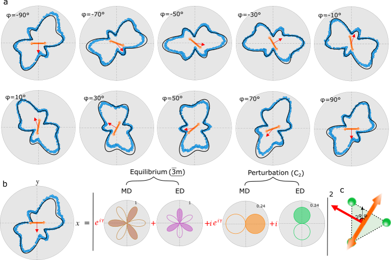
Compared to the equilibrium case, only two additional independent terms are permitted to model the RA pattern: perturbations to the in-plane electric and magnetic dipole susceptibilities, and , respectively. In Fig. 3(b), we demonstrate that Eq. 5 yields an excellent fit to the RA pattern when the pump polarization is along -axis (i.e. ). (In Supplementary Note IIC, we explain how the combined parity and time-reversal symmetry accounts for the factor of multiplying the perturbative terms in Eq. 5).
Our assignment of a light-induced electronic dipole moment is corroborated by two non-trivial predictions of our fit model. First, as the pump polarization angle, , is varied, the induced dipole moment is correspondingly rotated by an angle (Eq. 4 and 5). In Fig. 3(c), we illustrate this concept visually with the orange and red arrows which represent the orientation of the pump polarization and induced dipole moment, respectively. Once the RA pattern at is fit (Fig. 3(b)), the dependence on the pump polarization angle, , is completely determined by Eq. 5. In Fig. 3(a), we show the dependence of the RA pattern on the pump polarization angle , while the corresponding results generated using Eq. 5 are shown in black. Even though the RA patterns change shape as the pump polarization is tuned, the black curves nonetheless show remarkable agreement with the data. We emphasize that these are not fits to the individual RA patterns; only the pattern is fit and the remaining black lines are generated with Eq. 5, where only a single parameter, , is varied. Second, by choosing the opposite sign of and in Eq. 5 (terms proportional to the order parameter), we obtain excellent agreement to the RA pattern of the opposite antiferromagnetic domain state. Again, the black line in the right panel of Fig 2(b) is not a fit, but is generated from this procedure. This scheme implies that the two AFM domain states exhibit opposite induced dipole moments.
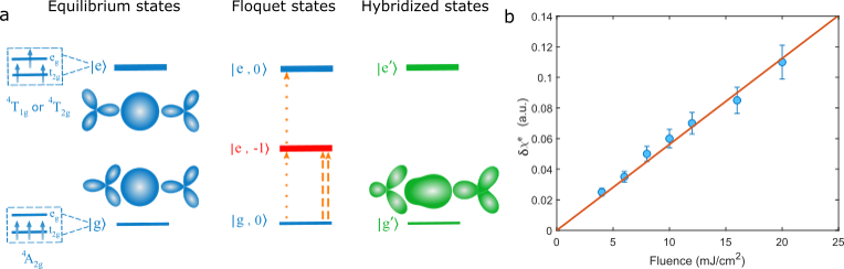
The model itself does not explain how the symmetry is broken from a microscopic standpoint, however. To understand how this is accomplished, we appeal to the useful picture provided by Floquet theory shirley ; nonlinearFloquet . In the leftmost panel of Fig. 4(a), we schematically illustrate the energy levels of the Cr atoms in the crystal field environment with the ground state and the excited states , and show examples of the corresponding in-plane probability densities. When a periodic potential is applied to the system, a series of Floquet sidebands or “dressed states” emerge, which we label , where labels the equilibrium state from which the Floquet sideband derives. In the middle panel of Fig. 4(a), we make the rotating wave approximation and only show a single dressed state of the excited state manifold, . In this effectively time-independent scheme, a superposition state, forms, where the numerator of is given by matrix elements of the form , and the power of indicates a first or second order perturbative correction to the ground state shirley . Here, is the dipole operator and is the time-independent electric field vector. Such matrix elements sensitively depend on the polarization of the incoming light.
The new hybridized state, , is capable of exhibiting a static dipole moment, which can be seen by calculating the expectation value (Supplementary Note IX). With the orange arrows in the middle panel of Fig. 4(a), we illustrate the two pathways through which the dipole can develop. The first path is shown with the dotted arrows and indicates that a dipole can arise due to terms of the form . A second pathway, shown with the dashed arrows, yields terms of the form . Selection rules associated with such matrix elements have been previously been calculated for Cr2O3 in Refs. Cr2O3book ; ME0 ; ME1 ; ME2 . We use the matrix elements therein to sketch representative probability densities for the first kind of process, which we show in the rightmost panel of Fig. 4(a). Clearly, the in-plane threefold symmetry of the crystal is broken and a finite dipole moment can be observed. (Supplementary Note VIII clarifies the symmetries of the sketched probability densities. Further details of the calculation using time-dependent perturbation theory and Floquet theory are presented in Supplementary Note IX.)
It is important to note that both pathways give rise to terms that scale with . Such a relation implies that the lowest order static electric dipole moment scales with (i.e. fluence), which is confirmed experimentally in Fig. 4(b). This scaling is consistent with the second order nonlinear optical process producing a field conjugate to the electronic dipole moment.
In conclusion, our experimental observations and simple theoretical account demonstrate how Floquet engineering can be used to manipulate the symmetry of electronic orbitals. The macroscopic symmetry of the electronic subsystem subsequently decouples from that of the lattice on an ultrafast timescale to break in-plane rotational symmetry and to produce a purely electronic dipole moment. This experiment builds on previous work showing that purely electronic macroscopic effects in crystals can be brought about through the coherent nonlinear interaction of light with matter InverseFaraday ; InverseFaradayNiO ; InverseCMENiO ; InverseCM ; mciver ; MnPS3 ; WS2 ; WS22 ; Yihua ; Fahad . Our work paves the way towards quantifying the electronic contribution to the ferroelectric effect, engineering electronic phases with light, and manipulating magnetism via an electronic magnetoelectric effect in candidate materials contribution1 ; contribution2 ; magnetism1 ; type2MEa ; type2MEb ; reviewME1 ; reviewME2 .
I Acknowledgements:
We thank Mengxing Ye, Honglie Ning, Carina Belvin and Wesley Campbell for helpful conversations related to this work. Research at UCLA was supported by the U.S. Department of Energy (DOE), Office of Science, Office of Basic Energy Sciences under Award No. DE-SC0023017 (experiment and theory). The work at Rutgers was supported by W. M. Keck Foundation (materials synthesis). A.B.C. and R.R. acknowledge financial support from the University of California Laboratory Fees Research Program funded by the UC Office of the President (UCOP), grant number LFR-20-653926. A.B.C acknowledges financial support from the Joseph P. Rudnick Prize Postdoctoral Fellowship (UCLA).
II Author contributions:
X.Z. and T.C. built the SHG setup and performed the time-resolved SHG experiments under the supervision of A.K. X.Z. analysed the data under the supervision of A.K. K.D. and K.W. grew the single crystals under the supervision of S.-W.C. Theoretical calculations were carried out by A.B.C. with input from R.R., X.Z and A.K. The manuscript was written by X.Z., A.B.C. and A.K. with input from all authors.
III Competing interests:
The authors declare no competing interests.
IV Methods
IV.1 Sample synthesis
Cr2O3 single crystals were grown using a laser diode heated floating zone (LFZ) technique. Cr2O3 powders (Alfa Aesar, ) were pressed into 3 mm diameter rods under 8000 PSI hydrostatic pressure. The compressed rod was sintered at 1600∘C in a box furnace for 10 hours. The crystals were grown with growth speed of 2 to 4 mm/h in oxygen flow of 0.1 l/min, and counter rotation of the feed and seed rods at 15 and 15 rpm, respectively.
IV.2 Experimental details
The regeneratively amplified laser used in our experiment is based on a Yb:KGW gain medium that outputs a power of 10 W. The laser pulses have a Gaussian-like profile with an approximately 180 fs pulse duration and a 1030 nm central wavelength. In our experiment, we used a laser pulse repetition rate of 5 kHz. The fundamental output of the laser at 1030 nm was used as the pump pulse, which was focused obliquely on the sample at a 10 degree angle of incidence. The pump laser spot size was 500 m and the maximum fluence was 20 . The probe pulse was generated from an optical parametric amplifier with tunable wavelength, which we use for the second harmonic spectroscopy between 900-1200 nm. The probe pulse was focused normally on the sample with a 100 m spot size, and the probe fluence was 2 . Detection of the second harmonic light was conducted with a commercial photo-multiplier tube. The sample was cooled to 150 K with a standard optical cryostat with fused silica windows to prevent distortions to the light polarization.
V Data availability
The data that supports the findings of this study are present in the paper and/or in the supplementary information, and are deposited in the Zenodo repository. Additional data related to the paper is available from the corresponding authors upon reasonable request.
References
- (1) Powell, R. Symmetry, group theory, and the physical properties of crystals Springer (2010).
- (2) Kivelson, S.A., Fradkin, E. Emery, V. Electronic liquid-crystal phases of a doped Mott insulator. Nature 393, 550-553 (1998).
- (3) Lilly, M.P. et al. Evidence for an anisotropic state of two-dimensional electrons in high Landau levels. Phys. Rev. Lett. 82, 394 (1999).
- (4) Feldman, B.E. et al. Observation of a nematic quantum Hall liquid on the surface of bismuth. Science 354, 316-321 (2016).
- (5) Borzi, R. et. al. Formation of a nematic fluid at high fields in Sr3Ru2O7 at high magnetic fields. Science 315, 214-217 (2007).
- (6) Harter, J. et al. A parity breaking electronic nematic phase transition in the spin orbit coupled metal Cd2Re2O7 Science 356, 295-299 (2017).
- (7) Wu, J. et al. Spontaneous breaking of rotational symmetry in copper oxide superconductors. Nature 547, 432-435 (2017).
- (8) Chu, J. et al. Divergent nematic susceptibility in an iron arsenide superconductor. Science 337, 710-712 (2012).
- (9) Wu, J. et al. Electronic nematicity in Sr2RuO4. Proc. Natl. Acad. Sci. 117, 10654-10659 (2020).
- (10) Ronning, F. et al. Electronic in-plane symmetry breaking at field-tuned quantum criticality in CeRhIn5. Nature 548, 313-317 (2017).
- (11) Okazaki, R. et al. Rotational symmetry breaking in the hidden-order phase of URu2Si2. Science 331, 439-442 (2011)
- (12) Sirica, N. et al. Photocurrent-driven transient symmetry breaking in the Weyl semimetal TaAs. Nat. Mater. 21, 62–66 (2022).
- (13) Sirica, N. et al. Tracking Ultrafast Photocurrents in the Weyl Semimetal TaAs Using THz Emission Spectroscopy. Phys. Rev. Lett. 122, 197401 (2019).
- (14) Shirley, J. Solution of the Schrodinger equation with a Hamiltonian periodic in time Phys. Rev 138, 4B (1965).
- (15) Oka, T. Kitamura, S. Floquet Engineering of quantum materials. Annu. Rev. Condens. Matter Phys. 10, 387-408 (2019).
- (16) Morimoto, T. Nagaosa, N. Topological nature of nonlinear optical effects in solids. Sci. Adv. 2, 5 (2016).
- (17) Kimel, A. et al. Ultrafast non-thermal control of magnetization by instantaneous photomagnetic pulses. Nature 435, 655–657 (2005).
- (18) Satoh, T. et al. Spin oscillations in antiferromagnetic NiO triggered by circularly polarized light. Phs. Rev. Lett. 105, 077402 (2010).
- (19) Tzschaschel, C. et al. Ultrafast optical excitation of coherent magnons in antiferromagnetic NiO. Phs. Rev. B 95, 174407 (2017).
- (20) Pershan, P.S., van der Ziel, J.P. Malmstrom, L.D. Phys. Rev. 143, 574-583 (1966).
- (21) Shan, J. et al. Giant modulation of optical nonlinearity by Floquet engineering Nature 600, 235–239 (2021).
- (22) Sie, E. et al. Valley-selective optical Stark effect in monolayer WS2. Nat. Mater. 14, 290–294 (2015).
- (23) Sie, E. et al. Large, valley-exclusive Bloch-Siegert shift in monolayer WS2. Science 355, 6329 (2015).
- (24) Wang, Y. et al. Observation of Floquet-Bloch States on the Surface of a Topological Insulator Science 342, 453–457 (2013).
- (25) Mahmood, F. et al. Selective scattering between Floquet–Bloch and Volkov states in a topological insulator. Nat. Phys. 12, 306–310 (2016).
- (26) McIver, J.W. et. al. Light-induced anomalous Hall effect in graphene. Nat. Phys., 16 38-41 (2020).
- (27) Boyd, R. Nonlinear optics. Academic Press (2020).
- (28) Bass, M. et al. Optical Rectification. Phys. Rev. Lett. 9, 446 (1962).
- (29) Kaplan, D., Holder, T. and Yan, B. Nonvanishing subgap photocurrent as a probe of lifetime effects. Phys. Rev. Lett. 125, 227401 (2020).
- (30) Fiebig, M., Pavlov, V. Pisarev, R. Second-harmonic generation as a tool for studying electronic and magnetic structures of crystals: review J. Opt. Soc. Am. B 22, 1, 96-118 (2005).
- (31) Fiebig, M. et al. Second Harmonic Generation and Magnetic-Dipole —Electric-Dipole Interference in Antiferromagnetic Cr2O3 Phys. Rev. Lett. 73, 2127 (1994).
- (32) Fiebig, M.,Fröhlich, D. Sluyterman, G. Domain topography of antiferromagnetic Cr2O3 by second‐harmonic generation. Appl. Phys. Lett. 66, 2906 (1995).
- (33) Satoh, T. et al. Ultrafast spin and lattice dynamics in antiferromagnetic Cr2O3 Phys. Rev. B 75, 155406 (2007).
- (34) Satoh, T. et al. Time-resolved demagnetization in Cr2O3 by phase sensitive second harmonic generation Phys. Rev. B 310, 1604-1606 (2007).
- (35) Sala, V. et al. Resonant optical control of the structural distortions that drive ultrafast demagnetization in Cr2O3 Phys. Rev. B 94, 014430 (2015).
- (36) Birss, R. Symmetry and Magnetism. North Holland, (1966).
- (37) Muthukumar, V., Valentí, R. Gros, C. Microscopic Model of Nonreciprocal Optical Effects in Cr2O3 Phys. Rev. Lett. 75, 2766 2766 (1995).
- (38) Muto, M. et al. Magnetoelectric and second-harmonic spectra in antiferromagnetic Cr2O3 Phys. Rev. B 57, 9586 (1998).
- (39) Muthukumar, V., Valentí, R. Gros, C. Theory of nonreciprocal optical effects in antiferromagnets: The case of Cr2O3 Phys. Rev. B 54, 433 (1996).
- (40) Tanabe, Y., Fiebig, M. Hanamura, E. in Magneto-optics eds. Sugano, S. Kojima, N. Springer 128, 107 (1999).
- (41) Malashevich, A. et al. Full magnetoelectric response of Cr2O3 from first principles Phys. Rev. B 86, 094430 (2012).
- (42) Bousquet, E., Spaldin, N. Delaney, K. Unexpectedly Large Electronic Contribution to Linear Magnetoelectricity Phys. Rev. Lett. 106, 107202 (2011).
- (43) Kirilyuk, A., Kimel, A. Rasing, T. Ultrafast optical manipulation of magnetic order Rev. Mod. Phys. 82, 2731 (2010).
- (44) Khomskii, D. Classifying multiferroics: mechanisms and effects. Physics 2, 20 (2009).
- (45) Tokura, Y., Seki, S. Nagaosa, N. Multiferroics of spin origin. Rep. Prog. Phys. 77, 076501 (2014)
- (46) Spaldin, N. Ramesh, R. Advances in magnetoelectric multiferroics Nat. Mater. 18, 203–212 (2019).
- (47) Spaldin, N. Fiebig, M. The Renaissance of Magnetoelectric Multiferroics Science 309, 391-392 (2005).