Low-Complexity Codebook Design for SCMA based Visible Light Communication
Abstract
Sparse code multiple access (SCMA), as a code-domain non-orthogonal multiple access (NOMA) scheme, has received considerable research attention for enabling massive connectivity in future wireless communication systems. In this paper, we present a novel codebook (CB) design for SCMA based visible light communication (VLC) system, which suffers from shot noise. In particular, we introduce an iterative algorithm for designing and optimizing CB by considering the impact of shot noise at the VLC receiver. Based on the proposed CB, we derive and analyze the theoretical bit error rate (BER) expression for the resultant SCMA-VLC system. The simulation results show that our proposed CBs outperform CBs in the existing literature for different loading factors with much less complexity. Further, the derived analytical BER expression well aligns with simulated results, especially in high signal power regions.
Index Terms:
CB Design, Input-Dependent Gaussian Noise (IDGN), Sparse Code Multiple Access (SCMA), Visible Light Communication (VLC).I INTRODUCTION
In recent years, visible light communication (VLC) has emerged as a reliable alternative to legacy radio-frequency (RF) based communication, especially for indoor scenarios. VLC offers various advantages such as unlicensed spectrum, free of electromagnetic interference, and ease of deployment using existing illumination infrastructure along with high-level security [1, 2, 3]. Besides, non-orthogonal multiple access (NOMA) has received increasing research attention in the past few years as a key technology for the enabling of massive machine type communication (mMTC) systems, in which a massive number of devices with very high density needs to be served [4], [5]. The primary concept behind NOMA is to serve multiple users over the same resource elements (frequency or time slots) using different codebooks (CBs) or power levels. This paper is concerned with the integration of VLC with a disruptive NOMA scheme, called sparse code multiple access (SCMA), where multiple users are served simultaneously with different sparsity structures of the CBs [6]. Message passing algorithm (MPA) is used for multi-user detection by taking advantage of the sparse CBs [7]. In SCMA, CB design plays a key role in the enhanced error rate performances [8].
To support multiple access in VLC, conventional orthogonal frequency division multiple access (OFDMA) may not be employed as VLC has the requirement of real and positive signal transmission. In order to overcome the above drawback, direct current-biased optical OFDMA (DCO-OFDMA) and asymmetrically clipped optical OFDMA (ACO-OFDMA) have been studied. However, DCO-OFDMA suffers from deteriorated bit error rate (BER), and ACO-OFDMA suffers from reduced spectral efficiency [9]. In comparison, SCMA can be combined with VLC to increase the spectral efficiency because of the following reasons [10]:
-
•
The dominant line-of-sight (LOS) component and the short distance between light-emitting diode (LED) and photodetector (PD) give rise to a high signal-to-noise ratio (SNR) at VLC receiver, which helps improve the performance of SCMA.
-
•
The limited modulation bandwidth of the LEDs can be efficiently utilized by SCMA to achieve high spectral efficiency.
Several research works incorporating SCMA in VLC (SCMA-VLC) systems have been presented in the literature. In [11], [12], experimental demonstration of SCMA-VLC system with overloading factor of 1.5 was reported 111The overloading factor of 1.5 means that the number of users is 1.5 times the number of resource elements..
In [13], a hybrid power-domain SCMA was investigated for VLC, showing improved data rate at the cost of reduced transmission distance. In [14], color-domain SCMA was proposed for VLC for a large throughput gain over conventional white light SCMA system. All the above works used the predefined RF complex SCMA CBs and made suitable changes (such as Hermitian symmetry and DC-level shifting) so that they can be applied to the VLC system. The authors in [15] focused on SCMA constellation design for VLC system in the presence of thermal noise with six users and eight resource elements (REs). In [16] and [17], SCMA CB has been designed for three users with four REs considering the impact of varying shot noise in VLC systems. Although [15, 16, 17] have proposed SCMA CBs for different VLC systems, however, there is still a lack of literature on designing SCMA CBs with overloading factor greater than one while considering the presence of shot noise in VLC systems.
Previously, the analytical expression of BER has been discussed [18, 19] either for power-domain NOMA techniques or for single-carrier scheme (such as on-off keying) for shot noise incorporated VLC systems. However, SCMA is a multi-carrier scheme, and its BER analysis will be different from single-carrier schemes. Further, when the SCMA-VLC system incorporates varying shot noise, the conventional closed-form BER expression does not follow the simulation results. Therefore, an exact theoretical BER expression for shot noise incorporated SCMA-VLC system has been proposed in this work.
To the best of our knowledge, this paper is the first known work that proposes the SCMA CB design with 1.5 overloading factor for VLC systems considering shot noise.
The contributions of this paper are summarized as follows:
-
•
A novel multidimensional, low-complex, and power-efficient SCMA CB designing technique has been proposed for shot noise incorporated VLC system utilizing the log-sum-exponential operation in the optimization objective function of CB design. The proposed CBs outperform CBs in the existing literature [16, 17] for different load factors with much less complexity.
-
•
The proposed optimization problem and its solution lead to flexible SCMA CBs which can meet the need of SCMA-VLC systems with varying loading factors.
-
•
The analytical expression of BER for SCMA-VLC system considering the shot noise has been derived. The simulation results show good agreement with the derived analytical BER expression, especially for higher signal power region.
The remainder of the paper is organized as follows. The SCMA-VLC system model is discussed in Section II. The proposed CB design and the theoretical BER expression for SCMA over shot noise VLC system are discussed in Section III. The results are presented and analyzed in Section IV. Section V concludes the paper.
Notations: Throughout this paper, x, x, X denote a scalar, vector and a matrix, respectively. Symbols and represent transpose of x and X, respectively. The th element of vector x is denoted by and denotes the th row and th column element of matrix X. Symbols and represents the set of binary numbers and, real and positive numbers, respectively. The diagonal matrix is denoted by diag(x) where the th diagonal element is and ‘log(x)’ denotes the natural logarithm of each element of x, respectively. The maximum value of as is varied over all its possible values is denoted by ‘’. The probability density function (PDF) of a Gaussian random variable (RV) with mean and variance is denoted by . The trace of a square matrix A is denoted by which is calculated by the sum of main diagonal elements of A. The selection of elements from a set of elements is denoted by and denotes the L2 norm of x, respectively.
II System Model
II-A Input-dependent Gaussian noise
In the VLC system, the optical receiver (i.e., PD) measures the intensity of the incident optical signal and converts it into electrical signal. The interaction of the incoming photons with the matter of PD is a statistical process [20]. The fluctuations in the number of photons detected, results in fluctuating current which cause shot noise at the optical receiver. The generated shot noise depends on the incident optical signal itself [21, 22, 23]. Further, the thermal motion of the electronic carriers result in fluctuating voltage known as thermal noise. In case of strong ambient light, the impact of thermal noise is more and the shot noise becomes very low. Thus, the noises at the VLC system are assumed to be independent of the received signal [24, 25, 26]. However, in case of indoor scenario, the distance between transmitter and receiver is less and the dominant signal is LOS [27], thus the received power is large. However, in practical VLC systems, typical illumination and communication scenarios offer very high SNR[28, 29]. In case of indoor scenario (as considered in our work), since the received power is large, the shot noise is more dominant and cannot be neglected. The variance of shot noise is given as
| (1) |
where is the electronic charge, is the intensity of incident optical signal, is responsivity, is the background noise current,
and is the noise-bandwidth factor, and B is the effective bandwidth of the optical receiver.
The thermal noise is assumed to be Additive white Gaussian noise (AWGN), which is independent of the intensity of the incident signal [21]. The shot noise affected optical intensity channel can be distinguished as an input-dependent Gaussian noise (IDGN), where variance of IDGN can be used to characterise the physical properties of the VLC system [21, 30]. Consequently, the received signal can be expressed as
| (2) |
where denotes a real Gaussian RV with zero mean and variance describing IDGN (shot noise), and describes the thermal noise. Here, and are assumed to be independent, and denotes the strength of shot noise with respect to thermal noise. In an indoor scenario, as the transmitter and the receiver parameters change, the received power changes, and thus the shot noise varies. In this paper, the variation in shot noise has been depicted by considering different shot noise factor values.
II-B The SCMA-VLC Model
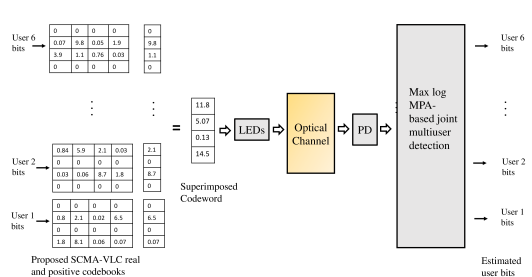
Consider a downlink indoor LOS VLC system where multiple users are being served, each equipped with a single receiving device. Every users are grouped together for SCMA, and each group is supported by REs (e.g., time or frequency slots), providing the load factor . In Fig.1, the data transmission and reception of six users () on four REs () with is shown.
At the transmitter, bits are mapped to -dimensional real and positive codewords, with number of codewords in a CB. These codewords are sparse vectors with non-zero elements, . Each user has a dedicated CB allotted to it. The CB of th user can be expressed as
| (3) |
where and denote the mapping matrix and constellation matrix of the th user, respectively. The constellation matrix , where denotes the th constellation point of . The whole CB structure of SCMA can be represented by the factor graph matrix, , where . The user is being served by resource node (RN) , if . For a SCMA block having REs and users, one example of the factor graph matrix of size is given as
| (4) |
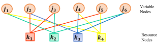
Fig. 2 shows an example of factor graph representation of six users (or Variable Nodes (VNs)) with four RNs, =2 and data of users is being superimposed on each RN ( for shown in (4)). The binary mapping matrices corresponding to the six users are given below
| (5) |
The set of CBs for users is dependent on the constellation matrices as the mapping matrices remain fixed as shown in (5). Assuming synchronous multiplexing between users, the received signal can be expressed as
| (6) |
where is a codeword of th user, denotes the channel matrix of th user, the second term represents the IDGN with , and . The channels are assumed to be unit vectors for simplicity, and the extension to the general VLC values is straight-forward. In case of the movement of the users, the channel characteristics of the users of th user in will be affected. The random waypoint (RWP) mobility model is a simple and straightforward stochastic model that describes a human movement behavior in indoor scenarios [31]. In case of user mobility, the received signal expression remains same as (6), however the channel vector (h) varies as per the RWP model in (6).
II-C SCMA-VLC Decoding
Assuming perfect channel estimation and the set of CBs known to receiver, the SCMA multi-user codeword can be detected by solving the joint maximum a-posteriori (MAP) probability mass function (PMF) of the transmitted codewords [7], [32]. The estimated X can be written as
| (7) |
where represents the set of codewords allotted to the th user. The marginal distribution of (7) with respect to (i.e., summing the joint PMF of multi-user codeword over all values of X except ) leads to th user detected symbol as
| (8) |
Using Bayes’ rule
| (9) |
where denotes the joint a-priori PMF of all transmitted codewords and denotes the conditional pdf of the received vector. Assuming noise components are independent and identically distributed for all REs. Then (9) becomes
| (10) |
where denotes the received signal at the th RE. Solving the above marginal product of function (MPF) problem with brute force will lead to exponential complexity. Taking advantage of sparse CBs, this problem can be approximately solved by iterative MPA with moderate complexity [7], [33]. MPA works as a decoding algorithm based on passing the extrinsic information between RNs and VNs. The first message is passed from the leaf node (node which has only one neighboring node), and a node of degree will remain idle until it has received messages from the number of neighboring nodes. MPA involves a large number of exponential operations which are of high complexity. A mathematical simplification is to move MPA to logarithm domain and use Jacobian logarithm, which gives a simpler version called Max-Log-MPA [34]. With Jacobian logarithm, the log-sum of exponentials can be approximated as a maximum operation as shown below:
| (11) |
The Max-Log-MPA for detection of SCMA codewords in VLC is based on three steps as shown in Algorithm 1. Let and , be the set of nodes connected to VN and RN , respectively. Let and be the message passed from RN to VN and vice-versa. Also, denotes all the VNs of except VN and denotes the RNs in except the th RN.
In Algorithm 1, it is assumed that the received signal y and all the CBs Cj, are known at the receiver. The total number of iterations considered in Step 2 are and, VNs and RNs are updated for each iteration . Also, the channel coefficient between th RN and th VN is denoted by and the codeword element transmitted by th VN on th RN is denoted by , respectively.
In the case of shot noise, the variance at each RN is different and dependent on the superimposed codeword element at the corresponding RN, while in the presence of only thermal noise, , so and variance will be the same for all RNs. In case of three users scenario, the factor graph would not be cyclic and number of elements being superimposed on each RN would be different ( for and for ). Since is different for different REs, therefore, Algorithm 1 will change accordingly [35].
The computational complexity of standard MPA and Max-Log-MPA considering the effect of shot noise in decoding is shown in Table I [36]. The number of operations is shown for the update step of RN as shown in Step 2 (a) of Algorithm 1. Max-Log-MPA requires more addition operations and less multiplication operations than MPA. This gap of increase in addition and decrease in multiplication operations between MPA and Max-Log-MPA increases with the overloading factor.
| Operations | MPA | Max-Log-MPA |
|---|---|---|
| Exponential | 0 | |
| Multiplication | ||
| Addition | ||
| Comparison | 0 |
III CB Design and Optimization
For SCMA CB design and optimization, most researchers aim for maximization of the minimum Euclidean distance (MED) between the superimposed codewords [37, 38, 39]. In this section, a method of designing constellation matrices is introduced and discussed as an optimization problem.
III-A The Problem Formulation
In the AWGN channel, MED is taken as one of the key performance indicators for determining the performance of the designed SCMA CB. Let be a superimposed codeword from the combined constellation matrix . Then, the MED between and is given as
| (12) |
The MED emerge as a critical parameter because of the pair-wise error probability (PEP) for AWGN channel which is given as
| (13) |
However, in case of IDGN, the PDF of the received signal y is given as (assuming unit channel gain)
| (14) |
where denotes the covariance matrix for the th superimposed codeword. It can be seen from (14) that the variance is now dependent on the superimposed codeword.
In the case of only thermal noise, MED is taken as a critical parameter for designing CB where variance is independent of the superimposed codeword. However, in the case of shot noise, when variance is no longer independent, the conventional MED cannot serve as an optimal performance indicator. With the effect of shot noise, the shape of constellation points gets distorted. To mitigate the effect of IDGN, the authors in [16] introduced an improved optimization objective based on Rotated-MED for designing constellation matrices. The rotated Euclidean distance (RED) between superimposed codewords and can be expressed as
| (15) |
where , and represents the Identity matrix. It is to be noted from (15) that the new parameter RED incorporates the shot noise effect while computing the Euclidean distance between superimposed codewords. The authors in [16] aimed at maximizing the rotated minimum Euclidean distance (R-MED) subject to the power constraints. The objective function proposed in [16] for SCMA CB design is given as
| (16) |
where . This was further simplified as
| (17) |
where denotes the minimum value of RED. It has been verified in [16] that R-MED based CB outperforms the MED based CB for VLC systems affected by shot noise. The results in [16] have shown that for and , BER of is achieved at and for MED and R-MED based CBs, where denotes the maximum electrical power allotted to a user. Since from the literature we can understand that RED works as an important parameter for designing CB than MED, we have included RED in our optimization problem. Further, the authors in [17] introduced the concept of distance range (DR) based on the maximum and the minimum values of the RED. They have mentioned that for the low to medium SNR region, the BER is no longer dependent on just R-MED. The optimization problem proposed in [17] for CB designing is
| (18a) | |||
| (18b) | |||
| (18c) | |||
| (18d) | |||
| (18e) |
where denotes the maximum value of RED, and denotes the weighting factor. The objective function shown in (18a) is dependent on and . The real and positive optical signal constraint is considered in (18b) and maximum electrical power constraint is considered in (18c). All the REDs will lie between and (18d, 18e). Also, it is to be noted that, lesser the overlapping between the constellation points of a user, better the performance of the designed CBs.
III-B The Objective Function
The objective function mentioned in (16) considers all the REDs while designing and optimizing the CBs to get optimum results. However, considering all the REDs makes the objective function non-convex and non-differentiable [40]. To solve (16), authors in [17] have proposed the objective function as shown in (III-A). It should be noted that the numerical methods used for solving the nonlinear maxi-min problem aim at approximating the by close enough smooth functions, and the closeness of approximation decide the nearness to optimal solutions [41]. If we consider , the approximation to becomes better when is a strong convex function (i.e., large positive second derivative). One approach to solve this non-convex problem is to use well known “log sum-exponentials” continuous approximation [42], [43]. With this approximation, the objective function in (16) transforms to
| (19) |
where is a tuning parameter which results in the smoothness of (19) and affects the accuracy of the model.
-
•
Example 1: Let , and there are two distances , then
The function in (19) is differentiable but still non-convex; however, optimization algorithms based on the derivation of the Hessian of the objective function can find the local optimal solution [44]. Also, if the objective function is optimized number of times with initialization from small set of random numbers and choosing the parameter wisely, the likelihood of obtaining the global optimal solution increases [45]. Thus, the optimization problem is formulated as
| (20a) | |||
| (20b) | |||
| (20c) | |||
where (20b) denotes the real positive intensity constraint of the transmitted codeword elements and (20c) denotes that the average electrical power of the generated codewords should be less than the maximum electrical power () allotted per user. The optimization problem in (20) can be solved using commercially available solvers like MATLAB’s . The procedure for solving the above optimization problem is summarized in Algorithm 2.
III-C Complexity Analysis
For the case of the proposed optimization problem in (20), initially, the set of all multiplexed vectors (or superimposed codewords) is computed. With users and number of codewords in the CB, the number of superimposed codewords obtained are , i.e., . Since the complexity of operations such as addition and subtraction is therefore, the complexity of computing multiplexed vectors is . Next, for generating the covariance matrix ( for superimposed codeword), each multiplexed vector is multiplied with the scalar which results in the complexity . The complexity of computing RED (as shown in (15)) between two multiplexed vectors is as the length of each vector is and the total number of multiplexed vectors are . Thus, the total number of REDs between multiplexed vectors is and the total complexity for calculating REDs will be . Next, the complexity of computing the objective function (20a) is . The complexity of constraints in (20b) and (20c) is since it includes addition and square operations. The maximum value of at which the algorithm converges is denoted by and number of iterations for the MATLAB’s solver is , then total complexity to generate the constellation matrices for users using Algorithm 2 is . If we take the most dominant part resulting for complexity, it is equal to .
In case of the DR based CB [17] optimization problem (as shown in (III-A)), the total complexity comes from the computation of the objective function and four constraints. The third and fourth distance based constraints (18d, 18e) are non-convex and are approximated using first order Taylor series [16]. From the calculation of multiplexed vectors, covariance matrices and REDs, the complexity is . The complexity of intensity and power constraints (18b, 18c) is . For the approximation of two non-convex constraints (18d, 18e), firstly the coefficient matrix is calculated to obtain multiplexed vector from L [16], and its complexity is . Next, we found that the derivative of RED has the highest complexity because of the kronecker product operation involved. The derivative term has the complexity . So, with as total number of outer loop iterations, the total complexity is . Taking only the dominant part, the complexity becomes . It can be observed that the proposed Log-sum-exp scheme (20) has reduced the computation complexity of SCMA CB design by a significant amount from DR based CB optimization problem shown in (III-A).
III-D Theoretical BER
SCMA is a multi-carrier scheme, i.e., the superimposed transmitted codeword is a dimensional real codeword as discussed in Section II-B. In this section, the theoretical BER expression has been derived for the IDGN incorporated SCMA-VLC system. For only the thermal noise case, the PEP is given as (13). However, in the case of shot noise, the overall variance changes and is dependent on and the intensity of the incident optical signal. The error rate for the superimposed codeword is
| (21) | |||
| (22) |
where and , denotes the th element of the superimposed codeword and , respectively. The th diagonal element of the covariance matrix of the superimposed codeword is denoted by . The diagonal element denotes the total variance at th RE when was transmitted. The total probability of error is given as [46]
| (23) |
where denotes the a priori probability of , denotes the bit error when is chosen over and denotes the PEP between and .
IV Results and Discussion
In this section, the simulation and theoretical results of the BER performance of the proposed SCMA CB are presented. Firstly, using Algorithm 2, we can generate the proposed CBs for different users. Further, Max-Log-MPA (as shown in Algorithm 1) has been used for multi-user detection.
IV-A RF based CBs Performance in VLC system
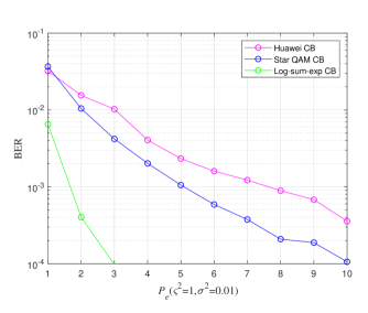
We consider the case where RF-based CBs are used for transmitting data over a VLC system. We consider the SCMA CBs from [37] and [47]. RF CBs cannot be employed as it is, as the VLC system has the requirement of real and positive signal transmission. So, the complex codeword elements are divided into real and imaginary parts, which are then DC biased to get real and positive codeword elements [37], [47]. These real and positive codewords are transmitted over different REs . This way, the data of six users is transmitted over eight REs. Further, we have generated the Log-sum-exp based CB for six users and eight REs scenario using Algorithm 2. Fig. 3 shows the bit error rate (BER) performance of the Star QAM based CB [37], Huawei CB [47] and Log-sum-exp CBs for and . It can be understood from Fig. 3 that CBs designed solely for the VLC system (proposed Log-sum-exp based CB) outperforms the RF-based CBs for shot noise incorporated VLC system. The performance gap observed in Fig. 3 motivated the authors to design CB especially for the SCMA-VLC system.
IV-B The case of three users
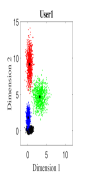
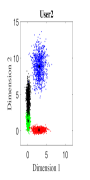
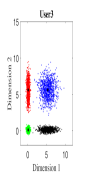
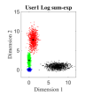
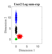
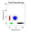
For the initial simulation, we consider the case where three users share four REs with and the number of non-zero elements in the codeword is . The mapping matrices have the same values as shown in (5) (i.e., for and for ). For three users, the CBs (DR based and Log-sum-exp based) are generated by solving the optimization problems (III-A, 20) (CBs are shown in Appendix). For , Algorithm 2 is found to be converging for low values of (i.e., ). Fig. 4. shows the 2-dimensional (2D) scatter plots of the generated DR based CBs (III-A) and the proposed Log-sum-exp based CBs (20) for and . It can be noted that the constellation points under DR criterion (III-A) are substantially overlapping as shown in Fig. 4(a)-4(c). However, the overlapping between proposed Log-sum-exp based constellation points for all three users is negligible as shown in Fig. 4(d)-4(f). As the overlapping increases between different constellation points, it becomes difficult for the receiver to detect the symbols correctly, and thus, the overall performance deteriorates.
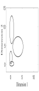
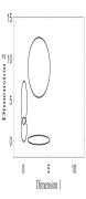
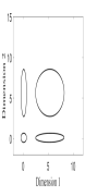
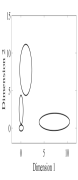
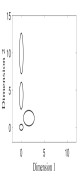
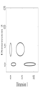
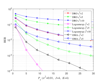
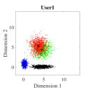
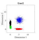
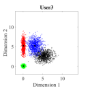
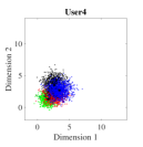
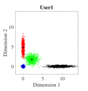
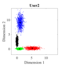
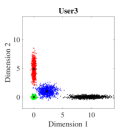
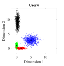
Fig. 5 shows the bit error rate (BER) performance for three users of the proposed Log-sum-exp based (20) SCMA CBs and the DR based CBs (III-A), respectively. The negligible overlapping in the case of log-sum-exp CBs as compared to DR CBs (in Fig. 4), reasons the performance gain obtained in Fig. 5. For both CBs (DR based and Log-sum-exp based), Max-Log-MPA (Algorithm 1) has been used for multi-user detection. It can be noticed that for the low value of (e.g., ), BER performance of both CBs is close, and for high values of (e.g., ), the proposed Log-sum-exp based CBs yield better performance gain as compared to DR based CBs. This suggests that the objective function with all the REDs results in better CB (i.e., Log-sum-exp based CB) than the CB with only minimum and maximum values of REDs (i.e., DR based CB). It is shown that our proposed CBs achieve the BER of at while DR based CB achieve it at for . This suggests that for large values of , the advantage of the proposed Log-sum-exp based CB is more significant than DR based CB. Further, from the results it can inferred that, we can reduce the dimming level to = 86.6% of designed power () for .
The bivariate normal density is specified by the 2D constellation points and the variance of these points in different dimensions. Fig. 6 shows the lines of the equal probability density (EPD) functions of the bivariate Gaussian. The center of the ellipse is the 2D constellation point and its shape is determined by the covariance matrix of the 2D constellation points. The principal axes of these ellipses are given by the eigenvectors of the covariance matrix and, semi-major and semi-minor axis are dependent on the eigenvalues, respectively [48]. For , the th constellation point of the th user is and the covariance matrix of this 2D constellation point is denoted by . So, the center of the ellipse is and its shape is determined by . Fig. 6(a)-6(c) shows the lines of EPD for DR based constellation points and Fig. 6(d)-6(f) shows lines of EPD for Log-sum-exp based constellation points, respectively.
IV-C The case with four, five and six users ()
Consider the case where four users share four REs. The Log-sum-exp based CB is designed for four users using Algorithm 2, and its performance is compared with DR based CB. Fig. 7 shows the BER performance of four users where Log-sum-exp based CB outperforms DR based CBs for different values of . The reason behind the performance difference can be understood from the level of overlapping between the constellation points for both CBs in Fig. 8. It can be observed in Fig. 8 that the DR based 2D constellation points suffer from significant overlapping, especially for user 1 (Fig. 8(a)) and user 4 (Fig. 8(d)), while Log-sum-exp based 2D constellation points are barely overlapping. This results in significant performance improvement for Log-sum-exp based CBs. Also in Fig. 7, the comparison with pulse amplitude modulation orthogonal multiple access (4 PAM-OMA) scheme is shown. It is noted that the proposed algorithm outperforms the OMA scheme for different values of . This is expected as the OMA scheme offers no frequency diversity in contrast to the SCMA scheme.
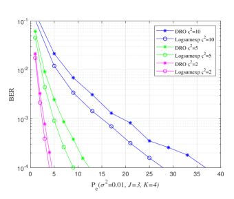
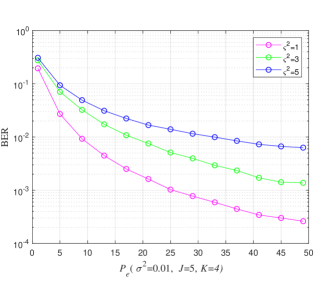
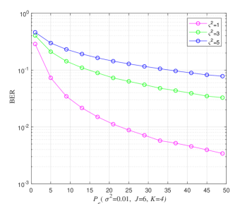
For five users, the complexity of generating DR based CB increases significantly. Further, the performance degrades drastically and requires a very high at BER of . Therefore, the effect of varying shot noise factor with only Log-sum-exp based CBs, when five users data is being transmitted over four REs ( has been shown in Fig. 9. The BER performance with respect to increasing is shown in Fig. 10 for six users. Here, the effect of varying shot noise factor is shown when the proposed Log-sum-exp based CBs have been used for transmitting data over four REs.
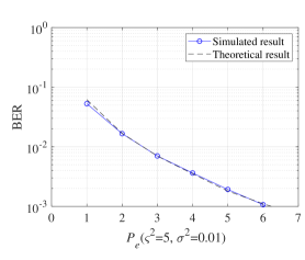
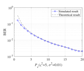
In Fig. 11, the theoretical and simulated BER performances are compared. We find that the simulated curves match with the theoretical curves, especially for the high signal power region. These results verify the correctness of the simulated results obtained in Fig. 5 and Fig. 7. The results from Fig. 5, 7, 9 and 10 have been summarized in Table II. From Table II, we have the electrical power required to achieve BER of for different users and VLC systems with different shot noise factors.
| Number of Users | ||
|---|---|---|
| 3 | 1 | 3 |
| 3 | 5 | 5 |
| 3 | 10 | 15 |
| 4 | 1 | 6.5 |
| 4 | 5 | 29 |
| 5 | 1 | 25 |
| 5 | 3 | 50 |
| 6 | 1 | 50 |
V Conclusion
In this paper, a novel low-complex CB design technique has been proposed for SCMA-VLC system impaired by shot noise. This work emphasizes that the designing of specific CBs is required for the SCMA-VLC system. The proposed CBs are generated by optimizing the Log-sum of exponentials of all REDs between the superimposed codewords. With the inclusion of shot noise in the SCMA system, the overall noise variance is dependent on the strength of the incident signal, as shown in Algorithm 1. The proposed CBs provide improved BER performance as compared to CBs proposed in the existing literature along with reduced complexity. Further, the theoretical analysis of BER is also performed for the shot noise incorporated SCMA-VLC system. The simulated results were validated, and both the theoretical and simulated curves are in good agreement for high signal power regions. In the future, the performance of SCMA codebook can further be enhanced for lower by designing CBs considering lower dimming requirements, and improve the performance of higher load factor scenarios in the SCMA-VLC system.
The DR criteria based SCMA CB for VLC system obtained for three users for and is shown below:
The Log-sum-exp based SCMA CB for VLC system obtained for three users for and is shown below:
Next, the SCMA CB for VLC system generated for four users based on Log-sum-exp for and is shown below:
Similarly, the SCMA CB for VLC system based on the proposed scheme for five users for and is shown below:
At last, we show the SCMA CB for VLC system based on the proposed scheme for six users for and as follows:
Acknowledgment
The authors would like to thank the Associate Editor Dr. Nestor Chatzidiamantis and the anonymous reviewers for their constructive suggestions which have greatly helped to improve the quality of this work. The authors are also thankful to Mr. Vyacheslav P. Klimentyev for the publicly available codes and various discussions.
References
- [1] S. Rajagopal, R. D. Roberts, and S. K. Lim, “IEEE 802.15.7 visible light communication: Modulation schemes and dimming support,” IEEE Commun. Mag., vol. 50, no. 3, pp. 72–82, Mar. 2012.
- [2] M. Kavehrad, “Sustainable energy-efficient wireless application using light,” IEEE Commun. Mag., vol. 48, no. 12, pp. 66–73, Dec. 2010.
- [3] A. Jovicic, J. Li, and T. Richardson, “Visible light communication: Opportunities, challenges and the path to market,” IEEE Commun. Mag., vol. 51, no. 12, pp. 26–31, Dec. 2013.
- [4] Z. Ding, X. Lei, G. K. Karagiannidis, R. Schober, J. Yuan, and V. K. Bhargava, “A survey on non-orthogonal multiple access for 5G networks: Research challenges and future trends,” IEEE J. Sel. Areas Commun., vol. 35, no. 10, pp. 2181-2195, Oct. 2017.
- [5] S. Chen, Y.-C. Liang, S. Sun, S. Kang, W. Cheng, and M. Peng, “Vision, requirements, and technology trend of 6G: how to tackle the challenges of system coverage, capacity, user data-rate and movement speed,” IEEE Wireless Commun., vol. 27, no. 2, pp. 218-228, Apr. 2020.
- [6] H. Nikopour and H. Baligh, “Sparse code multiple access,” in Proc. IEEE 24th Annu. Int. Symp. Pers., Indoor, Mobile Radio Commun., London, UK, Sep. 2013, pp. 332–336.
- [7] R. Hoshyar, F. P. Wathan, and R. Tafazolli, “Novel low-density signature for synchronous CDMA systems over AWGN channel,” IEEE Trans. Signal Process., vol. 56, no. 4, pp. 1616–1626, Apr. 2008.
- [8] M. Taherzadeh, H. Nikopour, A. Bayesteh, and H. Baligh, “SCMA CB design,” in Proc. IEEE 80th Veh. Technol. Conf., Vancouver, Canada, Sep. 2014, pp. 1–5.
- [9] S. Dimitrov, S. Sinanovic, and H. Haas, “Clipping noise in OFDM based optical wireless communication systems,” IEEE Trans. Commun., vol. 60, no. 4, pp. 1072–1081, Apr. 2012.
- [10] H. Marshoud, V. M. Kapinas, G. K. Karagiannidis and S. Muhaidat, ”Non-Orthogonal Multiple Access for Visible Light Communications,” in IEEE Photon. Technol. Lett., vol. 28, no. 1, pp. 51-54, 1 Jan.1, 2016.
- [11] B. Lin, X. Tang, Z. Zhou, C. Lin, and Z. Ghassemlooy, “Experimental demonstration of SCMA for visible light communications,” Opt. Commun., vol. 419, pp. 36–40, July 2018.
- [12] J. An and W.-Y. Chung, “Single-LED multichannel optical transmission with SCMA for long range health information monitoring,” J. Lightw. Technol., vol. 36, no. 23, pp. 5470–5480, 2018.
- [13] B. Lin, X. Tang, and Z. Ghassemlooy, “A power domain sparse code multiple access scheme for visible light communications,” IEEE Wireless Commun. Lett., vol. 9, no. 1, pp. 61–64, 2019.
- [14] R. Mitra, S. Sharma, G. Kaddoum and V. Bhatia, ”Color-domain SCMA NOMA for visible light communication”, IEEE Commun. Lett., vol. 25, no. 1, pp. 200-204, Jan. 2021.
- [15] S. Lou, C. Gong, Q. Gao, Z. Xu, “SCMA with low complexity symmetric CB design for visible light communication,” in Proc. International Conference on Communications (ICC), July 2018, pp. 1–6.
- [16] S. Hu, Q. Gao, C. Gong, Z. Xu, R. Boluda-Ruiz, and K. Qaraqe, “Energy-efficient modulation for visible light SCMA system with signal-dependent Noise,” in Proc. Int. Symp. Commun. Syst., Netw. Digit. Signal Process. (CSNDSP), Budapest, Hungary, Jul. 2018, pp. 1–6.
- [17] Q. Gao, S. Hu, C. Gong, E. Serpedin, K. Qaraqe and Z. Xu, “Distance-range-oriented constellation design for VLC-SCMA downlink with signal-dependent noise,” IEEE Commun. Lett., vol. 23, no. 3, pp. 434–437, 2019.
- [18] J. Y. Wang, J. B. Wang and Y. Wang, “Fundamental Analysis for Visible Light Communication with Input‐Dependent Noise, Optical Fiber and Wireless Communications”, PhD. Rastislav Róka (Ed.), InTech, DOI: 10.5772/68019, (2017).
- [19] V. Dixit and A. Kumar, “An exact BER analysis of NOMA-VLC system with imperfect SIC and CSI,” AEU Int. J. Electron. Commun., vol. 138, Aug. 2021, Art. no. 153864, doi: 10.1016/j.aeue.2021.153864.
- [20] J. M. Senior, and M. Y. Jamro, Optical Fiber Communications: Principles and Practice. 3rd ed. Prentice Hall, 2008.
- [21] S. M. Moser, “Capacity results of an optical intensity channel with input-dependent gaussian noise,” IEEE Trans. Inform. Theory, vol. 58, no. 1, pp. 207-223, Jan. 2012.
- [22] Q. Gao, S. Hu, and Z. Xu, “Modulation designs for visible light communications with signal-dependent noise,” J. Lightwave Technol., vol. 34, no. 23, pp. 5516-5525, Dec. 2016.
- [23] J. Wang, H. Ge, J. Zhu, J. Wang, J. Dai, and M. Lin, “Adaptive spatial modulation for visible light communications with an arbitrary number of transmitters,” IEEE Access, vol. 6, pp. 37 108–37 123, 2018.
- [24] K.-I. Ahn and J. K. Kwon, “Capacity analysis of M-PAM inverse source coding in visible light communications,” J. Lightw. Technol., vol. 30, no. 10, pp. 1399–1404, Jan. 2012.
- [25] J.-B. Wang, Q.-S. Hu, J. Wang, M. Chen, and J.-Y. Wang, “Tight bounds on channel capacity for dimmable visible light communications,” J. Lightw. Technol., vol. 31, no. 23, pp. 3771–3779, Dec. 2013.
- [26] A. Chaaban, Z. Rezki, and M.-S. Alouini, “Fundamental limits of parallel optical wireless channels: capacity results and outage formulation,” IEEE Trans. Commun., vol. 65, no. 1, pp. 296–311, Jan. 2017.
- [27] D. N. Anwar, R. Ahmad and A. Srivastava, ”Energy-Efficient Coexistence of LiFi Users and Light Enabled IoT Devices,” in IEEE Transactions on Green Communications and Networking, doi: 10.1109/TGCN.2021.3116267.
- [28] J. Grubor, S. Randel, K.-D. D. Langer, and J. Walewski, “Broadband information broadcasting using LED-based interior lighting,” J. Lightw. Technol., vol. 26, no. 24, pp. 3883–3892, Dec. 2008.
- [29] L. Hanzo, H. Haas, S. Imre, D. C. O’Brien, M. Rupp, and L. Gyongyosi, “Wireless myths, realities, and futures: From 3G/4G to optical and quantum wireless,” Proc. IEEE, vol. 100, no. Centennial Special Issue, pp. 1853–1888, May 13, 2012.
- [30] H. Chen and Z. Xu, “A two-dimensional constellation design method for visible light communications with signal-dependent shot noise,” IEEE Commun. Lett., vol. 22, no. 9, pp. 1786–1789, 2018.
- [31] C. Bettstetter, H. Hartenstein, and X. Pérez-Costa, “Stochastic properties of the random waypoint mobility model,” Wireless Netw., vol. 10, no. 5, pp. 555–567, 2004.
- [32] Y. Lin, Y. Liu, Y. Siu, “Low complexity message passing algorithm for SCMA system,” IEEE Communications Letters, vol. 20, issue: 12 ,pp. 2466- 2469 Dec. 2016.
- [33] A. Bayesteh, H. Nikopour, M. Taherzadeh, H. Baligh, and J. Ma, “Low complexity techniques for SCMA detection,” in Proc. IEEE Globecom Workshops, San Diego, CA, USA, Dec. 2015, pp. 1-6.
- [34] W. B. Ameur, P. Mary, M. Dumay, J.-F. Hˇelard, and J. Schwoerer, “Performance study of MPA, Log-MPA and Max-Log-MPA for an uplink SCMA scenario,” in Proc. 26th Int. Conf. Telecommun. (ICT), 2019, pp. 411–416.
- [35] F. Kschischang, B. Frey, and H. Loeliger, “Factor graphs and the sum-product algorithm,” IEEE Trans. Inf. Theory, vol. 47, no. 2, pp. 498–519, Feb. 2001.
- [36] J. Liu, G.Wu, S. Li, and O. Tirkkonen, “On fixed-point implementation of Log-MPA for SCMA signals,” IEEE Wireless Commun. Lett., vol. 5, no. 3, pp. 324–327, Jun. 2016.
- [37] L. Yu, P. Fan, D. Cai, and Z. Ma, “Design and analysis of SCMA CB based on Star-QAM signaling constellations,” IEEE Trans. Veh. Technol., vol. 67, no. 11, pp. 10543-10553, 2018.
- [38] V. P. Klimentyev and A. B. Sergienko, ”SCMA CBs optimization based on genetic algorithm,” European Wireless 2017; 23th European Wireless Conference, Dresden, Germany, 2017, pp. 1-6.
- [39] M. Vameghestahbanati, I. Marsland, R. H. Gohary, and H. Yanikomeroglu, “Multidimensional constellations for uplink SCMA systems—A comparative study,” IEEE Commun. Surveys Tuts., vol. 21, no. 3, pp. 2169–2194, third quarter 2019.
- [40] J. M. Luna-Rivera, V. Guerra, J. Rufo-Torres, R. Perez-Jimenez, C. Suarez- Rodriguez, and J. Rabadan-Borges, “Low-complexity colour-shift keying based visible light communications system,” IET Optoelectron., vol. 9, no. 5, pp. 191-198, Oct. 2015.
- [41] J. Nocedal and S. J. Wright, Numerical Optimization. NewYork, NY, USA: Springer-Verlag, 1999.
- [42] R. Chen, “Solution of minimax problems using equivalent differentiable functions,” Comput. Math. Appl., vol. 11, no. 12, pp. 1165-1169, Dec. 1985.
- [43] D. U. Campos-Delgado, J. M. Luna-Rivera, R. Perez-Jimenez, C. A. Gutierrez, V. Guerra, and J. Rabadan, “Constellation design for color space-based modulation in visible light communications,” Phys. Commun., vol. 31, pp. 154-159, Dec. 2018.
- [44] E. Monteiro and S. Hranilovic, “Constellation design for color-shift keying using interior point methods,” in Proc. IEEE Globecom Workshops, Dec. 2012, pp. 1224-1228.
- [45] D. N. Anwar and A. Srivastava, “Constellation design for single photodetector based CSK with probabilistic shaping and white color balance,” IEEE Access, vol. 8, pp. 159 609–159 621, 2020.
- [46] M. K. Simon and M.-S. Alouini, Digital Communication Over Fading Channels, 1st ed. Hoboken, NJ, USA: Wiley, 2000.
- [47] Altera Innovate Asia FPGA Design Contest. (2015). 5G Algorithm Innovation Competition. [Online]. Available: http:// www.innovateasia.com/5g/images/pdf/1st%205G%20Algorithm% 20Innovation%20Competition-ENV1.0%20-%20SCMA.pdf.
- [48] R.O. Duda, P.E. Hart, and D.G. Stork, Pattern Classification. John Wiley & Sons, 2001.