Manifestation of the coupling phase in microwave cavity magnonics
Abstract
The interaction between microwave photons and magnons is well understood and originates from the Zeeman coupling between spins and a magnetic field. Interestingly, the magnon/photon interaction is accompanied by a phase factor which can usually be neglected. However, under the rotating wave approximation, if two magnon modes simultaneously couple with two cavity resonances, this phase cannot be ignored as it changes the physics of the system. We consider two such systems, each differing by the sign of one of the magnon/photon coupling strengths. This simple difference, originating from the various coupling phases in the system, is shown to preserve, or destroy, two potential applications of hybrid photon/magnon systems, namely dark mode memories and cavity-mediated coupling. The observable consequences of the coupling phase in this system is akin to the manifestation of a discrete Pancharatnam–Berry phase, which may be useful for quantum information processing.
I Introduction
Magnons are quasi-particles associated with the collective excitation of spins in magnetic materials. Magnons in ferrimagnetic insulators such as Yttrium-Iron-Garnet (YIG) are promising for information transduction, due to their ability to couple to a plethora of systems, such as mechanical resonators or optical and microwave photonic modes [1, 2]. The emerging field of cavity magnonics focuses on the photon/magnon interaction confined within cavities at microwave or optical frequencies [3, 4, 5]. In the microwave domain, strong and ultra-strong coherent coupling have been demonstrated [6, 7, 8, 9, 10], with the latter even reachable at room temperature [11].
Owing to this flexibility, indirect coupling of two non-interacting systems by an auxiliary mode has been investigated in [12, 13, 14, 15, 16, 17, 18]. For instance, two macroscopically distant magnetic samples in a cavity can indirectly couple by using the cavity photons as a bridge [15, 16, 17, 18, 19, 20, 21]. Notably, in this configuration some eigenmodes are “dark”, in the sense that they do not lead to an experimental signature when probing the system. This dark mode physics can be used to create dark mode gradient memories as experimentally demonstrated in Zhang et al.. Another example of cavity-mediated coupling is the coupling of a magnon with a superconducting qubit, again mediated by a common cavity mode [22, 23]. This versatile configuration motivated studies of quantum magnonics [24], with proposals for single-magnon sources [25, 26], multi-magnon blockade [27], single-shot detection of a single magnon [28] and quantum sensing of magnons [29].
These applications rely on the coupling between microwave photons and magnons, which physically originates from the Zeeman coupling between the spins in the ferrimagnetic material and the cavity’s RF magnetic field [30]. Adopting a quantum formalism to describe this coupling allows for the precise computation of the coupling strength based on microscopic parameters and the cavity geometry [31]. Interestingly, the magnon/photon coupling term resulting from the Zeeman coupling term is accompanied by a phase factor. To the authors’ knowledge, this phase has never been discussed explicitly in the literature, probably due to its inconspicuous nature in the systems considered so far.
The main contribution of this paper is to highlight how the coupling phases can become relevant in systems composed of several magnon and cavity modes. To that effect, we begin by explaining the origin of the coupling phase between a microwave photon and a magnon in section II. In section III, we introduce a hybrid system composed of two YIG spheres, each coupling to two magnetic eigenmodes of a microwave cavity. We show that the various magnon/photon coupling phases in such a system lead to an observable quantity parametrising the Hamiltonian. To illustrate the impact of the physical phase , we study the physics of such a system in section IV, and find that both cavity-mediated coupling and dark mode physics are -dependent.
II Coupling phase between a microwave photon and a magnon
II.1 Free Hamiltonian
In this section, we consider the interaction between one YIG sphere and one magnetic eigenmode of a microwave cavity. The geometry of the cavity fixes the resonance frequency of the magnetic mode . These two quantities can be obtained by solving Maxwell’s equations, for instance using an electromagnetic finite-element modelling software such as COMSOL Multiphysics®.
The lowest-order magnetostatic mode in the YIG sphere (the Kittel mode, ) corresponds to a collective precession of the spins, which can be described using a macroscopic spin [32, 33]. Whilst higher-order standing wave modes (for ) exist [34], we focus on the fundamental uniform mode in this work. For a spherical YIG sample, the ferromagnetic resonance (FMR) frequency can be tuned by an applied static magnetic field as , with the gyromagnetic ratio.
After quantisation of the electromagnetic field, the cavity mode takes the form of a quantised harmonic oscillator , described using bosonic annihilation and creation operators and respectively. Provided the number of magnons is negligible compared to the number of spins in the YIG, we can describe the magnon by a bosonic annihilation operator after a Holstein-Primakoff transformation [35], leading to a harmonic oscillator for the magnon mode [34]. The resulting free Hamiltonian (i.e. without interactions) is the sum of two quantised harmonic oscillators
| (1) |
describing the cavity and magnon mode respectively. Note that these operators commute.
II.2 Interaction term
The magnetic mode in the cavity, , couples to the macrospin of the YIG sphere by a Zeeman interaction. Assuming the cavity mode has no dependence (for instance by considering a re-entrant cavity [30, 31, 36, 37]), the interaction term reads (details in appendix A)
| (2) |
where the coupling strength and coupling phase are real numbers, and denotes the omitted hermitian conjugate terms. The coupling strength has the well-known expression [30, 31]
| (3) |
where is the Bohr magneton, the magnetic moment of YIG, the Landé -factor, the magnetic permeability of vacuum, the spin density of YIG, and the so-called form-factor
| (4) |
with the volume of the cavity and the volume of the magnetic sample. On the other hand, the coupling phase reads
| (5) |
where
| (6) |
From the definition of , we see that the coupling phase depends on the orientation of the cavity’s magnetic mode traversing the magnetic sample.
For moderate values of the coupling strength , we can perform the rotating wave approximation (RWA) and neglect the counter-rotating terms in eq. 2, so that the interaction simplifies to
| (7) |
which is valid in the strong coupling regime (), but not in the ultrastrong coupling regime () [11]. We refer the reader to [38, 39, 40] for details about the ultrastrong coupling regime and the applicability of the RWA. In the remainder of this paper, we will always apply the RWA, and consider eq. 7 instead of eq. 2.
To conclude this section, we would like to mention that the coupling phase is fundamentally different from the phase factor used to model dissipative couplings [41]. Indeed, the magnon/photon dissipative coupling can be modelled as
| (8) |
where and are constants. We notice that this term is not hermitian, contrary to eq. 7. As a result, a dissipatively coupled system can have complex eigenvalues, which are at the origin of energy level attraction in the spectrum. Conversely, a hermitian system guarantees real eigenvalues, and the coupling manifests as the standard level repulsion instead, or in other words an anti-crossing in the spectrum.
III Example with a physical phase
The previous section highlights the presence of a coupling phase for each magnon/photon coupling term. In this section, we consider a system under the rotating wave approximation composed of two identical YIG spheres, each coupling to two magnetic eigenmodes of the cavity. The free Hamiltonian of the previous section is naturally generalised to
| (9) |
where the describe the two magnetic eigenmodes of the cavity, and the two magnon modes associated with each YIG sphere. Again, the operators and all commute with each other, as they describe independent harmonic oscillators. We introduce the notations and for each operator as
| (10) |
so that
| (11) |
The microwave cavity design determines the two resonances of the cavity modes, and hence the detuning between them and the average cavity resonance . For the magnons, the applied magnetic field tunes the average magnon frequency , whilst the magnon detuning can be created by a permanent magnet or a coil placed near the YIG spheres (such a setup was used in [21] for instance).
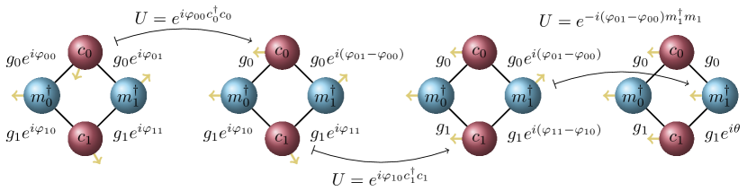
Assuming that both magnon modes couple with the same coupling strength to the cavity mode , the interaction Hamiltonian under the RWA is generalised to
| (12) | ||||
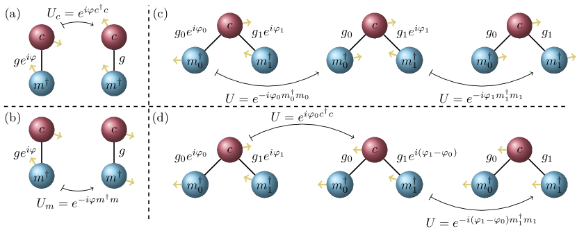
This interaction Hamiltonian can be simplified by focusing all the coupling phases into one term (see fig. 1) using unitary transformations (we recall some elementary properties of unitary transformations in appendix B). The transformed interaction Hamiltonian is
| (13) | ||||
with . The “physical phase” is reminiscent of a discrete Pancharatnam–Berry phase, a gauge-invariant geometrical phase factor originating from the existence of a local gauge degree of freedom for each state involved in a loop in some parameter space [42]. This gauge is nothing but a choice of phase, which in our system is the coupling phase located on the black lines of fig. 1. The various coupling phases are linked to each other through the circles, forming a loop – leading to an observable physical phase .
To conclude this section, we note that most systems studied in the literature consists of single magnon/photon systems, or several magnon modes coupling to a single cavity mode. In particular, setups comprised of two magnon modes coupling to one cavity mode have attracted interest for indirect coupling and dark mode physics [21, 15, 16, 17, 19, 20], as well as the generation of entangled states [43, 44, 45]. In these cases, the coupling phases do not lead to a physical phase, as we show in appendix C. This is in stark contrast with the system proposed here.
IV Influence of the physical phase
We now highlight the -dependent physics of the system described in the previous section, i.e.
| (14) |
with and given by eqs. 9 and 13. While could in principle take any value in , we will focus our analysis on and , differing only in the sign of the coupling strength of the last term.
IV.1 Diagonalisation method
The coupling between the photonic and matter degrees of freedom described by eq. 13 leads to the appearance of quasiparticles known as polaritons. Polaritons are hybridised light/matter states and, in the context of cavity magnonics, they are known as cavity magnon-polaritons (CMP) [46, 3]. Diagonalisation of the system allows one to find the frequencies of the polaritons, as well as their composition in terms of the cavity and magnon mode operators . All the modes of the system being bosonic, diagonalisation can be achieved by writing with (t indicates matrix transposition) and
| (15) |
After diagonalisation of , the eigenvectors give the polaritonic operators , while the eigenvalues give the polaritonic frequencies . The polaritons can be expressed in terms of the initial operators as
| (16) |
where the coefficients () are the first (last) two components of the eigenvectors of .
We note that in general, diagonalising amounts to solving a polynomial equation of degree four, namely
| (17) |
where is the identity matrix. Whilst analytical solutions exist, they are rather unpleasant and do not clarify the physics.
IV.2 Spectrum and cavity-mediated coupling
Spectral features.
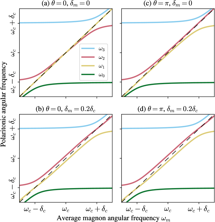
We numerically diagonalised eq. 15 for and in fig. 2. The coherent magnon/photon couplings manifest as two anti-crossings, each located near the resonance of the associated cavity mode (i.e. at ). We observe that the value of the physical phase seems to have an impact only when , since as increases the cases and become less distinguishable.
Interestingly, it appears that when and , the eigenvalues and cross for (fig. 2), but do not for (fig. 2). Repulsion between energy levels is usually the signature of a coupling phenomenon, while level crossing is indicative of the absence of coupling. This suggests that at , the eigenmodes associated with and couple for , but do not for .
Analysis in the dispersive regime.
To clarify this spectral feature, we consider the dispersive regime, where both magnons are assumed to be far detuned from both cavity modes. Defining the detuning between the cavity mode and the magnon mode , the dispersive limit corresponds to for all . Under this approximation, we can employ a Schrieffer-Wolff transformation to perform first-order perturbation theory in (see appendix D). We find that the magnon modes being significantly detuned from the cavity modes, the photon/magnon couplings are negligible, and the cavity and magnon modes decouple from each other (see eq. 57). However, virtual photons still mediate a magnon/magnon interaction, which for , is described by the effective Hamiltonian (again, see appendix D for details)
| (18) | ||||
where the frequencies of the magnons are shifted due to the cavity modes as
| (19) |
and the indirect magnon-magnon coupling is
| (20) |
The magnitude of characterises the strength of the magnon-magnon coupling, and predicts level repulsion of the eigenmodes of eq. 18. However, for and , the magnons do not interact since vanishes, leading to crossing of the energy levels.
Cavity-mediated coupling.
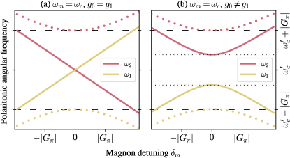
To verify our analysis, we numerically plotted and by diagonalising eq. 15 at in fig. 3. We observe the crossing of the solid lines (corresponding to ), while the dots () anti-cross. The situation changes if we set as shown in fig. 3, and now we observe level repulsion for both and . This behaviour is exactly the one we inferred in the dispersive regime. Note that our analysis of the dispersive regime is valid if . At , this is equivalent to imposing , which the parameters employed in fig. 3 satisfy. Regardless of the values of and , fig. 3 shows that the frequency gap between the eigenmodes of eq. 18 is minimal when , i.e . The location of this minimum gap is given by due to the frequency shift of the magnon modes described by eq. 19.
Physically, eq. 20 highlights an interference effect between the magnon-magnon couplings contributed by each cavity mode. This interference can be constructive for , or destructive for , and we always have . In particular, if , the cavity-mediated coupling between the magnons completely vanishes for . We conclude that the case is always detrimental to indirectly couple two spatially distant magnons, while the case is benificial. This conclusion highlights the importance of the physical phase for multimode cavity-mediated coupling applications.
IV.3 Dark mode physics
Rotated magnon basis.
After having looked at the spectrum, we now turn our attention to the eigenmodes of . The physics will be more easily understood by considering a rotated magnon basis , defined by
| (21) |
It is easy to prove that, since and commute with each other, so do and . Note that corresponds to co-rotating magnons (i.e. both magnons precess in-phase) while corresponds to counter-rotating magnons (precessing out-of-phase). In this basis, the free Hamiltonian eq. 9 now reads
| (22) | ||||
while the interaction Hamiltonian eq. 13 reads
| (23) | ||||
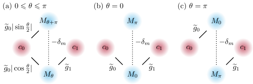
where we introduced the notation . The different interaction pathways between the modes are illustrated in fig. 4.
Notably, if , describes the interaction between four different modes, while for it separates into a 3-mode system and a one-mode system , and for it separates into two two-mode systems and . In particular, for and (fig. 4), we see that does not couple to any other mode.
Dark mode definition.
The presence of such an uncoupled eigenmode is reminiscent of dark mode physics. Dark (bright) states are states that weakly (strongly) couple with the readout mechanism. Due to their weak coupling, these states benefit from an increased lifetime over their bright counterpart, and hence are interesting candidates for storing information. Dark and bright modes are defined similarly, but refer to the associated polaritonic mode in continuous variable systems.
The definition of a dark mode given above is dependent on the mechanism used to probe the system. Since here we are interested in photon/magnon hybridisation, we consider a detection based on a microwave transmission experiment mediated by photons. As a consequence, we expect that any eigenmodes coupling with cavity modes will indirectly couple to the readout medium, hence acquiring an experimental signature.
The input-output formalism [47] allows one to model this scenario. To illustrate our discussion of dark modes, we now consider the transmission through the cavity ( parameter), experimentally obtained by attaching a vector network analyser to the two ports of a cavity. The derivation of the input-output theory is rather lengthy, so we refer the reader to appendix E for more details. We consider that each cavity mode couples to a photonic bath with coupling rate and we set MHz. We further introduce the intrinsic dissipation MHz of the cavity (due to its finite quality factor) and magnon modes (Gilbert damping) through . Other parameters are as in fig. 2. The numerical results are plotted in fig. 5.
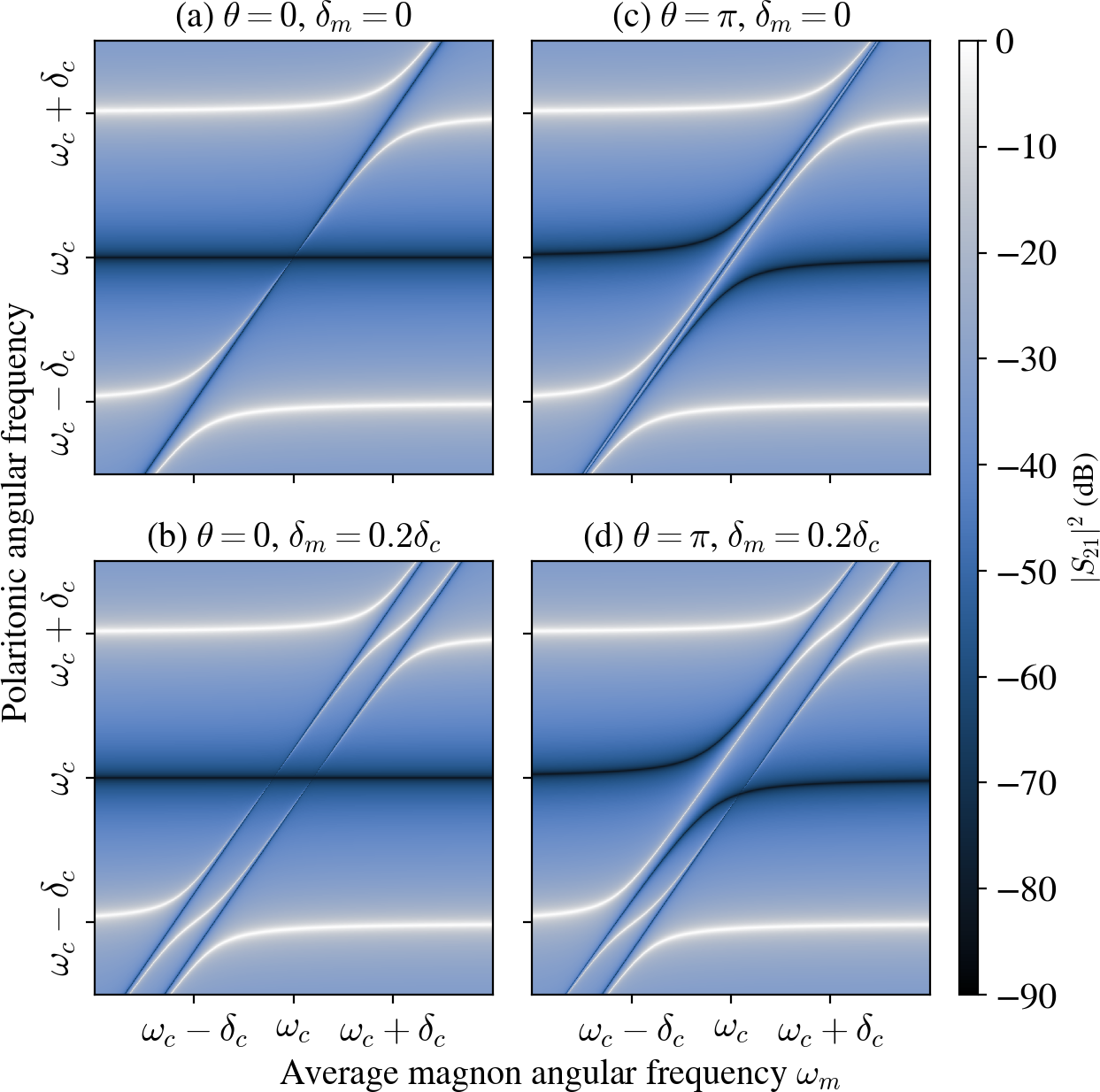
Dark mode physics.
Given the definition of a dark mode given above, we conclude that for , is dark, since it is uncoupled to cavity modes. This is indeed what we observe in fig. 5: comparing to the spectrum in fig. 2, the polaritonic frequency associated with does not give a maximum of transmission, unlike the other frequencies. This is in contrast with fig. 5, in which all the polaritonic frequencies lead to maxima of transmissions. Indeed, for , couples to . Hence, since all the eigenmodes for couple to photons, we conclude that strictly speaking, there are no dark modes for .
These observations rely on both magnons modes having identical resonance frequencies, i.e. . If this symmetry is broken by setting , a new interaction pathway between and opens (see fig. 4), regardless of the value of . Since couples to the cavity modes, then will also couple to the cavity modes through . As a consequence, we expect to acquire an experimental signature if . This theoretical prediction is supported numerically by figs. 5 and 5. We note that this phenomenon of the illumination of a dark mode by symmetry breaking was already discussed by [20] in the interaction picture.
To conclude this section, we comment on the presence of two types of anti-resonances. The first type corresponds to dark diagonal lines which follow the FMR of the YIG spheres. They are the result of destructive interference between the FMR and the RF magnetic mode of the cavity, as explained by [48]. The other type is due to destructive interference between the two cavity modes, and corresponds to the dark horizontal lines centred around . These anti-resonances are uncoupled for (straight line for all ), while for an anti-crossing appears. This phenomenon can be explained by the fact that for , both cavity modes couple to with equal coupling strengths, while the situation is different for (see fig. 4). Had we set , the anti-resonance due to the cavity modes would have also coupled near the FMR for .
V Conclusion
To summarise our results, we showed that the interaction between a microwave photon and a magnon in a cavity is always associated with a coupling phase, which is different from that in dissipatively coupled systems. In most cases studied in the literature, this coupling phase can be omitted because of the simple topology of the interaction diagrams. Indeed, we traced the manifestation of the coupling phase to the presence of loops in the interaction diagrams (as illustrated by fig. 6), a phenomenon similar to a discrete Pancharatnam–Berry phase. To illustrate that the physics was dependent on the coupling phase, we considered a model composed of two cavity modes and two magnon modes, parametrised by the physical phase . For different values of , we found different behaviours with respect to two potential applications of cavity magnonics: one case is advantageous for cavity-mediated coupling but cannot be used for dark mode memories (), and vice-versa for the other case (). We note that while we showed results only for and , our analytical derivations were still parametrised by a general , and hence apply to intermediate cases. In fact, values of between 0 and continuously interpolate between the results presented in this paper (see the cavity-mediated coupling strength of eq. 20 for example).
One could question whether there are simpler models in which there is a physical phase. In theory, any system in which there are interactions between bosonic modes, with one being a microwave photon/magnon interaction, leads to a physical phase. One such example was considered by Zhan et al., where two ferromagnetic bilayers couple to a common cavity mode, but can also directly couple together thanks to the interlayer exchange interaction. This results in a triangular-shaped interaction diagram, so that in principle, a physical phase should parametrise their Hamiltonian. However, it is unclear how the impact of the physical phase could be experimentally verified in such a system. First, achieving different coupling phases for each ferromagnetic bilayers is a challenging experimental task, since the two layers need to be close to each other but be penetrated by the same cavity mode with a different angle (see eq. 5). Furthermore, as noted by the authors of Zhan et al., the experimental verification of their analysis requires smaller magnon damping rates than currently reported in experiments.
Instead, the model introduced in section III should be experimentally accessible using re-entrant cavity designs. Indeed, previous experimental results demonstrated the tunability of the frequencies of the cavity modes, with values of the coupling strengths compatible with the RWA [31, 36, 37]. Placing two YIG spheres in a 3-post re-entrant cavity should allow to implement the two cases and discussed here, and will be the subject of a separate investigation.
The engineering of cavities to achieve specific physical phases is an exciting research direction. The design of such cavities will consists in controlling the relative orientation of the magnetic modes traversing the magnetic samples, as described by eq. 5. Finally, we note that we considered only a rather simple model in which a physical phase manifests. For instance, considering an additional cavity mode would lead to the appearance of two physical phases, for which the physics is yet to explored. More generally, the existence of discrete Pancharatnam–Berry phases in microwave cavity magnonics may find applications in quantum information processing.
Acknowledgements.
We acknowledge financial support from Thales Australia and Thales Research and Technology. We thank Tyler Whittaker, Thomas Kong and Ross Monaghan for reading the manuscript and providing useful comments. The scientific colour map oslo [49] is used in this study to prevent visual distortion of the data and exclusion of readers with colourvision deficiencies [50].Appendix A Photon/magnon coupling term
In this appendix, we show that the interaction term between a microwave cavity mode and a magnon mode can be expressed as
| (24) |
with and positive real numbers. This derivation is valid in the macrospin approximation [32, 33] and provided the number of magnon excitations is small compared to the number of spins.
Our starting point is the supplementary material of ref. [30]. In particular, it is shown that in the macrospin approximation the interaction term is given by
| (25) | ||||
with
| (26) | ||||
| (27) | ||||
| (28) | ||||
| (29) |
where is the gyromagnetic ratio, the volume of the magnetic sample, the volume of the cavity, the resonance of the cavity, the total spin number of the macrospin operator, the magnetic moment of the magnetic sample, the Landé -factor, the Bohr magneton, the number of spins in the magnetic sample, the speed of light in vacuum, the permittivity of vacuum, and the magnetic mode of the cavity.
Assuming that the magnetic mode has no dependence, and eq. 25 can be written as with
| (30) | ||||
| (31) |
where we used and we recognise the quantity defined in eq. 6 of the main text. We introduced as a cavity mode, which means that it is the solution of an eigenvalue problem for the electromagnetic field obeying the Maxwell’s equations in the cavity. By definition, is also a solution to this eigenvalue problem, and hence eq. 31 is still valid after replacing . This removes the inconvenient minus sign eq. 31 so that we can now write
| (32) | ||||
| (33) |
where we defined
| (34) | ||||
| (35) | ||||
| (36) |
as announced in the main text.
To derive the expression of the coupling strength as per the main text, we follow [31] and write with the spin density of the magnetic sample. Equation 33 is then rewritten
| (37) |
with
| (38) |
Appendix B Unitary transformations
A time-dependent unitary transformation maps a Hamiltonian to such that
| (39) |
This corresponds to the so-called rotating frame transformations. For a time-independent unitary transformation, , we simply refer to it as a change of frame. The Baker–Campbell–Hausdorff formula is useful for computing the transformed Hamiltonian, it reads
| (40) |
where and are operators, and we note the -th iterated commutator defined as
| (41) | |||
| (42) |
and so on.
For an annihilation operator following bosonic commutation relation and , the unitary transformation transforms and as
| (43) | ||||
| (44) |
The associated number operator is unaffected by the transformation, since
| (45) | ||||
| (46) |
where since is unitary.
Additionally, for any operator that commutes with , i.e , then is unaffected by the transformation, i.e , due to the vanishing of the iterated commutators in the Baker–Campbell–Hausdorff formula (eq. 40).
Appendix C Relevance of the phase factor
C.1 Removal of the coupling phase for a magnon/photon system
In the simple case of a single cavity mode coupling to a single magnon mode, the Hamiltonian is defined by eqs. 1 and 7. In light of fig. 6, we can
choose to rotate the cavity mode by using . Formally, is unchanged while
| (47) | ||||
| (48) | ||||
| (49) | ||||
| (50) |
hence removing the coupling phase . Pictorially, this is illustrated on the right of fig. 6, where we see that the yellow arrow of mode has changed orientation, and is now pointing in the same direction as that of mode . Alternatively, as illustrated in fig. 6, we can rotate the magnon mode instead, using , which yields the same result, albeit with a different final orientation of the yellow arrows.
The fact that is absent after a change of frame implies that it cannot be physical. Similarly, note that the two extremal cases and differ only by the sign of the coupling strength, and hence we deduce that its polarity does not affect the physics.
C.2 Removal of the coupling phase for two magnons coupling to a common cavity mode
We now assume that an additional magnon mode couples to the cavity mode, as considered in many works [21, 15, 16, 17, 19, 20, 43, 44, 45]. We also note that since all modes are bosonic, this scenario is equivalent to one where a single magnon mode couples to two cavity modes, as considered e.g by [48]. The Hamiltonian is with
| (51) | ||||
| (52) |
One simple possibility to remove the coupling phases is to successively rotate using for (fig. 6). While this is the simplest method, we could also rotate the cavity mode (fig. 6), for instance to remove using , but then the coupling to the second magnon is also affected and reads . Applying removes the remaining phase.
Formally, it appears that the coupling phases are again unimportant for the resulting physics. While the physics is unchanged, we would like to mention that the interpretation of the physics is: the rotated frame is not the laboratory frame. As an example, [20] studied the specific case of and , and found that was the only dark mode of the system. If we were to consider instead (obtained by applying for instance), we would find that the dark mode is transformed to in this frame. Still, the spectrum and other physical predictions of [20] would all hold.
C.3 Two cavity modes and two magnon modes
We note that the removal of the coupling phases in the previous examples was facilitated by the fact that the interaction diagrams had open ends: the rotation of the modes at the ends of the interaction chain would at most affect one edge. Having a closed loop, however, removes this freedom, resulting in an observable physical phase . We believe the hybrid system introduced in section III is the simplest system with an interaction loop involving a magnon/photon interaction, which could be experimentally accessible.
Appendix D Effective Hamiltonian in the dispersive regime
For the purpose of this section, we adopt different notations for convenience. The model studied in the main text can be written as
| (53) | ||||
| (54) |
with , , and . We will hence assume that in this section, even though we will mostly be interested in the cases or , for which the become reals. We also introduce the detuning between the cavity mode and the magnon mode . In the rest of this section, we assume that the magnons are significantly detuned from the both cavity mode such that with for .
To find the effective Hamiltonian in this regime, we employ a Schrieffer-Wolff transformation [51] to treat as a perturbation of . Using the unitary transformation with
| (55) |
we have and the Baker–Campbell–Hausdorff formula (see eq. 40) gives to first order in .
After using commutator identities, we find the commutator
| (56) | ||||
The constant originates from using the bosonic commutation relations for the operators . Hence, after applying , we obtain the effective Hamiltonian
| (57) | ||||
with shifted resonances
| (58) | ||||
| (59) |
photon/photon couplings
| (60) |
and magnon/magnon couplings
| (61) |
The effective Hamiltonian highlights the decoupling of the photonic and matter degrees of freedom in the dispersive regime: light and matter do not interact anymore. However, we obtained a photon/photon coupling mediated by virtual magnons, nad magnon/magnon couplings mediated by virtual photons.
Concentrating on the magnon modes, and setting , we obtain the effective Hamiltonian for the magnons
| (62) |
with and shifted magnon frequencies
| (63) | ||||
| (64) |
Appendix E Details of the input-output theory
In the main text, we consider the transmission of the cavity by microwave photons. In this appendix, we derive an analytical expression of the transmission of the cavity using the input-output formalism [47]. We note that similar results can be obtained employing the loop theory introduced in [52]. In the following, we assume that we have replaced for with the intrinsic dissipation rate.
Bath modelling.
We model the environment with a bosonic bath Hamiltonian with operators and for the left and right side of the cavity. It reads
| (65) |
The interaction between the bath and the cavity is
| (66) |
where we define for the bath operators . The Heisenberg equation of motion for the bath operators is
| (67) |
with the formal solutions
| (68) | ||||
for and
| (69) | ||||
for .
System for the cavity modes in frequency space.
We now define the input fields
| (70) |
and using the solution of eq. 68 for we have
| (71) |
We adopt the notations of appendix D and write the interaction term . The Heisenberg equation for the cavity modes at reads
| (72) | ||||
| (75) |
while that for the magnon modes is
| (76) |
In frequency space,
| (77) |
which gives
| (78) |
At this stage, it is convenient to introduce the detunings
| (79) |
The cavity modes in Fourier space then read
| (80) |
Separating the terms and , we obtain the system
| (81) | ||||
| (82) |
with the solutions
| (83) | ||||
| (84) |
and
| (85) | ||||
| (86) | ||||
| (87) |
Input-output relations.
We now define the output field
| (88) |
and using the solution at we have
| (89) |
which combined with eq. 71 leads to input-output relations
| (90) |
valid for each bath operator .
Transmission.
References
- Zhang et al. [2016] X. Zhang, C.-L. Zou, L. Jiang, and H. X. Tang, Cavity magnomechanics, Science Advances 2, 10.1126/sciadv.1501286 (2016).
- [2] D. Lachance-Quirion, Y. Tabuchi, A. Gloppe, K. Usami, and Y. Nakamura, Hybrid quantum systems based on magnonics, Applied Physics Express 12, 070101.
- [3] M. Harder and C.-M. Hu, Cavity spintronics: An early review of recent progress in the study of magnon–photon level repulsion, Solid State Physics , 47–121.
- Harder et al. [2021] M. Harder, B. M. Yao, Y. S. Gui, and C.-M. Hu, Coherent and dissipative cavity magnonics, Journal of Applied Physics 129, 201101 (2021).
- Rameshti et al. [2021] B. Z. Rameshti, S. V. Kusminskiy, J. A. Haigh, K. Usami, D. Lachance-Quirion, Y. Nakamura, C.-M. Hu, H. X. Tang, G. E. Bauer, and Y. M. Blanter, Cavity magnonics (2021), arXiv:2106.09312 [cond-mat.mes-hall] .
- Zhang et al. [2014] X. Zhang, C.-L. Zou, L. Jiang, and H. X. Tang, Strongly coupled magnons and cavity microwave photons, Physical Review Letters 113, 156401 (2014).
- Bourhill et al. [2016] J. Bourhill, N. Kostylev, M. Goryachev, D. L. Creedon, and M. E. Tobar, Ultrahigh cooperativity interactions between magnons and resonant photons in a YIG sphere, Physical Review B 93, 144420 (2016).
- Goryachev et al. [2014] M. Goryachev, W. G. Farr, D. L. Creedon, Y. Fan, M. Kostylev, and M. E. Tobar, High-cooperativity cavity qed with magnons at microwave frequencies, Phys. Rev. Applied 2, 054002 (2014).
- Golovchanskiy et al. [2021a] I. Golovchanskiy, N. Abramov, V. Stolyarov, A. Golubov, M. Y. Kupriyanov, V. Ryazanov, and A. Ustinov, Approaching deep-strong on-chip photon-to-magnon coupling, Phys. Rev. Applied 16, 034029 (2021a).
- Golovchanskiy et al. [2021b] I. A. Golovchanskiy, N. N. Abramov, V. S. Stolyarov, M. Weides, V. V. Ryazanov, A. A. Golubov, A. V. Ustinov, and M. Y. Kupriyanov, Ultrastrong photon-to-magnon coupling in multilayered heterostructures involving superconducting coherence via ferromagnetic layers, Science Advances 7, 10.1126/sciadv.abe8638 (2021b).
- Bourcin et al. [2022] G. Bourcin, J. Bourhill, V. Vlaminck, and V. Castel, Strong to ultra-strong coherent coupling measurements in a yig/cavity system at room temperature, (2022), arXiv:2209.14643 [quant-ph] .
- Hyde et al. [2016] P. Hyde, L. Bai, M. Harder, C. Match, and C.-M. Hu, Indirect coupling between two cavity modes via ferromagnetic resonance, Applied Physics Letters 109, 152405 (2016).
- Crescini et al. [2021] N. Crescini, C. Braggio, G. Carugno, A. Ortolan, and G. Ruoso, Coherent coupling between multiple ferrimagnetic spheres and a microwave cavity at millikelvin temperatures, Physical Review B 104, 064426 (2021).
- An et al. [2022] K. An, R. Kohno, A. Litvinenko, R. Seeger, V. Naletov, L. Vila, G. de Loubens, J. B. Youssef, N. Vukadinovic, G. Bauer, A. Slavin, V. Tiberkevich, and O. Klein, Bright and dark states of two distant macrospins strongly coupled by phonons, Physical Review X 12, 011060 (2022).
- [15] N. J. Lambert, J. A. Haigh, S. Langenfeld, A. C. Doherty, and A. J. Ferguson, Cavity-mediated coherent coupling of magnetic moments, Physical Review A 93, 021803.
- Rameshti and Bauer [2018] B. Z. Rameshti and G. E. W. Bauer, Indirect coupling of magnons by cavity photons, Physical Review B 97, 014419 (2018).
- Grigoryan and Xia [2019] V. L. Grigoryan and K. Xia, Cavity-mediated dissipative spin-spin coupling, Physical Review B 100, 014415 (2019).
- [18] P.-C. Xu, J. W. Rao, Y. S. Gui, X. Jin, and C.-M. Hu, Cavity-mediated dissipative coupling of distant magnetic moments: Theory and experiment, Physical Review B 100, 094415.
- Zhan et al. [2021] X. Zhan, Y. Zhang, X. Yan, and Y. Xiao, Bright and dark modes of exchange-coupled ferromagnetic bilayers in a microwave cavity, Journal of Applied Physics 130, 123901 (2021).
- Nair et al. [2022] J. M. P. Nair, D. Mukhopadhyay, and G. S. Agarwal, Cavity-mediated level attraction and repulsion between magnons, Physical Review B 105, 214418 (2022).
- Zhang et al. [a] X. Zhang, C.-L. Zou, N. Zhu, F. Marquardt, L. Jiang, and H. X. Tang, Magnon dark modes and gradient memory, Nature Communications 6, 10.1038/ncomms9914 (a).
- Tabuchi et al. [2015] Y. Tabuchi, S. Ishino, A. Noguchi, T. Ishikawa, R. Yamazaki, K. Usami, and Y. Nakamura, Coherent coupling between a ferromagnetic magnon and a superconducting qubit, Science 349, 405 (2015).
- [23] Y. Tabuchi, S. Ishino, A. Noguchi, T. Ishikawa, R. Yamazaki, K. Usami, and Y. Nakamura, Quantum magnonics: The magnon meets the superconducting qubit, Comptes Rendus Physique 17, 729, quantum microwaves / Micro-ondes quantiques.
- Yuan et al. [2022] H. Yuan, Y. Cao, A. Kamra, R. A. Duine, and P. Yan, Quantum magnonics: When magnon spintronics meets quantum information science, Physics Reports 965, 1 (2022).
- Liu et al. [2019] Z.-X. Liu, H. Xiong, and Y. Wu, Magnon blockade in a hybrid ferromagnet-superconductor quantum system, Physical Review B 100, 134421 (2019).
- kun Xie et al. [2020] J. kun Xie, S. li Ma, and F. li Li, Quantum-interference-enhanced magnon blockade in an yttrium-iron-garnet sphere coupled to superconducting circuits, Physical Review A 101, 042331 (2020).
- Wu et al. [2021] K. Wu, W. xue Zhong, G. ling Cheng, and A. xi Chen, Phase-controlled multimagnon blockade and magnon-induced tunneling in a hybrid superconducting system, Physical Review A 103, 052411 (2021).
- Lachance-Quirion et al. [2020] D. Lachance-Quirion, S. P. Wolski, Y. Tabuchi, S. Kono, K. Usami, and Y. Nakamura, Entanglement-based single-shot detection of a single magnon with a superconducting qubit, Science 367, 425 (2020).
- Wolski et al. [2020] S. Wolski, D. Lachance-Quirion, Y. Tabuchi, S. Kono, A. Noguchi, K. Usami, and Y. Nakamura, Dissipation-based quantum sensing of magnons with a superconducting qubit, Physical Review Letters 125, 117701 (2020).
- [30] G. Flower, M. Goryachev, J. Bourhill, and M. E. Tobar, Experimental implementations of cavity-magnon systems: from ultra strong coupling to applications in precision measurement, New Journal of Physics 21, 095004.
- [31] J. Bourhill, V. Castel, A. Manchec, and G. Cochet, Universal characterization of cavity–magnon polariton coupling strength verified in modifiable microwave cavity, Journal of Applied Physics 128, 073904.
- Soykal and Flatté [a] O. O. Soykal and M. E. Flatté, Size dependence of strong coupling between nanomagnets and photonic cavities, Physical Review B 82, 104413 (a).
- Soykal and Flatté [b] O. O. Soykal and M. E. Flatté, Strong field interactions between a nanomagnet and a photonic cavity, Phys. Rev. Lett. 104, 077202 (b).
- Stancil and Prabhakar [2009] D. D. Stancil and A. Prabhakar, Spin Waves (Springer US, 2009).
- Holstein and Primakoff [1940] T. Holstein and H. Primakoff, Field dependence of the intrinsic domain magnetization of a ferromagnet, Phys. Rev. 58, 1098 (1940).
- Carvalho et al. [2016] N. C. Carvalho, Y. Fan, and M. E. Tobar, Piezoelectric tunable microwave superconducting cavity, Review of Scientific Instruments 87, 094702 (2016).
- Tobar and Goryachev [2019] M. E. Tobar and M. Goryachev, Microwave frequency magnetic field manipulation systems and methods and associated application instruments, apparatus and system (2019).
- Forn-Díaz et al. [2019] P. Forn-Díaz, L. Lamata, E. Rico, J. Kono, and E. Solano, Ultrastrong coupling regimes of light-matter interaction, Reviews of Modern Physics 91, 025005 (2019).
- Frisk Kockum et al. [2019] A. Frisk Kockum, A. Miranowicz, S. De Liberato, S. Savasta, and F. Nori, Ultrastrong coupling between light and matter, Nature Reviews Physics 1, 19–40 (2019).
- Le Boité [2020] A. Le Boité, Theoretical methods for ultrastrong light–matter interactions, Advanced Quantum Technologies 3, 1900140 (2020), https://onlinelibrary.wiley.com/doi/pdf/10.1002/qute.201900140 .
- Wang and Hu [2020] Y.-P. Wang and C.-M. Hu, Dissipative couplings in cavity magnonics, Journal of Applied Physics 127, 130901 (2020).
- Resta [2000] R. Resta, Manifestations of berry’s phase in molecules and condensed matter, Journal of Physics: Condensed Matter 12, R107 (2000).
- [43] J. Li and S.-Y. Zhu, Entangling two magnon modes via magnetostrictive interaction, New Journal of Physics 21, 085001.
- Zhang et al. [b] Z. Zhang, M. O. Scully, and G. S. Agarwal, Quantum entanglement between two magnon modes via kerr nonlinearity driven far from equilibrium, Physical Review Research 1, 023021 (b).
- Nair and Agarwal [2020] J. M. P. Nair and G. S. Agarwal, Deterministic quantum entanglement between macroscopic ferrite samples, Applied Physics Letters 117, 084001 (2020).
- Harder et al. [2016] M. Harder, L. Bai, C. Match, J. Sirker, and C. Hu, Study of the cavity-magnon-polariton transmission line shape, Science China Physics, Mechanics & Astronomy 59, 10.1007/s11433-016-0228-6 (2016).
- Gardiner and Collett [1985] C. W. Gardiner and M. J. Collett, Input and output in damped quantum systems: Quantum stochastic differential equations and the master equation, Physical Review A 31, 3761 (1985).
- [48] M. Harder, P. Hyde, L. Bai, C. Match, and C.-M. Hu, Spin dynamical phase and antiresonance in a strongly coupled magnon-photon system, Physical Review B 94, 054403.
- Crameri [2021] F. Crameri, Scientific colour maps (2021).
- Crameri et al. [2020] F. Crameri, G. E. Shephard, and P. J. Heron, The misuse of colour in science communication, Nature Communications 11, 10.1038/s41467-020-19160-7 (2020).
- Schrieffer and Wolff [1966] J. R. Schrieffer and P. A. Wolff, Relation between the anderson and kondo hamiltonians, Physical Review 149, 491 (1966).
- Yuan et al. [2020] H. Y. Yuan, W. Yu, and J. Xiao, Loop theory for input-output problems in cavities, Physical Review A 101, 043824 (2020).