Manipulating chiral-spin transport with ferroelectric polarization 00footnotetext: ∗ E-mail: xzchen@berkeley.edu, rramesh@berkeley.edu
Present and permanent address of Olle Heinonen: Seagate Technology, 7801 Computer Avenue, Bloomington MN 55435
Abstract
A collective excitation of the spin structure in a magnetic insulator can transmit spin-angular momentum with negligible dissipation
[1, 2, 3, 4, 5]
. This quantum of a spin wave, introduced more than nine decades ago
[6]
, has always been manipulated through magnetic dipoles
[7, 8, 9, 10]
, (i.e., time-reversal symmetry). Here, we report the experimental observation of chiral-spin transport in multiferroic BiFeO3, where the spin transport is controlled by reversing the ferroelectric polarization (i.e., spatial inversion symmetry). The ferroelectrically controlled magnons produce an unprecedented ratio of up to 18% rectification at room temperature. The spin torque that the magnons in BiFeO3 carry can be used to efficiently switch the magnetization of adjacent magnets, with a spin-torque efficiency being comparable to the spin Hall effect in heavy metals. Utilizing such a controllable magnon generation and transmission in BiFeO3, an all-oxide, energy-scalable logic is demonstrated composed of spin-orbit injection, detection, and magnetoelectric control. This observation opens a new chapter of multiferroic magnons and paves an alternative pathway towards low-dissipation nanoelectronics.
Intense studies of spin current transport in magnetic insulators [4, 11, 12, 13, 14] have opened various avenues for research on spintronics [15, 16, 17, 18, 19, 20, 21] and their potential use in low-power applications [13] . This trend has also triggered renewed interest in magnon physics, which can be controlled via time-reversal-symmetry design (e.g., magnetic domain walls [7] , spin Hall currents [8, 9] , static magnetic fields [10] ). On the other hand, recent works have shown that broken inversion symmetry and the resulting Dzyaloshinskii-Moriya interaction (DMI) have profound influence on magnon transport in non-centrosymmetric magnets [22, 23, 24] . In this spirit, multiferroics are potentially of great interest, since they display broken inversion symmetry and a ferroelectric polarization that can be switched by the application of an electric field, which in turn allows for control of the magnetism and, potentially, the magnons. The idea that multiferroics could be promising candidates for magnonic manipulation has been considered for some time [13, 25] , but despite this early interest, observation and manipulation of magnon transport in multiferroics - that is, the capability to manipulate spin transport via ferroelectric polarization reversal and resultant DMI switching- remain elusive.
Here, we demonstrate non-volatile, bistable spin transport in multiferroic BiFeO3 upon reversing the ferroelectric polarization. BiFeO3 is a model multiferroic that exhibits multiple order parameters (i.e., antiferromagnetism and ferroelectricity) and intrinsic magnetoelectric coupling of these coexisting order parameters [26, 27] . In the bulk, BiFeO3 possesses a rhombohedrally distorted perovskite structure in which a spin cycloid [28] is formed with a period length of 64 nm [29, 30] and a Néel temperature of 643 K [31] . The DMI in BiFeO3 thin films can influence the spin cycloid order [32, 33, 13] . At the same time, BiFeO3 thin films possess robust ferroelectricity, with a Curie temperature 1100 K and a large polarization 90 C/cm2 [34] . In turn, BiFeO3 exhibits outstanding magnetoelectric properties which have made it the focus of numerous studies hoping to utilize it as a platform to achieve low-energy (low-voltage) memory devices (e.g., deterministic switching of adjacent ferromagnets [35] ). Specifically, achieving control over changing the magnetization states through ferroelectric polarization switching has always been a keen pursuit in these studies.
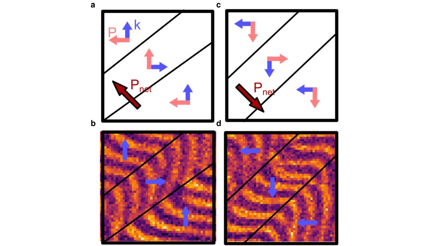
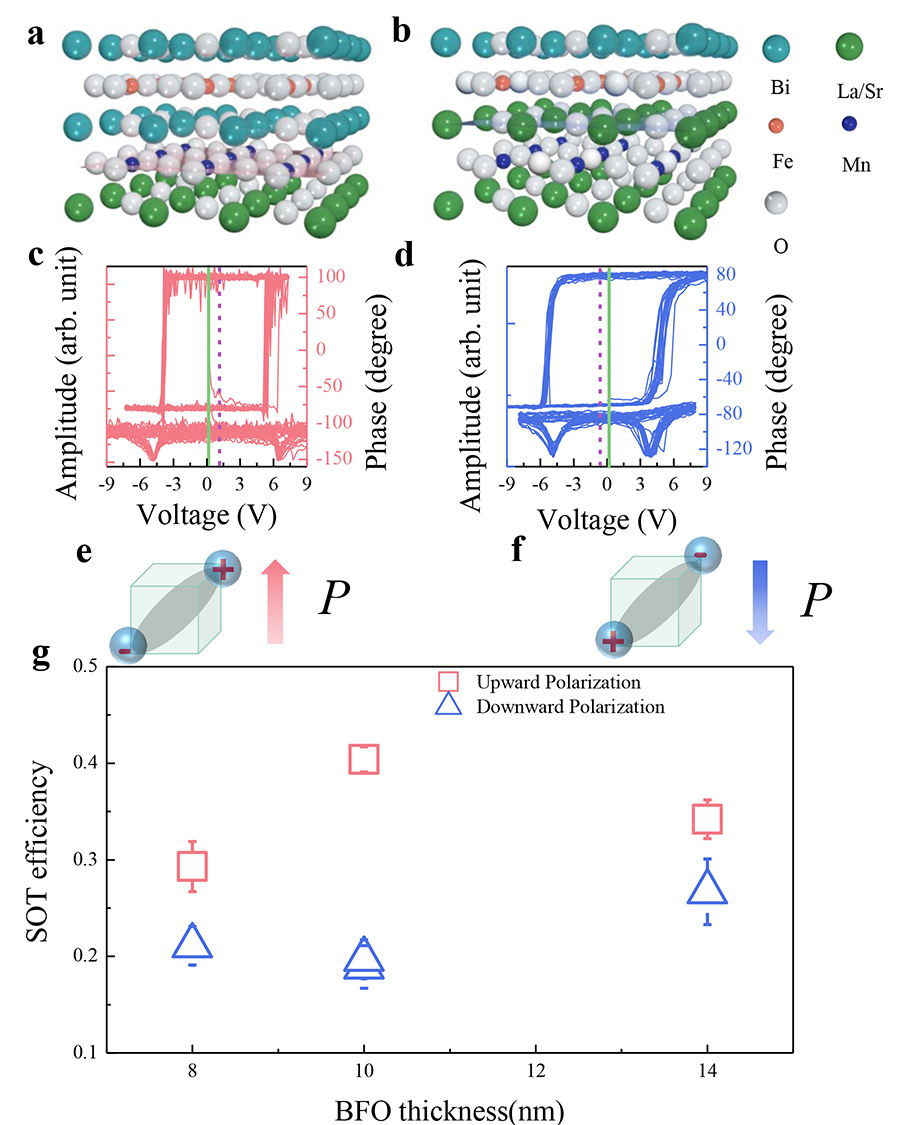
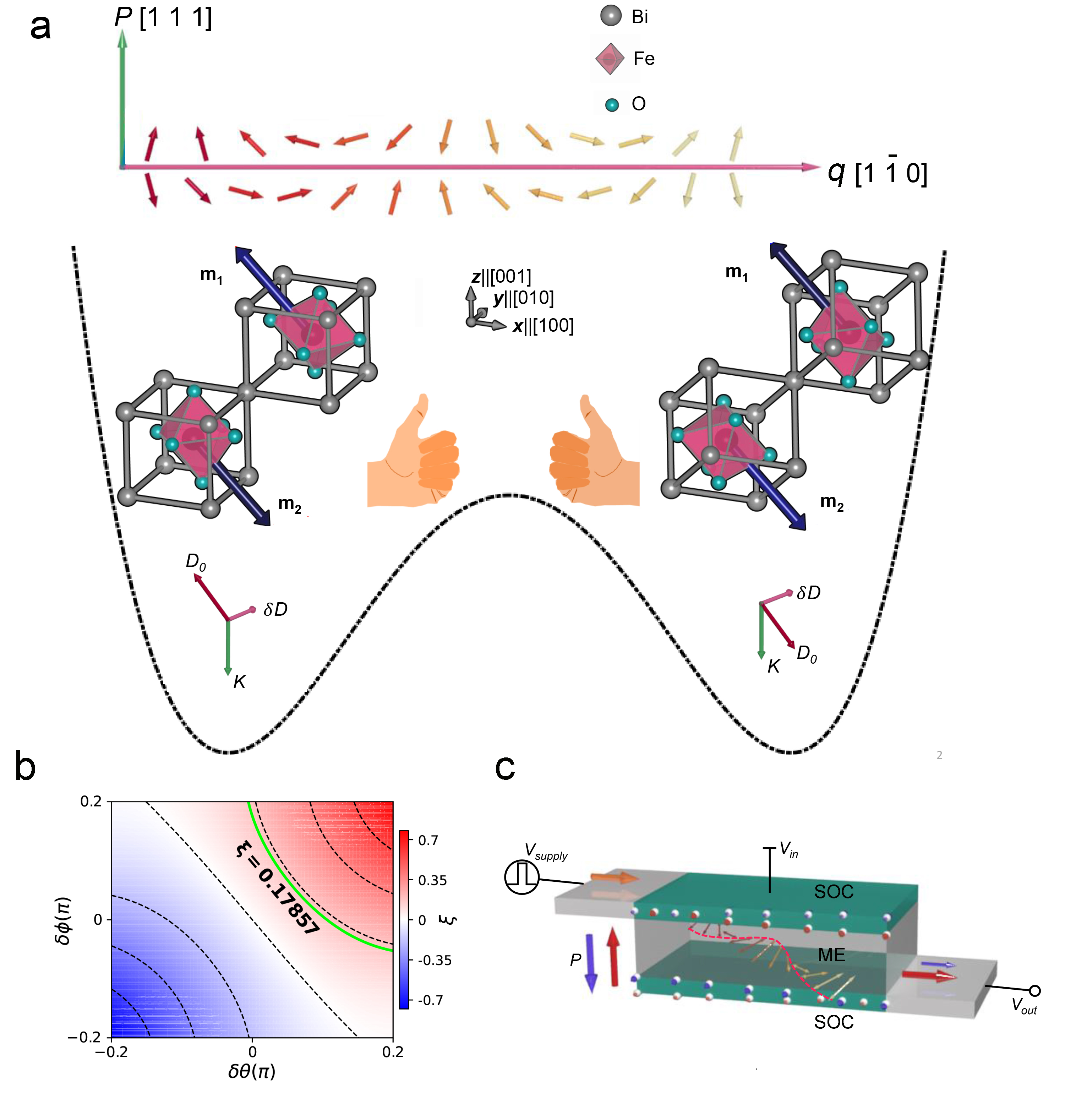
As illustrated in Fig. 1a, a spin cycloid propagating along is revealed by Nitrogen-Vacancy diamond magnetometry measurements ( Extended Data Fig. 1), which is in good agreement with the pioneering work of Gross et al [29, 30] . The formation of spin cycloid has been explained in terms of a Lifshitz-like invariant [36] which, in the continuum limit, amounts to an effective DMI vector perpendicular to both the ferroelectric polarization (along ) and the spin cycloid propagating direction . In BiFeO3, there is another intrinsic DMI characterized by a global DMI vector parallel to , which is responsible for the small magnetization everywhere perpendicular to the Néel vector . Previous studies have confirmed that the latter mechanism is much weaker so that the spin texture is dominated by [36, 37] . A reversal of is accompanied by the reversal of the octahedral antiphase tilts [35] , which in turn flips the direction of [33, 36] . In addition, the asymmetric gates, the existence of ferroelectric domain walls [38] , and other asymmetries of external origins generate a built-in potential that induces an additional DMI vector , which remains the same under the reversal of . Consequently, the total DMI vector undergoes a non- switching, leading to a slight rotation of the propagation direction . To intuitively understand the ferroelectric control of magnon spin current, we define the hybrid product where is the magnon wave vector (in the thickness direction). It is well-known that the nonreciprocal propagation is allowed not only in magnons but also electrons, electromagnetic waves when they go through materials such as multiferroic materials that host broken time reversal and space inversion symmetry simultaneously. As illustrated in Fig. 1a, reversing necessarily flips the sign of , hence the chirality of these three vectors. This hybrid product can also reflect a directional non-reciprocity where the wave vector flips sign [39, 22, 23, 24] while the DMI is kept unchanged. In other words, this single quantity captures the common feature of both directional non-reciprocity and ferroelectric modulation of the magnon spin current.
Because the thickness of BiFeO3 is much smaller than the spacial period (64 nm) of the spin cycloid, we can ignore any spin texture or magnetic inhomogeneity along the magnon wave vector . Then, the transmitted spin current can be phenomenologically expressed as[15]
| (1) |
where () is the phenomenological spin conductance of the Néel vector (total magnetization), is the polarization of spin injection from the top gate and is the area of the film. As mentioned above, when the total DMI vector undergoes a non- switching, the spin cycloid profile functions and are modulated by in a non-trivial way. As calculated in the Supplemental Materials, the resulting spin current can be substantially different before and after the reversal of . To quantify this difference, we define the rectification ratio as
| (2) |
and plot it against the orientation of the extrinsic relative to the intrinsic (along ) in Fig. 1b, where we have marked the experimental value (to be explained below) .
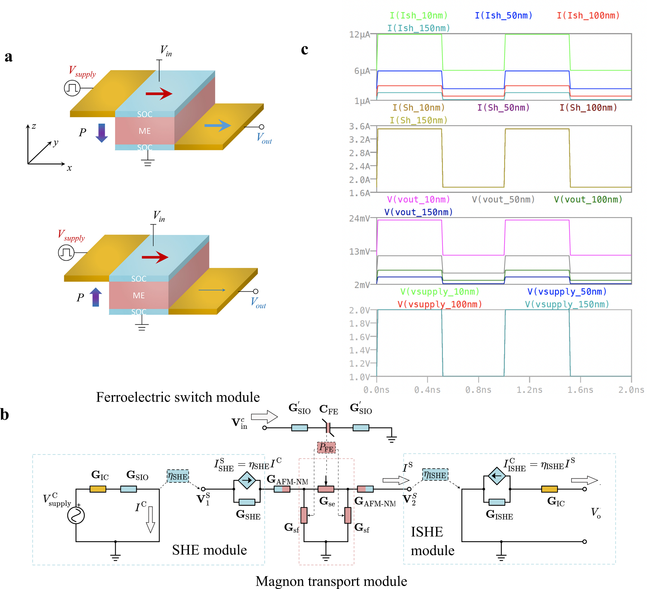
Based on the predicted potential for chiral-magnon control in BiFeO3, a demonstration of a scalable magnetoelectric spin-orbit logic was investigated. A schematic of this idea is illustrated in Fig. 1d. An electric field is set up in the magnetoelectric capacitor in the direction, resulting in the vertical component of the ferroelectricity switching from the to the direction. To read the polarization state, a supply voltage is applied into the top spin-orbit coupled (SOC) channel (e.g., SrIrO3 which has a relatively large spin Hall angle [40] ) in the direction, causing the excitation of magnons in the BiFeO3 via the spin current from the SOC material. The readout of the state of the switch is then enabled by the inverse spin Hall effect using SrIrO3 [41] , where the current direction is along the direction. Owing to the magnon propagation with bistable rectification, the output voltage could acquire two stable states, rendering the buffer function of a logic gate. Especially, as compared with the first magneto-electric, spin-orbit (MESO) device proposal [42] , this design makes use of antiferromagnetic magnon to gauge the antiferromagnetism inside the multiferroic itself instead of relying on the adjacent ferromagnet coupled to the multiferroic ( Extended Data Fig. 2). Early efforts on the elimination of the ferromagnet have been devoted to the electric-field controlled spin-orbit interaction [43, 44] , e.g. Rashba effect in two-dimensional electron gas systems [45, 46] . The elimination of the ferromagnet simplifies the readout architecture; furthermore, the implementation of antiferromagnets can favor ultrafast operations frequency up to THz.
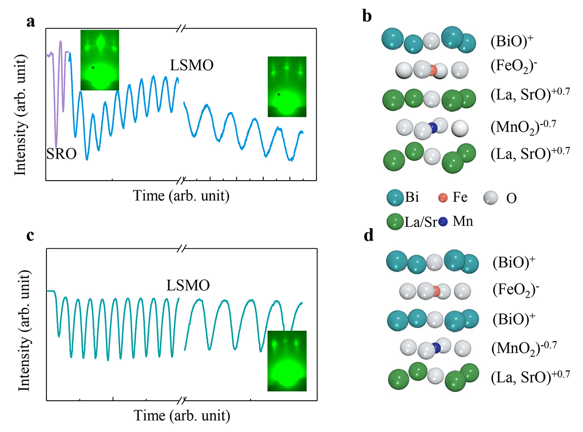
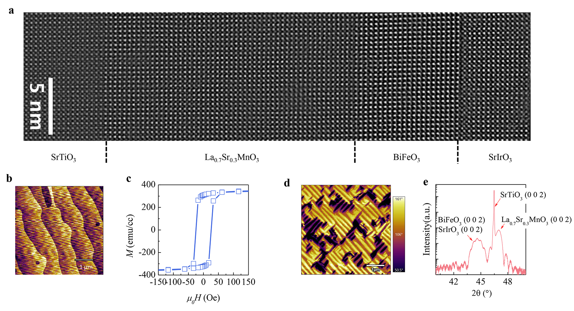
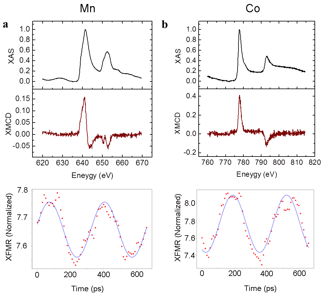
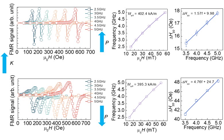
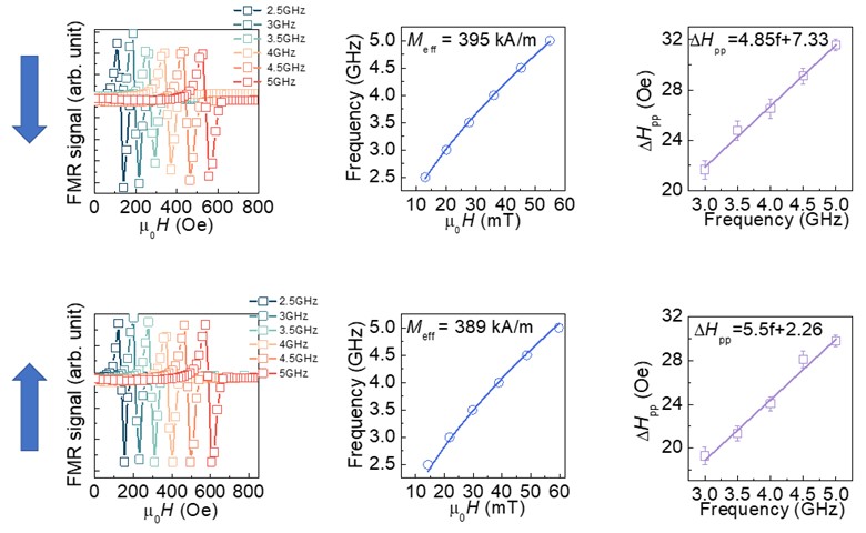
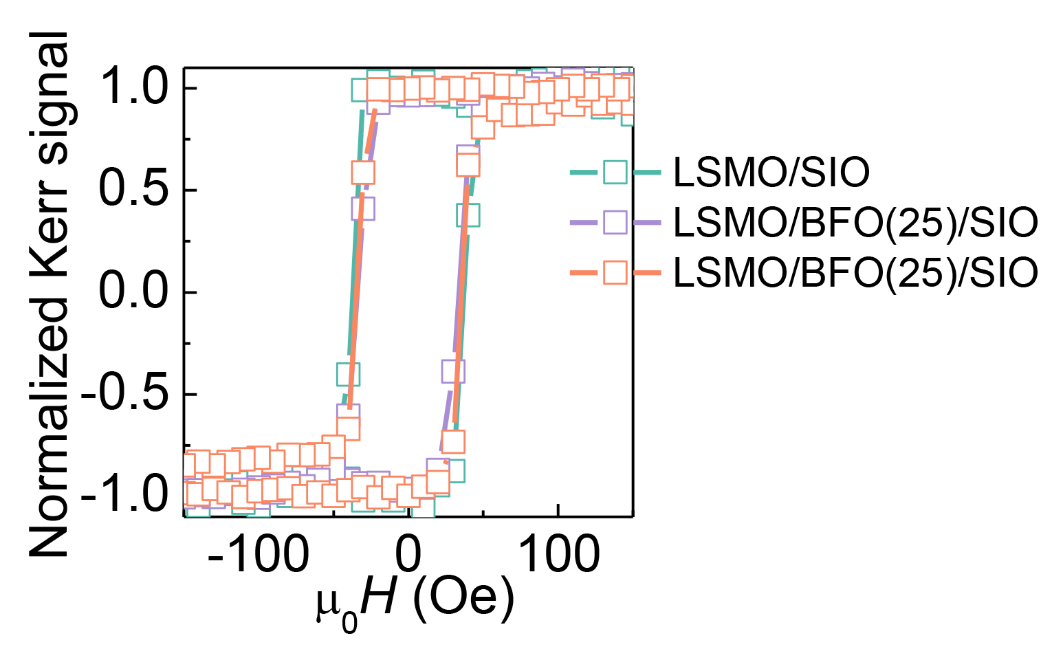
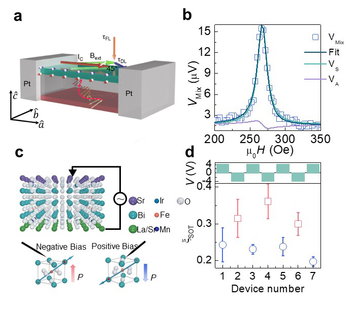
To experimentally explore the controllable spin transmission enabled by the ferroelectric switch in BiFeO3, we first characterized the strength of spin transmission via magnons in the heterostructures of the form La0.7Sr0.3MnO3/BiFeO3 /SrIrO3 (Methods, Extended Data Fig. 3,4). We performed the measurement using a well-established technique namely spin-torque ferromagnetic resonance (ST-FMR) [40, 47] (Fig. 2a), launching the spin current using the large spin Hall effect of SrIrO3 and detecting the spin torque applied to the magnetic La0.7Sr0.3MnO3 layer [48] . An example ST-FMR spectrum, composed of both symmetric and anti-symmetric components, is shown (Fig. 2b) and indicates the successful detection of the spin currents carried by magnons through the BiFeO3. To manipulate the orientation of the ferroelectric polarization, an external electric field was applied along the out-of-plane to set the ferroelectric polarization of the BiFeO3 as illustrated (top panel, Fig. 2c, in which the top SrIrO3 and bottom La0.7Sr0.3MnO3 layers serve as the two electrodes sandwiching the ferroelectric). Specifically, upward- (downward-) pointing polarization ( switching) can be achieved by applying negative (positive) voltage larger than the coercivity of the BiFeO3 on the top SrIrO3 layer (bottom panel, Fig. 2c) [41] . After poling the BiFeO3 in each individual device to the desired polarization state, we then deposited platinum contacts onto the devices (contacting both the SrIrO3 and La0.7Sr0.3MnO3 layers) and performed ST-FMR measurements on the poled devices. By adopting an established analysis method (Methods), the SOT efficiency for the damping-like (DL) torque (symmetric component) is evaluated and summarized (Fig. 2d). We observe that the SOT efficiency can be set at a high value by negative (upward polarization) or at a low value by positive (downward polarization) voltages, indicating the presence of bistable high/low spin transport in BiFeO3. This polarization-dependent spin transmission of BiFeO3 is also verified by interfacial engineering ( Extended Data Fig. 5), time-resolved X-ray ferromagnetic resonance ( Extended Data Fig. 6) and FMR measurements ( Extended Data Fig. 7, 8). The blocking temperature of exchange bias between La0.7Sr0.3MnO3 and BiFeO3 is well below room temperature [49] , and the absence of exchange bias is also confirmed by our magneto-optic Kerr effect measurements ( Extended Data Fig. 9), ruling out the possible contribution from exchange bias on the tuning of spin transmission. It is worthwhile to note that the stability of the ferroelectric polarization reveals another crucial advantage associated with spintronics produced in this manner – non-volatility. By setting the polarization direction, high and low SOT efficiencies of and can be achieved, showing a high/low ratio of approximately %. Furthermore, the ferroelectric polarization controlled spin transmission in BiFeO3 is confirmed by ST-FMR measurements on samples with opposite polarizations set by different interface terminations [50] (Extended Data Fig. 5). This is consistent with our theoretical predictions that the polarization state influences magnon propagation and a spin transmission modulation can be achieved upon ferroelectric polarization switching. Further, from the aforementioned experiments it can be inferred that the spin transmission is favorable when the magnon wave vector is anti-parallel to the z-component of the polarization .
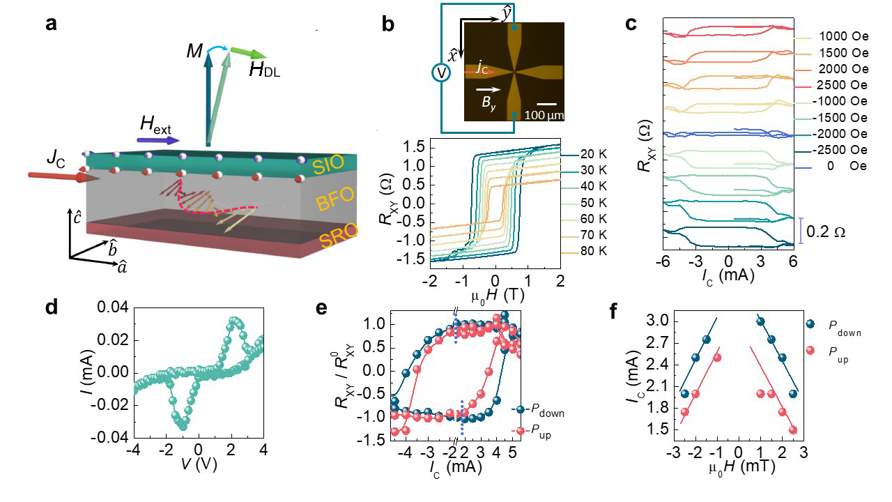
To corroborate the presence of a magnon transmission modulation in BiFeO3, magnetization switching experiments were carried out to serve as a direct demonstration of the strength of the spin torques under ferroelectric polarization modulation. Here, we investigate deterministic magnetization switching of a SrRuO3 layer with perpendicular magnetic anisotropy (PMA) by the spin torque carried by the BiFeO3. Current-induced magnetization switching measurements were carried out for SrRuO3 ( nm)/BiFeO3 ( nm)/SrIrO3 ( nm) heterostructure with BiFeO3 polarized to either upward or downward orientations (Fig. 3a). The switching schematic is also demonstrated (Fig. 3a), where the magnetic moment of the ferromagnetic SrRuO3 is switched between positive and negative directions consistently and reversibly. The magnetic switching was detected by the anomalous Hall effect in the SrRuO3 layer, in which magnetic moments lying on the positive and negative directions can be distinguished by positive and negative values of anomalous Hall resistance. By sweeping an external magnetic field in the out-of-plane direction (Fig. 3b), a hysteretic loop is developed for anomalous Hall resistance (), when the external magnetic field exceeds the coercivity of SrRuO3(Fig. 3b). Furthermore, as a function of magnetic field was repeated at temperatures from K to K, confirming the high quality of our heterostructure, and no shift in the hysteretic loop with respect to zero magnetic field is observed, indicating the absence of exchange bias effect between ferromagnetic SrRuO3 and antiferromagnetic BiFeO3. Then magnetization switching measurements were performed in the same device, and as a function of current pulses was recorded. Notably, a switching of magnetization was observed by both positive and negative currents, when the magnitudes of current pulses exceed the magnitude of critical switching current, and a saturation of is observed with large current pulses, excluding the possible participation of thermal effects in the switching measurements. Moreover, no magnetization switching is observed at zero assisting magnetic field and the switching chirality can be changed by the reversal of polarity of assisting magnetic fields, ruling out the possibility that the magnetization switching is caused by current-induced Oersted field. To further corroborate our observation of ferroelectric polarization-controlled spin transport with ST-FMR, ferroelectric polarization-dependent magnetization switching measurements were carried out. To start with, the polarization of BiFeO3 was switched to either an upward or downward orientation by an external electric field. An example IV curve during the ferroelectric polarization switching measurements is displayed in Fig. 3d, in which the switching of ferroelectric polarization is associated with current peaks in Fig. 3d. Then, the same magnetization switching measurements were conducted on devices with distinct ferroelectric polarization states. A typical switching loop for heterostructures with upward (downward) polarization is displayed in red (blue) solid spheres in Fig. 3e. Strikingly, distinct critical switching currents for upward and downward polarization were observed in both positive and negative current directions. The critical switching currents at different assisting magnetic fields for upward and downward polarization are summarized in Fig. 3f, where upward polarization shows a smaller switching current than downward polarization statistically. Therefore, two conclusions can be drawn based on our experimental observations. First, BiFeO3 has the capability to carry spin information via antiferromagnet magnons, and the spin torque arising from BiFeO3 is sufficiently efficient to switch the magnetization of SrRuO3. More importantly, the spin transmission in BiFeO3 is controlled by ferroelectric polarization, and the smaller critical switching current density for the upward polarization corresponds to a higher spin transmission, in good agreement with the ferroelectric polarization controlled-SOT efficiency study with the ST-FMR technique. The current-induced magnetization switching measurements reinforce the idea that the upward polarization is favorable for magnon transmission.
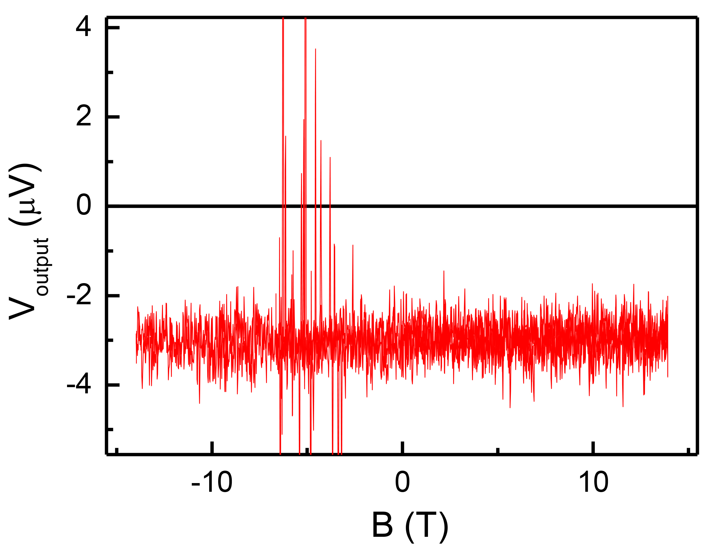
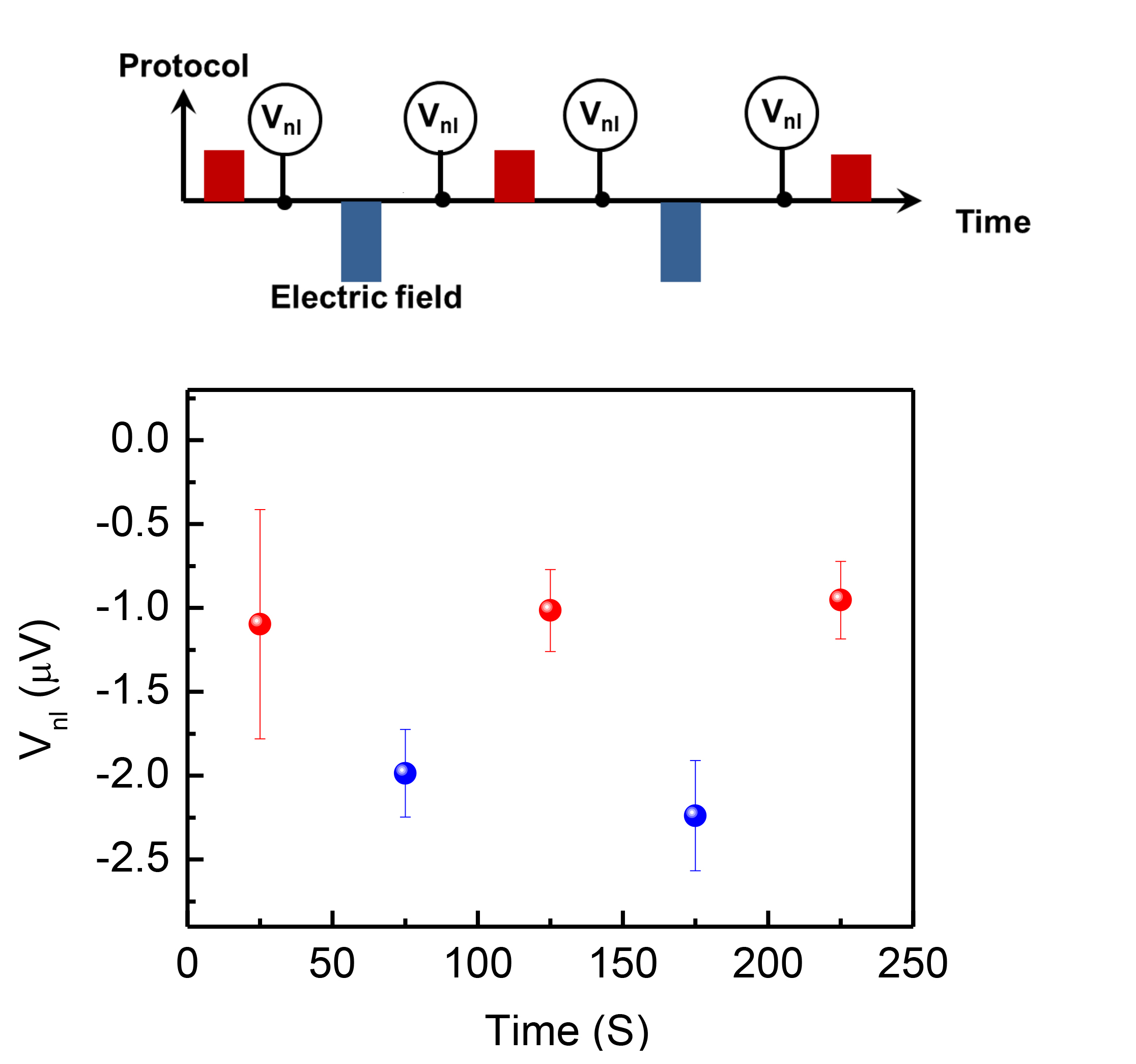
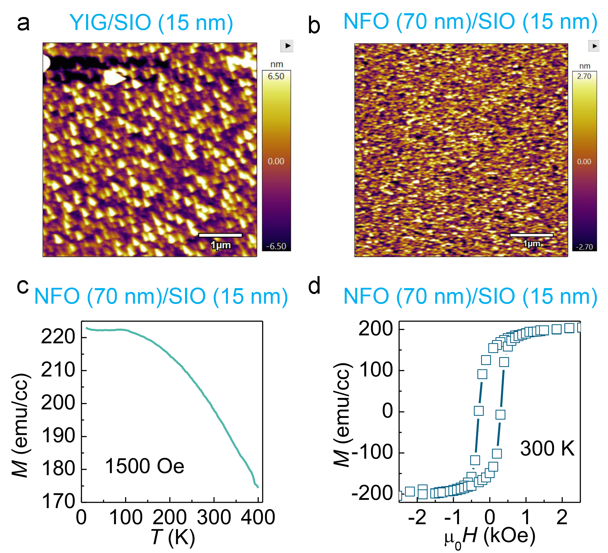
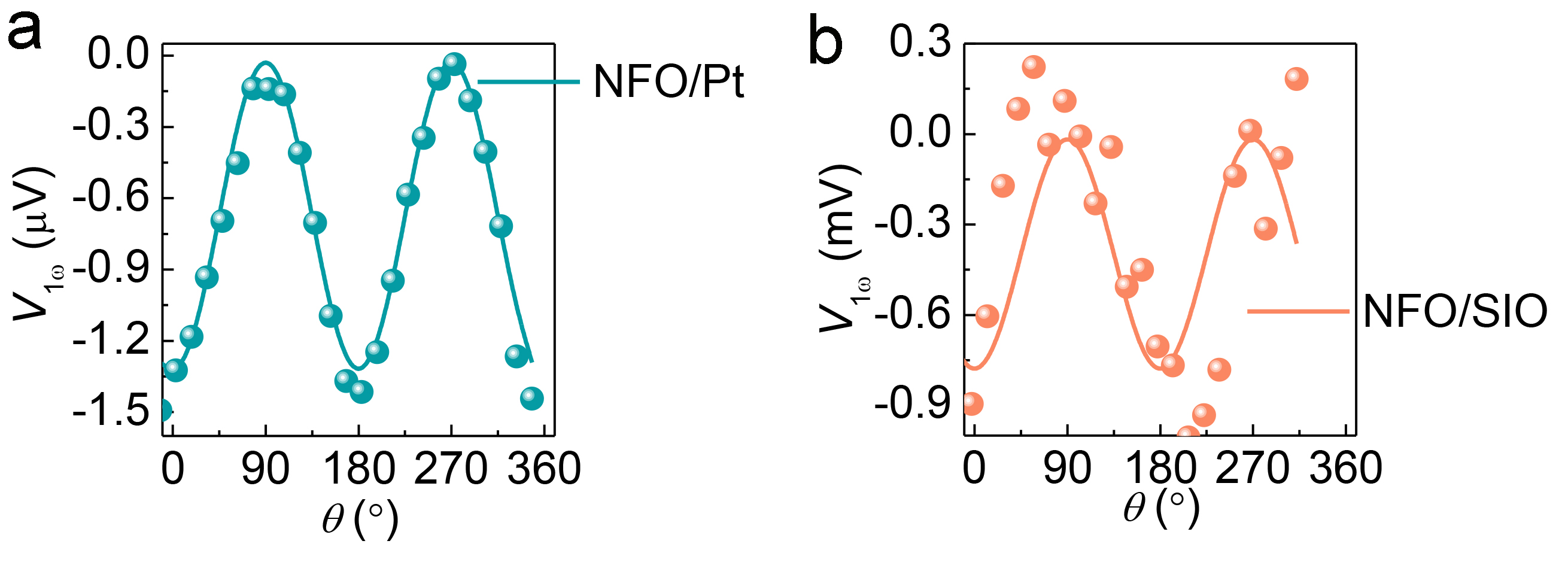
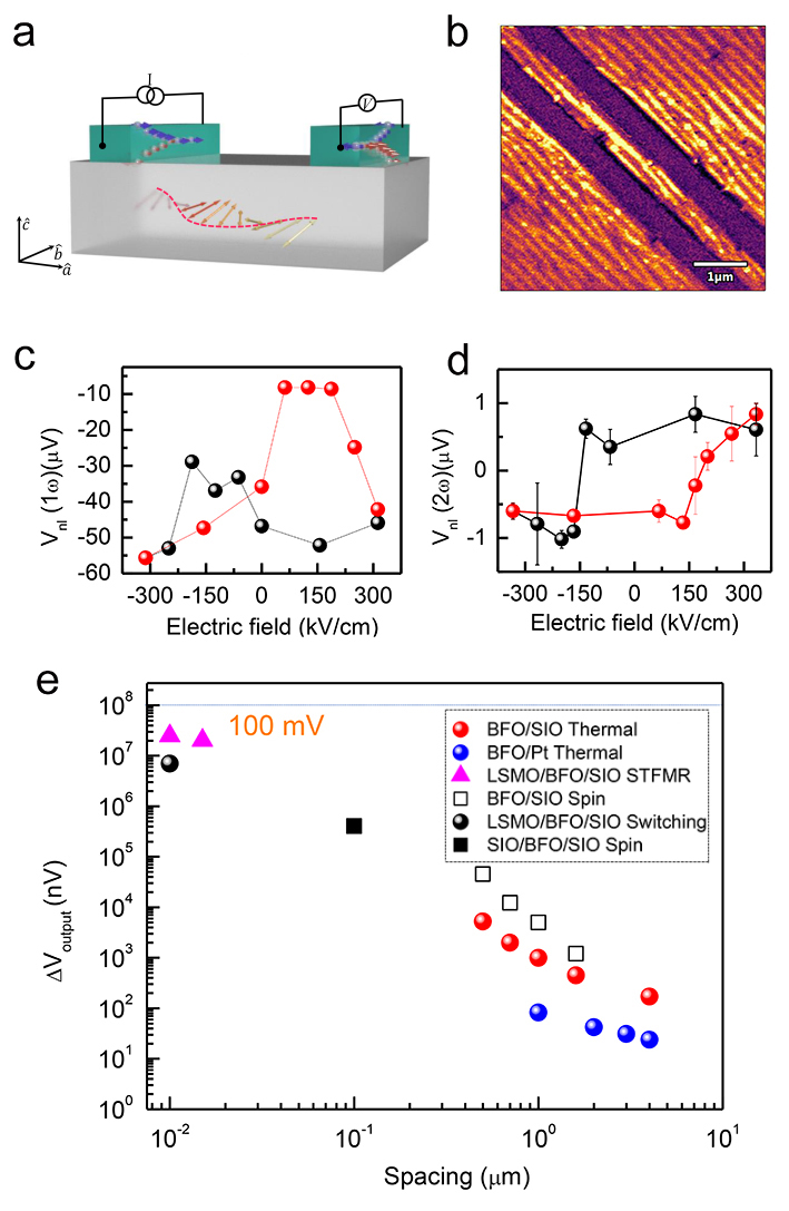
We further investigated the experimental demonstration of MESO via electrically controllable spin transport using a lateral nonlocal measurement. A schematic of the nonlocal measurement is provided (Fig. 4a); it consists of spin-orbit input and output via parallel source and detector wires, as well as magnetoelectric control. Fig. 4b illustrates well-ordered ferroelectric domains, showing the high quality of the BiFeO3 films. A nonlocal, quasi-static measurement was performed (Fig. 4c), varying the magnitude of the electric-field pulse applied in-plane across the channel from negative to positive and back again, and after each pulse measuring (over seconds) non-local voltage signals due to magnon transport between the source and detector wires (Methods). We observe a butterfly-shaped and hysteretic response in the magnon current launched by the spin Hall effect (first-harmonic voltage, Fig. 4c) and the magnon current launched thermally by the local spin Seebeck effect, respectively (second-harmonic voltage, Fig. 4d), in which the coercive fields match each other. Besides, the electric field modulations of the output voltage can be obtained with dc methods, which can minimize the inductive and capacitive effect ( Extended Data Fig. 10,11). Figure 4e presents measurements of the magnitude of these spin-transport signals as a function of changing the spacing between the source and detector wires from 500 nm to 4 m. The open squares reflect the magnitude of the signals associated with spin currents launched by the spin Hall effect (first harmonic voltage) and the red circles reflect signals launched thermally by the spin Seebeck effect (second harmonic voltage). Remarkably, the output voltage detected in BiFeO3/SrIrO3 stacks ( V) is approximately one order of magnitude larger than the counterparts in BiFeO3/Pt ( V) [51] , which is supported by the large spin-torque efficiency of SrIrO3 previously observed with the ST-FMR measurement [40, 52] and the controlled nonlocal measurements of NiFe2O4/Pt and NiFe2O4/SrIrO3 (Extended Data Fig. 13,14). The distance dependence for both types of signals in BiFeO3 fits well to the expectation for diffusive magnon propagation [53]
| (3) |
with effective diffusion lengths m (first harmonic) and m (second harmonic).
Using this result and the spin-torque efficiencies obtained above (Extended Data Fig. 5), we can calculate the inverse-spin-Hall output voltage that would be obtained for a vertical geometry with BiFeO3 thicknesses of and nm using [54]
| (4) |
where we use the values = is the spin-torque efficiency, nm
[55]
is the spin-diffusion length of SrIrO3, nm is the thickness, is the conductivity, nm is the wire length. The output voltage is on the order of mV, which is approaching the MESO target voltage of mV. A prototypical magnon-mediated MESO logic device and its circuit modeling utilizing this ferroelectrically controlled magnon propagation are shown in Extended Data Fig. 5. This observation sheds light on implementing multiferroics as the potential spin carriers and opens new possibilities of energy-efficient magnonic spin-logic devices.
References
References
- [1] Kruglyak, V. V., Demokritov, S. O. & Grundler, D. Magnonics. J. Phys. D: Appl. Phys. 43, 264001 (2010).
- [2] Lenk, B., Ulrichs, H., Garbs, F. & Münzenberg, M. The building blocks of magnonics. Phys. Rep. 507, 107–136 (2011).
- [3] Khitun, A., Bao, M. & Wang, K. L. Magnonic logic circuits. J. Phys D: Appl. Phys. 43, 264005 (2010).
- [4] Kajiwara, Y. et al. Transmission of electrical signals by spin-wave interconversion in a magnetic insulator. Nature 464, 262–266 (2010).
- [5] Chumak, A. V., Vasyuchka, V. I., Serga, A. A. & Hillebrands, B. Magnon spintronics. Nature Phys. 11, 453–461 (2015).
- [6] Bloch, F. Zur theorie des ferromagnetismus. Zeitschrift für Physik 61, 206–219 (1930).
- [7] Han, J., Zhang, P., Hou, J. T., Siddiqui, S. A. & Liu, L. Mutual control of coherent spin waves and magnetic domain walls in a magnonic device. Science 366, 1121–1125 (2019).
- [8] Hamadeh, A. et al. Full control of the spin-wave damping in a magnetic insulator using spin-orbit torque. Phys. Rev. Lett. 113, 197203 (2014).
- [9] Zhou, Y. et al. Piezoelectric strain-controlled magnon spin current transport in an antiferromagnet. Nano Lett. (2022).
- [10] Demokritov, S. O. et al. Tunneling of dipolar spin waves through a region of inhomogeneous magnetic field. Phys. Rev. Lett. 93, 047201 (2004).
- [11] Wang, H., Du, C., Hammel, P. C. & Yang, F. Antiferromagnonic spin transport from Y3Fe5O12 into NiO. Phys. Rev. Lett. 113, 097202 (2014).
- [12] Chen, X. Z. et al. Antidamping-torque-induced switching in biaxial antiferromagnetic insulators. Phys. Rev. Lett. 120, 207204 (2018).
- [13] Wang, J. et al. Epitaxial BiFeO3 multiferroic thin film heterostructures. Science 299, 1719–1722 (2003).
- [14] Wang, Y. et al. Magnetization switching by magnon-mediated spin torque through an antiferromagnetic insulator. Science 366, 1125–1128 (2019).
- [15] Lebrun, R. et al. Tunable long-distance spin transport in a crystalline antiferromagnetic iron oxide. Nature 561, 222–225 (2018).
- [16] Wang, H. et al. Spin-orbit-torque switching mediated by an antiferromagnetic insulator. Phys. Rev. Appl. 11, 044070 (2019).
- [17] Chen, X. et al. Electric field control of Néel spin–orbit torque in an antiferromagnet. Nature Mater. 18, 931–935 (2019).
- [18] Han, J. et al. Birefringence-like spin transport via linearly polarized antiferromagnetic magnons. Nature Nanotechnol. 15, 563–568 (2020).
- [19] Dkabrowski, M. et al. Coherent transfer of spin angular momentum by evanescent spin waves within antiferromagnetic nio. Phys. Rev. Lett. 124, 217201 (2020).
- [20] Chen, X. et al. Observation of the antiferromagnetic spin Hall effect. Nature Mater. 20, 800–804 (2021).
- [21] Zhang, P. et al. Control of néel vector with spin-orbit torques in an antiferromagnetic insulator with tilted easy plane. Phys. Rev. Lett. 129, 017203 (2022).
- [22] Moon, J.-H. et al. Spin-wave propagation in the presence of interfacial Dzyaloshinskii-Moriya interaction. Phys. Rev. B 88, 184404 (2013).
- [23] Iguchi, Y., Uemura, S., Ueno, K. & Onose, Y. Nonreciprocal magnon propagation in a noncentrosymmetric ferromagnet LiFe5O8. Phys. Rev. B 92, 184419 (2015).
- [24] Gitgeatpong, G. et al. Nonreciprocal magnons and symmetry-breaking in the noncentrosymmetric antiferromagnet. Phys. Rev. Lett. 119, 047201 (2017).
- [25] Kimura, T. et al. Magnetic control of ferroelectric polarization. Nature 426, 55–58 (2003).
- [26] Chu, Y.-H. et al. Electric-field control of local ferromagnetism using a magnetoelectric multiferroic. Nature Mater. 7, 478 (2008).
- [27] Zhao, T. et al. Electrical control of antiferromagnetic domains in multiferroic BiFeO3 films at room temperature. Nature Mater. 5, 823 (2006).
- [28] Rovillain, P. et al. Electric-field control of spin waves at room temperature in multiferroic BiFeO3. Nature Mater. 9, 975–979 (2010).
- [29] Gross, I. et al. Real-space imaging of non-collinear antiferromagnetic order with a single-spin magnetometer. Nature 549, 252–256 (2017).
- [30] Sando, D. et al. Crafting the magnonic and spintronic response of BiFeO3 films by epitaxial strain. Nature Mater. 12, 641–646 (2013).
- [31] Fischer, P., Polomska, M., Sosnowska, I. & Szymanski, M. Temperature dependence of the crystal and magnetic structure of BiFeO3. J. Phys. C: Solid St. Phys. 19, 1931 (1980).
- [32] Haykal, A. et al. Antiferromagnetic textures in BiFeO3 controlled by strain and electric field. Nature Communs. 11, 1–7 (2020).
- [33] Ederer, C. & Spaldin, N. A. Weak ferromagnetism and magnetoelectric coupling in bismuth ferrite. Phys. Rev. B 71, 060401(R) (2005).
- [34] Neaton, J. B., Ederer, C., Waghmare, U. V., Spaldin, N. A. & Rabe, K. M. First-principles study of spontaneous polarization in multiferroic BiFeO3. Phys. Rev. B 71, 014113 (2005).
- [35] Heron, J. et al. Deterministic switching of ferromagnetism at room temperature using an electric field. Nature 516, 370–373 (2014).
- [36] Rahmedov, D., Wang, D., Íñiguez, J. & Bellaiche, L. Magnetic cycloid of BiFeO3 from atomistic simulations. Phys. Rev. Lett. 109, 037207 (2012).
- [37] Ramazanoglu, M. et al. Local weak ferromagnetism in single-crystalline ferroelectric BiFeO3. Phys. Rev. Lett. 107, 207206 (2011).
- [38] Yang, S. et al. Above-bandgap voltages from ferroelectric photovoltaic devices. Nature Nanotechnol. 5, 143–147 (2010).
- [39] Wang, H. et al. Chiral spin-wave velocities induced by all-garnet interfacial Dzyaloshinskii-Moriya interaction in ultrathin yttrium iron garnet films. Phys. Rev. Lett. 124, 027203 (2020).
- [40] Huang, X. et al. Novel spin–orbit torque generation at room temperature in an all-oxide epitaxial La0.7Sr0.3MnO3/SrIrO3 system. Adv. Mater. 33, 2008269 (2021).
- [41] Huang, Y.-L. et al. Manipulating magnetoelectric energy landscape in multiferroics. Nature Commun. 11, 2836 (2020).
- [42] Manipatruni, S. et al. Scalable energy-efficient magnetoelectric spin–orbit logic. Nature 565, 35–42 (2019).
- [43] Noël, P. et al. Non-volatile electric control of spin–charge conversion in a SrTiO3 Rashba system. Nature 580, 483–486 (2020).
- [44] Varotto, S. et al. Room-temperature ferroelectric switching of spin-to-charge conversion in germanium telluride. Nature Electron. 4, 740–747 (2021).
- [45] Lesne, E. et al. Highly efficient and tunable spin-to-charge conversion through Rashba coupling at oxide interfaces. Nature Mater. 15, 1261–1266 (2016).
- [46] Vaz, D. C. et al. Mapping spin–charge conversion to the band structure in a topological oxide two-dimensional electron gas. Nature Mater. 18, 1187–1193 (2019).
- [47] Liu, L. et al. Spin-torque switching with the giant spin Hall effect of tantalum. Science 336, 555–558 (2012).
- [48] Merbouche, H. et al. Voltage-controlled reconfigurable magnonic crystal at the sub-micrometer scale. ACS Nano 15, 9775–9781 (2021).
- [49] Yi, D. et al. Tailoring magnetoelectric coupling in BiFeO3/La0.7Sr0.3MnO3 heterostructure through the interface engineering. Adv. Mater. 31, 1806335 (2019).
- [50] Yu, P. et al. Interface control of bulk ferroelectric polarization. PNAS 109, 9710–9715 (2012).
- [51] Parsonnet, E. et al. Non-volatile electric field control of thermal magnons in the absence of an applied magnetic field. Phys. Rev. Lett. 129, 087601 (2022).
- [52] Wang, H. et al. Large spin-orbit torque observed in epitaxial SrIrO3 thin films. Appl. Phys. Lett. 114, 232406 (2019).
- [53] Cornelissen, L. J., Liu, J., Duine, R. A., Youssef, J. B. & Van Wees, B. J. Long-distance transport of magnon spin information in a magnetic insulator at room temperature. Nature Phys. 11, 1022–1026 (2015).
- [54] Shikoh, E. et al. Spin-pump-induced spin transport in p-type Si at room temperature. Phys. Rev. Lett. 110, 127201 (2013).
- [55] Nan, T. et al. Anisotropic spin-orbit torque generation in epitaxial SrIrO3 by symmetry design. PNAS 116, 16186–16191 (2019).
- [56] Cheng, R., Xiao, J., Niu, Q. & Brataas, A. Spin pumping and spin-transfer torques in antiferromagnets. Phys. Rev. Lett. 113 (2014).
- [57] Mangeri, J. et al. Topological phase transformations in ferroelectric nanoparticles. Nanoscale 9, 1616–1624 (2017).
- [58] Permann, C. J. et al. Moose: Enabling massively parallel multiphysics simulation. SoftwareX 11, 100430 (2020).
- [59] Liu, L., Moriyama, T., Ralph, D. C. & Buhrman, R. A. Spin-torque ferromagnetic resonance induced by the spin Hall effect. Phys. Rev. Lett. 106, 036601 (2011).
- [60] Pai, C.-F., Ou, Y., Vilela-Leao, L. H., Ralph, D. C. & Buhrman, R. A. Dependence of the efficiency of spin Hall torque on the transparency of Pt/ferromagnetic layer interfaces. Phys. Rev. B 92, 064426 (2015).
- [61] Wang, Y. et al. Topological surface states originated spin-orbit torques in Bi2 Se3. Phys. Rev. Lett. 114, 257202 (2015).
- [62] Rijnders, G., Blank, D. H., Choi, J. & Eom, C.-B. Enhanced surface diffusion through termination conversion during epitaxial SrRuO3 growth. Appl. Phys. Lett. 84, 505–507 (2004).
Methods
Sample and device fabrication
The tri-layers used in this study were grown by RHEED assisted pulsed laser deposition using a KrF laser with a wavelength of 248 nm. A 20 nm La0.7Sr0.3MnO3 (5 nm SrRuO3)layer was first grown at a substrate temperature 700∘C and oxygen partial pressure 150 mTorr (100 mTorr), then a BiFeO3 layer followed with various thicknesses at a substrate temperature 700∘C and oxygen partial pressure 100 mTorr, and finally a 10 nm SrIrO3 layer finished the growth at a substrate temperature 700∘C and oxygen partial pressure 50 mTorr. The films were grown at a repetition of 2 (5 Hz) Hz, 10 Hz and 5 Hz with a laser fluence of 1.5 J/cm2, 1.5 J/cm2 and 1.2 J/cm2, respectively. After the growth, the sample was cooled to room temperature in an oxygen environment of 750 Torr at a cooling rate of 10∘C/min.
To make ST-FMR devices, the samples were first spin coated with photoresist (MiR 701), then devices with a m2 rectangular dimensions ( m2 for the electric-field-controlled experiment) were made by photolithography (Heidelberg MLA 150) followed by ion milling (Pi scientific) that stopped at the La0.7Sr0.3MnO3 layer. The remaining La0.7Sr0.3MnO3 layer was used as the bottom electrode in the switching experiments; for the ST-FMR measurements this was patterned using a H3PO4 wet etch (H3PO4 : H2O = 1 : 3). Finally, electrical contacts were made from 100 nm of Pt with a ground-signal-ground (GSG) geometry , so that when a GSG high-frequency probe made into contact with the samples the current traveling through the Pt contacts did not produce a net Oersted field at the sample.
Antiferromagnetic spin wave calculations
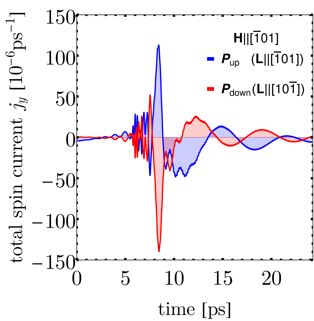
To perform the spin wave calculations, we first prepare a polar ground state corresponding to and (along with an order parameter for the octahedral antiphase tilts). We then evolve the LLG-LLB equation to find the magnetic ground state corresponding to with and .
To study the spin waves, the homogeneous magnetic ground state is perturbed with an applied field with Gilbert damping , and the spin waves are set to propagate along .
The detectable spin current in the AFM insulating layer[56] are proportional to where , ,
, and
.
More details of our simulations are provided in the SM.
Calculations are performed using the Ferret module [57] which is part of the open-source MOOSE framework [58].
ST-FMR analysis
The ST-FMR signal, , is produced across the La0.7Sr0.3MnO3/BiFeO3/SrIrO3 ST-FMR device as rectification of anisotropic magnetoresistance that oscillates at the same frequency as the input microwave current
[59]
. A microwave current at frequencies 4-6 GHz and power 12 dBm is applied to the device, with an in-plane external magnetic field oriented 45∘ with respect to the current direction. Finally,
[59]
, where is the angle dependent magnetoresistance at , is the gyromagnetic ratio, is the linewidth of the ST-FMR signal, is the field gradient of the resonance frequency, is the damping-like torque, is the field-like torque, is the symmetric Lorentzian function and is the anti-symmetric Lorentzian function respectively, is detected by Keithley 2182A nanovoltmeter, from the fits of which the symmetric component and the anti-symmetric component , which are associated with damping-like torque () and field-like torque () respectively, can be extracted. As a result, spin orbit torque efficiency- is evaluated using , where
[60, 61]
. The SOT efficiency for the samples in this work was measured from 4 GHz to 6 GHz and the error bar in Fig. 2 is a result of SOT efficiencies across different frequencies, while the error bar in extended Fig. 5 is caused by the SOT efficiency distribution across different devices.
Parameters for non-local spin transport measurements
The length of the wire is 100 , the applied voltage is 20V, the applied current is 10 , the alternating current frequency is 7 Hz.
Data availability
The data that support the findings of this study are available from the corresponding authors on reasonable request.
Acknowledgements
We are grateful for the fruitful discussions with Prof. Albert Fert, Dr. Eric Parsonnet, Dr. Yenlin Huang. X.H., D.C.R. and R.R. acknowledge the support from the SRC-JUMP ASCENT center. R.J. acknowledges the support from the U.S. Department of Energy, under contract No. DE-SC0017671. X.C., P.S., D.V., S.S., L.W.M., Z.Y., and R.R. acknowledge partial support from the U.S. Department of Energy, Office of Science, Office of Basic Energy Sciences, Materials Sciences and Engineering Division under Contract No. DE-AC02-05-CH11231 (Codesign of Ultra-Low-Voltage Beyond CMOS Microelectronics for the development of materials for low-power microelectronics). Y.L. and R.C. acknowledge the support from the Air Force Office of Scientific Research under Grant No. FA9550-19-1-0307. T.W. and Z.Q.acknowledge the support from US Department of Energy, Office of Science, Office of Basic Energy Sciences, Materials Sciences and Engineering Division under Contract No. DE-AC02-05CH11231 (van der Waals heterostructures program, KCWF16). This research used resources of the Advanced Light Source, which is a DOE Office of Science User Facility under contract no. DE-AC02-05CH11231. H.P. acknowledges support from Army Research Office and Army Research Laboratory via the Collaborative for Hierarchical Agile and Responsive Materials (CHARM) under cooperative agreement W911NF-19-2-0119. J.M. has received funding from the European Union’s Horizon 2020 research and innovation programme under the Marie Skłodowska-Curie grant agreement SCALES - 897614. D.R.R. acknowledges funding from the Ministerio dell’Università e della Ricerca, Decreto Ministeriale n. 1062 del 10/08/2021 (PON Ricerca e Innovazione). O.H. acknowledges support from the US Department of Energy, Office of Science, Basic Energy Sciences, Division of Materials Sciences and Engineering.
Author contributions
X.C. and R.R. supervised this study. X.H. carried out the synthesis and characterization of heterostructures. X.H. and X.C. fabricated the devices. X.H. and R.J. carried out the ST-FMR measurements. X.H. and X.C. carried out the current induced magnetization switching measurements. C.X. H.T. performed the non-local transport measurements. C.K. performed dynamic XMCD measurements at beamline 4.0.2 of the Advanced Light Source. Y.L. and R.C performed the theoretical calculations. J.M., D.R.R. O.H., and J.I. developed and performed the coupled polar-micromagnetic simulations. X.C., D.V., and Z.Y. devised the electronic model and performed the calculations. S.S. performed the microstructure and electronic structure characterizations. H.Z., T.W., L.C., C.H., I.H., H.P., J.Y., P.M., P.S., Z.Q., S.S., M.R., D.S., L.W.M., D.C.R., and A.F. gave suggestions on the experiments. All authors discussed the results and prepared the manuscript.
Competing interests
The authors declare no competing interests.
Additional information
Correspondence and requests for materials should be addressed to X.C. and R.R.
Reprints and permissions information is available at http://www.nature.com/reprints.