Measuring Acoustics with Collaborative Multiple Agents111The full paper with appendix together with source code can be found at https://yyf17.github.io/MACMA.
Abstract
As humans, we hear sound every second of our life. The sound we hear is often affected by the acoustics of the environment surrounding us. For example, a spacious hall leads to more reverberation. Room Impulse Responses (RIR) are commonly used to characterize environment acoustics as a function of the scene geometry, materials, and source/receiver locations. Traditionally, RIRs are measured by setting up a loudspeaker and microphone in the environment for all source/receiver locations, which is time-consuming and inefficient. We propose to let two robots measure the environment’s acoustics by actively moving and emitting/receiving sweep signals. We also devise a collaborative multi-agent policy where these two robots are trained to explore the environment’s acoustics while being rewarded for wide exploration and accurate prediction. We show that the robots learn to collaborate and move to explore environment acoustics while minimizing the prediction error. To the best of our knowledge, we present the very first problem formulation and solution to the task of collaborative environment acoustics measurements with multiple agents.
1 Introduction
Sound is critical for humans to perceive and interact with the environment. Before reaching our ears, sound travels via different physical transformations in space, such as reflection, transmission and diffraction. These transformations are characterized and measured by a Room Impulse Response (RIR) function Välimäki et al. (2016). RIR is the transfer function between the sound source and the listener (microphone). Convolving the anechoic sound with RIR will get the sound with reverberation Cao et al. (2016). RIR is utilized in many applications such as sound rendering Schissler et al. (2014), sound source localization Tang et al. (2020), audio-visual matching Chen et al. (2022), and audio-visual navigation Chen et al. (2020, 2021b, 2021a); Yu et al. (2022b). For example, to achieve clear speech in a concert hall, one might call for a sound rendering that drives more acoustic reverberation while keeping auditoriums with fewer reverberation Mildenhall et al. (2022). The key is to measure RIR at different locations in the hall. However, RIR measuring is time-consuming due to the large number of samples to traverse. To illustrate, in a m2 room with a spatial resolution of 0.5m, the number of measurable points is =121. The source location (omnidirectional) can sample one of these 121 points. Assuming a listener with four orientations (0, 90, 180, 270), this listener can choose from 121 points with four directions for each chosen point. So, the number of source-listener pairs becomes =58,564. Assuming the sampling rate, duration and precision of binaural RIR is 16K, 1 second and float32 respectively, one RIR sample requires Bytes = 128KB from computer storage (memory). The entire room would take up to KB GB. Moreover, it also means that one has to move the source/listener devices 58,564 times and performs data sending/receiving for each point.
There are some attempts to solve the challenge of storage: FAST-RIR Ratnarajah et al. (2022b) relies on handcrafted features, source (emitter) and listener (receiver) locations to generate RIR while being fidelity agnostic; MESH2IR Ratnarajah et al. (2022a) uses the scene’s mesh and source/listener locations to generate RIR while ignoring the measurement cost; Neural Acoustic Field (NAF) Luo et al. (2022) tries to learn the parameters of the acoustic field, but its training time and model storage cost grow linearly with the number of environments Majumder et al. (2022). Some work Singh et al. (2021) suggests that storing the original RIR data of the sampled points is optional, and only the acoustic field parameters must be stored. However, given a limited number of action steps, it is challenging to model the acoustic field.
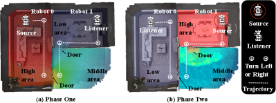
To overcome the aforementioned challenges, we propose MACMA (Measuring Acoustics with Collaborative Multiple Agents) which is illustrated in Figure 1). Both agents, one source (emitter) and one listener (receiver), learn a motion policy to perform significance sampling of RIR within any given 3D scene. The trained agents can move (according to the learned motion policy) in any new 3D scene to predict the RIR of that new scene. To achieve that, we design two policy learning modules: the RIR prediction module and the dynamic allocation module of environment reward. In Appx. B, we explore the design of environmental reward and based on this, and we further propose a reward distribution module to learn how to efficiently distribute the reward obtained at the current step, thereby incentivizing the two agents to learn to cooperate and move. To facilitate the convergence of optimization, we design loss functions separately for the policy learning module, the RIR prediction module, and the reward allocation module. Comparative experiments and ablation experiments are performed on two datasets Replica Straub et al. (2019) and Matterport3D Chang et al. (2017), verifying the effectiveness of the proposed solution. To the best of our knowledge, this work is the first RIR measurement method using two collaborative agents. The main contributions of this work are:
-
•
we propose a new setting for planning RIR measuring under finite time steps and a solution to measure the RIR with two-agent cooperation in low resource situations;
-
•
we design a novel reward function for the multi-agent decomposition to encourage coverage of environment acoustics;
-
•
we design evaluation metrics for the collaborative measurement of RIR, and we experimentally verify the effectiveness of our model.
2 Related Work
RIR generation. Measuring the RIR has been of long-standing interest to researchers Cao et al. (2016); Savioja and Svensson (2015). Traditional methods for generating RIR include statistical based methods Schissler et al. (2014); Tang et al. (2022) and physics-based methods Mehra et al. (2013); Taylor et al. (2012). However, they are computationally prohibitive. Recent methods estimate the acoustics of RIR by parameters to generate RIR indirectly Masztalski et al. (2020); Diaz-Guerra et al. (2021); Ratnarajah et al. (2021). Although these methods are flexible in extracting different acoustic cues, their predictions are independent of the source and receiver’s exact locations, making them unsuitable for scenarios where the mapping between RIR and locations of source and receiver is important (e.g. sound source localization and audiovisual navigation). FAST-RIR Ratnarajah et al. (2022b) is a GAN-based RIR generator that generates a large-scale RIR dataset capable of accurately modeling source and receiver locations, but for efficiency, they rely on handcrafted features instead of learning them, which affects generative fidelity Luo et al. (2022). Neural Acoustic Field (NAF) Luo et al. (2022) addresses the issues of efficiency and fidelity by learning an implicit representation of RIR Mildenhall et al. (2022), and by introducing global features and local embeddings. However, NAF cannot generalize to new environments, and its training time and model storage cost grows linearly with the number of environments Majumder et al. (2022). The recently proposed MESH2IR Ratnarajah et al. (2022a) is an indoor 3D scene IR generator that takes the scene’s mesh, listener positions, and source locations as input. MESH2IR Ratnarajah et al. (2022a) and FAST-RIR Ratnarajah et al. (2022b) assume that the environment and reverberation characteristics have been given, hence they only consider the fitting for the existing dataset, and ignore the measurement cost. However, our model considers how two moving agents collaborate to optimize RIR measuring from the aspects of time consumption, coverage, accuracy, etc. It is worth mentioning that our model addresses multiple scenarios, so that it is more suitable for generalizing to unseen environments.
Audio spatialization. Binaural audio generation methods comprise converting mono audio to binaural audio using visual information in video Garg et al. (2021), utilizing spherical harmonics to generate binaural audio from mono audio for training Xu et al. (2021), and generate binaural audio from video Ruohan and Kristen (2019). Using 360 videos from YouTube to generate 360-degree ambisonic sound Morgado et al. (2018) is a higher-dimensional audio spatialization. Alternatively, Rachavarapu et al. (2021) directly synthesize spatial audio. Audio spatialization has a wide range of practical applications, such as object/speaker localization Jiang et al. (2022), speech enhancement Michelsanti et al. (2021), speech recognition Shao et al. (2022), etc. Although all the above works use deep learning, our work is fundamentally different in that we propose to model binaural RIR measuring as a decision process (of two moving agents that learns to plan measurement) using time-series states as input.
Audio-visual learning. Majumder et al. (2022) harnesses the synergy of egocentric visual and echogenic responses to infer ambient acoustics to predict RIR. The advancement of audiovisual learning has good applications in many tasks, such as audiovisual matching Chen et al. (2022), audiovisual source separation Majumder and Grauman (2022) and audiovisual navigation Chen et al. (2020); Dean et al. (2020); Gan et al. (2020, 2022); Yu et al. (2022a, 2023). There are also work to use echo responses with vision to learn better spatial representations Gao et al. (2020), infer depth Christensen et al. (2020), or predict floor plans of 3D environments Purushwalkam et al. (2021). The closest work to ours is audio-visual navigation, but audio-visual navigation has navigation goals, but the agents in our setup have no clear navigation destinations.
Multi-agent learning. There are two types of collaborative multi-agents: value decomposition based methods Rashid et al. (2018, 2020) and actor-critic Foerster et al. (2018); Lowe et al. (2017) based methods. The centralized training with decentralized execution (CTDE) paradigm Wang et al. (2021) has recently attracted attention for its ability to address non-stationarity while maintaining decentralized execution. Learning a centralized critic with decentralized actors (CCDA) is an efficient approach that exploits the CTDE paradigm. Multi-agent deep deterministic policy gradient (MADDPG) and counterfactual multi-agent (COMA) are two representative examples. In our design, we have a centralized critic (named Critic) with decentralized actors (named AgentActor0 and AgentActor1). But our task differs from all the above multi-agent learning methods in that the agents in our scenario are working on a collaborative task, while previous multi-agent learning research has mainly focused on competitive tasks.
3 The Proposed Approach
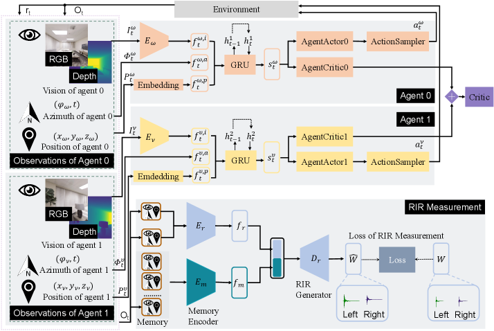
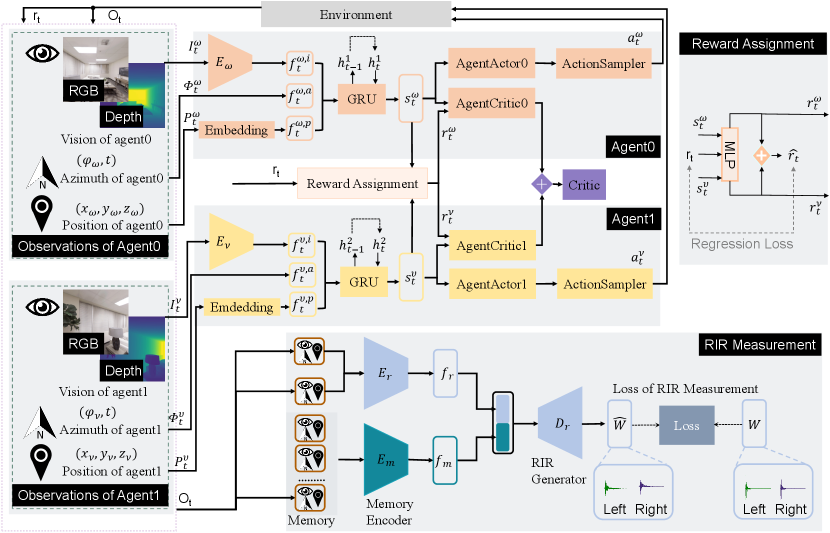
Our model MACMA has two collaborative agents moving in a 3D environment in Figure 1, using vision, position, and azimuth to measure the RIR. The proposed model mainly consists of three parts: agent 0, agent 1, and RIR measurement (see Figure 2). Given egocentric vision, azimuth, and position inputs, our model encodes these multi-modal cues to 1) determine the action for agents and evaluate the action taken by the agents for policy optimization, 2) measure the room impulse response and evaluate the regression accuracy for the RIR generator, and 3) evaluate the trade-off between the agents’ exploration and RIR measurement. The two agents repeat this process until the maximal steps have been reached.
Specifically, at each step (cf. Figure 2), the robots receive the current observation of their own and respectively,
where , ,
and are egocentric visions for robot 0 and robot 1 respectively.
and are azimuths for robot 0 and robot 1 respectively.
and are positions for robot 0 and robot 1 respectively.
or denotes the current visual input that can be RGB (1281283 pixels) and/or depth (with a dimension of 1281281) image222Both RGB and depth images capture the 90-degree field of view in front of the navigating robot.,
and are 2D vector with time.
and are 3D vector.
Although there exists a navigability graph (with nodes and edges) of the environment,
this graph is hidden from the robot, hence the robots must learn from the accumulated observations and to understand the geometry of the scene.
At each step, the robot at a certain node A can only move to another node B in the navigability graph if 1) an edge connects both nodes, and 2) the robot is facing node B.
The viable robotic action space is defined as ={MoveForward, TurnLeft, TurnRight, Stop}, where the Stop action should be executed when the robot completes the task or the number of the robot’s actions reach the maximum number of steps.
The overall goal is to predict RIR in new scene accurately and explore widely.
3.1 Problem Formulation
We denote agent 0 and agent 1 with superscript and , respectively. The game consists of state set , action sets (, ), a joint state transition function : , and the reward functions for agent 0 and for agent 1. Each player wishes to maximize their discounted sum of rewards. is the reward given by the environment at every time step in an episode. MACMA is modeled as a multi-agent Sunehag et al. (2018); Rashid et al. (2018) problem involving two collaborating players sharing the same goal:
| min. | (1) | |||
| where | ||||
where the loss is defined in Equation 5. is the expected joint rewards for agent 0 and agent 1 as a whole. and are the discounted and cumulative rewards for agent 0 and agent 1, respectively. and denote the constant cumulative rewards balance factors for agent 0 and agent 1, respectively. and are immediate reward contributions for agent 0 and agent 1, respectively. is a constant (throughout the training) reward allocation parameter. Inspired by Value Decomposition Networks (VDNs) Sunehag et al. (2018) and QMIX Rashid et al. (2018), we construct the objective function in Equation 1 by combining the non-negative partial reciprocal constraint respond to and (see theoretical details in Appx. A.1).
Agent 0, agent 1 and their optimization.
The agent 0 and agent 1 receive the current observation and at the -th step.
The visual ( and ) part is encoded into a visual feature vector using a CNN encoder: and ( for agent 0 and for agent 1).
Visual CNN encoders and are constructed in the same way (from the input to output layer): Conv8x8, Conv4x4, Conv3x3 and a 256-dim linear layer;
ReLU activations are added between any two neighboring layers.
and are embedded by an embedding layer and encoded into feature vectors and , respectively.
Then, we concatenate the two vectors together with () and () to obtain the global observation embedding and .
We transform the observation embeddings to state representations using a gated recurrent unit (GRU), .
We adopt a similar procedure to obtain .
The state vectors ( for agent 0 and for agent 1) are then fed to an actor-critic network to 1) predict the conditioned action probability distribution for agent 0 and for agent 1,
and 2) estimate the state value for agent 0 and for agent 1.
The actor and critic are implemented with a single linear layer parameterized by , , , and , respectively.
For the sake of conciseness, we use to denote the compound of , , , and hereafter.
The action samplers in Figure 2 sample the actual action (i.e. for agent 0 and for agent 1) to execute from for agent 0 and for agent 1, respectively.
Both agent 0 and agent 1 optimize their policy by maximizing the expected cumulative rewards and respectively in a discounted form.
The Critic module evaluates the actions taken by agent 0 and agent 1 to guide them to take an improved action at the next time step.
The loss of is formulated as Equation 2.
| (2) |
where and are motion loss for agent 0 and agent 1 respectively, are hyperparameters. The loss is defined as
| (3) |
where , and the estimated state value of the target network for is denoted as . . The advantage for a given length- trajectory is: , where . is entropy of . We collectively denote all the weights in Figure 2 except the above actor-critic network for agent 0 and agent 1 as hereafter for simplicity.
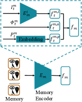
RIR measurement and its regression. We encode the observations and with encoder , and the output of the encoder is . The historical observations are sorted in the memory, and are encoded by outputting , where is the length of the memory bank. Then, and are concatenated. The predicted RIR is obtained using RIR generator . For more details for the structure of , and , please refer to Appx. A.2. RIR measurement is learned with the ground truth RIR . denote the loss of RIR measurement. are formulated as
| (4) | ||||
where is the predicted RIR from the RIR Measurement module. is the ground truth RIR. is STFT (Short-time Fourier transform) distance. It is calculated by Equation 8. 10 and 4464.2 are experimental parameters from grid search.
The total evaluation. The Critic module is implemented with a linear layer. The total loss of our model is formulated as Equation 5. We minimize following Proximal Policy Optimization (PPO) Schulman et al. (2017).
| (5) |
where is the loss component of motion for two agents, is the loss component of room impulse response prediction, and are hyperparameters. The losses and are formulated in Equation 2 and Equation 4, respectively.
The design of environmental reward.
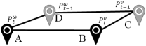
It can be seen from Figure 3 that the is formed by the positions of the two agents at the current time step and the previous time step. is the current step reward, which is calculated by the following Equation 6.
| (6) |
denotes the prediction of room impulse response. denotes coverage rate. denotes the length of the perimeter of the convex hull. denotes the area of the perimeter of the convex hull.
Among them, is the reward component in terms of measurement accuracy, which evaluates the improvement of the reward of the measurement accuracy of the current step and the reward of the measurement accuracy of the previous step. is calculated by
| (7) |
where is the measurement accuracy of the current step. As briefly explained before, is the STFT distance that can be calculated by
| (8) |
where is the magnitude spectrogram of ground truth RIR for the current time step, while is the corresponding predicted variant. is the average loss of spectral convergence for and ; and is the log STFT magnitude loss. and are computed with
| (9) |
where is Frobenius Norm. , where is real part of STFT transform333The parameters for STFT transform are FFT=1024, shift =120, window=600, window=“Hamming window”. of , is an imaginary part of the result of the STFT transform of . is defined similarly to , and the calculation process of both and are the same.
is the coverage of the current step, which is the ratio of visited nodes (only one duplicate node is counted) to all nodes in the scene at time step . We calculate by
| (10) |
and are respectively the perimeter and area of in Figure 3 at time step . We calculate and with
| (11) |
where , , and are hyperparameters (see Appx. A.9).
Overall algorithm. The entire procedure of MACMA is presented as pseudo-code in Algorithm 1.
Input: Environment , # updates , # episode , max time steps .
Parameter: Stochastic policies , initial actor-critic weights , initial other weights except for actor-critic weights .
Output:Trained weights, and .
4 Experiments
We adopt the commonly used 3D environments collected using the SoundSpaces platform Chen et al. (2020) and Habitat simulator Savva et al. (2019). They are publicly available as several datasets: Replica Straub et al. (2019), Matterport3D Chang et al. (2017) and SoundSpaces (audio) Chen et al. (2020). Replica contains 18 environments in the form of grids (with a resolution of 0.5 meters) constructed from accurate scans of apartments, offices, and hotels. Matterport3D has 85 scanned grids (1-meter resolution) of indoor environments like personal homes. To measure the RIR in Replica Straub et al. (2019) and Matterport3D Chang et al. (2017), we let two agents move a certain number of steps (250 and 300 steps for Replica and Matterport3D, respectively) throughout the scene and plan a measuring path. At every time step, the two agents measure the RIR while moving. The experimental procedure contains several phases: a) we pretrain generator under the setting ( = 1.0 and = 0.0) with random policy for both agent 0 and agent 1 in the training split, b) we train and validate every baseline with the generator fine-tune together in the training and validation split, c) we test every baseline in the test split. MACMA is benchmarked towards several baselines: Random, Nearest neighbor, Occupancy Ramakrishnan et al. (2020) and Curiosity Pathak et al. (2017). Random uniformly samples one of three actions and executes Stop when it reaches maximum steps. Nearest neighbor predict from closest experience (Appx. A.3). Occupancy orient to occupy more area, making the area of in Figure 3 larger. Curiosity strives to visit nodes that have not been visited already in the current episode. To evaluate different methods, we adopt the evaluation metrics CR (coverage rate), PE (prediction error),WCR (weighted coverage rate),RTE (RT60 Error) and SiSDR (scale-invariant signal-to-distortion ratio), among which WCR is the most important evaluation metric since it is a trade-off between encouraging high prediction accuracy and more exploration. CR is the ratio of the number of visited nodes by agents and the number of nodes in the current episode. , where is the total number of unique nodes that two agents have visited together, and is the total number of all individual nodes in the current episode. , where (Equation 8) is the ground truth RIR, is the predicted RIR. , where PES stands for Scaled Prediction Error. , where is a hyper-parameter. RTE describes the difference between the ground truth RT60 value and the predicted one. SiSDR = , where is the error vector and is the ground truth vector. We select the hyperparameters in grid search and the details are in Appx. A.4.
| Model | Replica | Matterport3D | ||||||||
|---|---|---|---|---|---|---|---|---|---|---|
| WCR () | PE () | CR () | RTE () | SiSDR () | WCR () | PE () | CR () | RTE () | SiSDR () | |
| Random | 0.3103 | 5.4925 | 0.3439 | 14.7427 | 20.3534 | 0.2036 | 5.5552 | 0.2254 | 23.5281 | 12.3042 |
| Nearest neighbor | 0.3444 | 5.4533 | 0.3817 | 14.0269 | 22.0135 | 0.2099 | 5.3342 | 0.2321 | 28.8765 | 15.2351 |
| Occupancy | 0.4464 | 3.7224 | 0.4907 | 12.5532 | 23.0666 | 0.2225 | 4.5327 | 0.2449 | 20.3399 | 18.3848 |
| Curiosity | 0.4327 | 3.4883 | 0.4742 | 10.9565 | 23.8669 | 0.2111 | 4.4255 | 0.2319 | 29.5572 | 20.0031 |
| MACMA (Ours) | 0.6977 | 3.2509 | 0.7669 | 13.8896 | 23.6501 | 0.3030 | 4.0113 | 0.3327 | 15.9338 | 21.3187 |
4.1 Experimental Results
Results are averages of 5 tests with different random seeds.
Quantitative comparison of the two datasets. Results are runs on two datasets under the experimental settings: =1.0, =1.0, =-1.0, =1.0, =2, =0.1, =-1.0. As seen from Table 1, on the Replica dataset, MACMA achieves the best results on the metrics WCR, PE and CR. But the Curiosity model has the best results on the metrics RTE and SiSDR. The Curiosity model encourages agents to visit more new nodes near them, which drive up the robots’ exploration ability (it improves performance on metrics RTE and SiSDR) while reducing their team’s performance (it reduces performance on the metric CR). The Occupancy model (ranks as the second over CR) motivates the exploratory ability of the entire group (the group of agent 0 and agent 1) but ignores their individual exploration performance (the ranks over the metrics of RTE and SiSDR lower than that of CR). MACMA combines the group exploration ability and the individual exploration ability, achieving a good trade-off between the two abilities, so that the group exploration ability of MACMA has increased by a large margin (e.g. over the CR metric) and finally won the championship on the WCR metric. On the Matterport3D dataset, MACMA achieves the best results on all metrics. As a result, we can conclude that MACMA quantitatively outperforms baselines over both datasets.
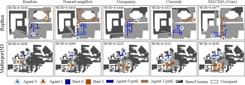
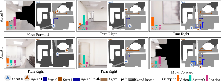
Qualitative comparison on exploration capability. Figure 4 shows the navigation trajectories of agent 0 and agent 1 for different algorithms by the end of a particular episode from the Replica (top row) and Matterport3D (bottom row) dataset. The light-gray areas in Figure 4 indicate the exploration field of the robots. We observe that MACMA tends to explore the most extensively compared to the other baselines. Particularly, there are three rooms in the entire scene in Replica, and MACMA is the only method that managed to traverse all three rooms using the same number of time steps as baselines.
Qualitative comparison on RIR prediction. We show the spectrograms generated by these models and from the ground truth in Figure 5.
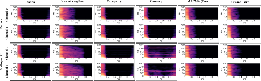
These binaural spectrograms with channel 0 and channel 1 last for one second (the x-axis is the time axis). The spectrogram of the RIR from both Random’s and Occupancy’s generation have fewer color blocks than the ground truth between 0.2 seconds and 0.4 seconds and more color blocks than the ground truth between 0.8 seconds and 1 second. The spectrogram of the RIR from the Nearest neighbor’s generation has more colored regions than the ground truth spectrogram. The spectrogram of the RIR from Curiosity’s prediction has fewer color blocks than the ground truth between 0.2 seconds and 0.4 seconds. At the same time, the spectrogram of the RIR from Curiosity’s generation has more color blocks than the ground truth between 0.8 seconds and 1 second in the Replica dataset. And the spectrogram of the RIR from Curiosity’s prediction has more colored regions than the ground truth spectrogram in the Matterport3D dataset. The spectrogram of the generated RIR from MACMA (Ours) is the closest to the ground truth spectrogram. In conclusion, from a qualitative human visual point of view, the spectral quality of the RIRs generated by our model is the best. Additionally, in Appx. A.5, we show that the RIR’s quality in the waveform of the RIRs generated by our model is also superior.
4.2 Ablation Studies
Ablation on modality. Results are run on dataset Replica under the experimental settings of =1.0, =1.0, =-1.0, =1.0, =2, =0.1, =-1.0. As shown in Table 2, RGBD (vision with RGB images and Depth input) seems to be the best choice.
More ablations. We explore the relationship between modality importance, action selection, and RIR measurement accuracy in Appx. A.6 and Appx. A.7. We present the extension model MACMARA (MACMA with a dynamic Reward Assignment module) in Appx. B.5. More ablation studies on memory size and the reward component can be found in Appx. A.4.
| Vision | WCR () | PE () | CR () | RTE () | SiSDR () |
|---|---|---|---|---|---|
| Blind | 0.5020 | 3.4966 | 0.5512 | 14.2049 | 23.0903 |
| RGB | 0.5930 | 3.8204 | 0.6541 | 15.5897 | 23.7713 |
| Depth | 0.5068 | 3.4927 | 0.5566 | 29.6905 | 23.5089 |
| RGBD | 0.6977 | 3.2509 | 0.7669 | 13.8896 | 23.6501 |
5 Conclusion
In this work, we propose a novel task where two collaborative agents learn to measure room impulse responses of an environment by moving and emitting/receiving signals in the environment within a given time budget. To tackle this task, we design a collaborative navigation and exploration policy. Our approach outperforms several other baselines on the environment’s coverage and prediction error. A known limitation is that we only explored the most basic setting, one listener (receiver), and one source (emitter), and did not study the settings with two or more listeners or sources. Another limitation of our work is that our current assessments are conducted in a virtual environment. It would be more meaningful to evaluate our method on real-world cases, such as a robot moving in a real house and learning to measure environmental acoustics collaboratively. Lastly, we have not considered semantic information about the scene in policy learning. Incorporating semantic information about the scene into policy learning would be more meaningful. The above three are left for future exploration.
Ethical Statement
This research follows IJCAI’s ethics guidelines and does not involve human subjects or privacy issues with the dataset. The dataset is publicly available.
Acknowledgments
We thank the IJCAI 2023 reviewers for their insightful feedback. This work is supported by multiple projects, including the Sino-German Collaborative Research Project Crossmodal Learning (NSFC62061136001/DFG SFB/TRR169), the National Natural Science Foundation of China (No. 61961039), the National Key R&D Program of China (No. 2022ZD0115803), the Xinjiang Natural Science Foundation (No. 2022D01C432, No. 2022D01C58, No. 2020D01C026, and No. 2015211C288), and partial funding from the THU-Bosch JCML Center.
APPENDIX
We provide additional details for MACMA and the extension version model MACMARA (Measuring Acoustics with Collaborative Multiple Agents with a reward assignment module).
A: MACMA
A.1: The theoretical point of view.
A.2: Implementation of , and in details.
A.3: Implementation of nearest neighbor in detail.
A.4: Hypter-parameter selection experiments.
A.5: More experiments for MACMA.
A.6: On modality importance for action selection.
A.6: On modality importance for action selection.
A.8: Visualization of agents’ state features.
A.9: Algorithm parameters.
B: MACMARA
B.1: The overview of MACMARA.
B.2: Reward assignment for MACMARA.
B.3: The loss of MACMARA.
B.4: Formalation of MACMARA.
B.5: Experimental results of MACMARA.
B.6: Algorithm parameters in MACMARA.
Appendix A MACMA
A.1 The Theoretical Point of View
Below we provide some theoretical points of view for formulation.
Monotonic value function factorization theory. Monotonic value function factorization for deep multi-agent reinforcement learning is proposed in QMIX Rashid et al. (2018). This theorem is cited as follows.
Lemma 1.
If then
| (12) |
where is a joint action-value function, is a history of joint action, and is a joint action.
The proof of this theorem is provided as:
Proof.
Since for , the following holds for any and the mixing network function with arguments:
|
|
(13) |
Therefore, the maximum of the mixing network function is:
. Thus,
|
|
(14) |
Letting,
|
|
(15) |
we have that
|
|
(16) |
Hence, , which proves Equation 12. ∎
The property of the decomposition theorem of the monotone value function. According to Lemma 1, we can get the following property:
Property 1.
If then Equation 1 has an optimal solution.
Construction of objective function of proposed problem. Inspired by Value Decomposition Networks (VDNs) Sunehag et al. (2018) and QMIX Rashid et al. (2018), we construct the objective function in Equation 1 by combining the non-negative partial reciprocal constraint respond to and according Property 2.
A.2 Implementations of , and in Details
Here we provide the structure of , and in details.
The structure of .
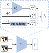
As shown in Figure 6, at the time step , the visual () part is encoded into visual feature vector using a CNN encoder.
Visual CNN encoders is constructed in this way (from the input to output layer): Conv8x8, Conv4x4, Conv3x3 and a 256-dim linear layer;
ReLU activations are added between any two neighboring layers.
is embedded by a embedding layer and encoded into feature vector .
Then, we concatenate the three vectors , and together to obtain the embedding vector .
The structure of .
As shown in Figure 7, at the time step , the visual () part is encoded into visual feature vector using a CNN encoder.
Visual CNN encoders is constructed in this way (from the input to output layer): Conv8x8, Conv4x4, Conv3x3 and a 256-dim linear layer;
ReLU activations are added between any two neighboring layers.
is embedded by a embedding layer and encoded into feature vector .
Then, we concatenate the three vectors , and together to obtain the embedding vector .
The structure of . As shown in Figure 8, the input of the is a 512d latent vector. contains several upsampling convolution blocks. A leaky rectified linear unit (LReLU), is used after each convolutional layer in with the final layer of the generator using a sigmoid activation. PN denotes pixel wise normalization, which we use in the generator. The composition of blocks is based on ProGAN Karras et al. (2018). The final step in is a reshape and extractation to make the output with a shape .
A.3 Implementation Details of Nearest Neighbor
When We finished pretrain the generator , we fixed our model and generate all the latent vector in the train and validation split for a given dataset. And we store all the latent vector in the form scene, sceneid, , listener’s azimuth, listener’s position index, source position index ( the -th latent vector in the train split). Then we fixed our pretained model and run in test split for a given dataset, the latent vector generate by Encoder and (the -th latent vector in the test split). We calculate similarity by KL (Kullback–Leibler) divergence between and , . We get the nearest neighbor by:
| (17) |
Then we get the record with the nearest neighbor scene, sceneid, , listener’s azimuth, listener’s position index, source position index. According to this record, the nearest neighbor model gets the RIR waveform by querying from the train split in a given dataset.
A.4 Hyper-Parameter Selection Experiments for MACMA
The choice of parameter . denotes the weight of MSE relative to STFT loss (See in Equation 4). Results (STDEV0.01) are averaged over 5 test runs on dataset Replica during pre-training. Table 3 shows that larger is helpful for WCR and SiSDR, but it is not good for PE and RTE, so = 1.0 is chosen after a trade-off.
| WCR () | PE () | RTE () | SiSDR () | |
|---|---|---|---|---|
| 0.0 | 0.1167 | 2.9037 | 13.6745 | -21.7048 |
| 0.5 | 0.1602 | 3.1618 | 13.6742 | -15.9758 |
| 1.0 | 0.3037 | 3.1188 | 13.8045 | 24.2508 |
The choice of parameter . is a parameter for metric WCR. Results (STDEV0.01) are averaged over 5 test runs on dataset Replica under the following experimental settings: the model is Curiosity, =1.0, =1.0, =0.0, =0.0, =2, =-1.0.
It can be seen from Table 4 that =0.1 is a good choice.
| WCR () | PE () | CR () | RTE () | SiSDR () | |
|---|---|---|---|---|---|
| 0.1 | 0.4327 | 3.4883 | 0.4742 | 10.9565 | 23.8669 |
| 0.5 | 0.2364 | 3.7721 | 0.4278 | 10.9687 | 22.9011 |
| 0.9 | 0.2653 | 3.5234 | 0.4732 | 15.9320 | 24.1206 |
The choice of parameter . is a parameter for environmental reward (See in Equation 11). Results (STDEV0.01) are averaged over 5 test runs on dataset Replica under the following experimental settings: the model is Curiosity, =1.0, =1.0, =0.0, =2, =-1.0, =0.1. It can be seen from Table 5 that =-1.0 is a good choice.
| WCR () | PE () | CR () | RTE () | SiSDR () | |
|---|---|---|---|---|---|
| 1.0 | 0.4906 | 3.4624 | 0.5384 | 12.7661 | 24.0065 |
| -1.0 | 0.5650 | 3.4742 | 0.6211 | 15.0615 | 23.7385 |
Ablation on using =1.0, =-1.0, =1.0. This is ablation study with different reward setting. We consider whether to use these reward components by using the coefficients =1.0, =-1.0, =1.0 respectively (See Equation 10). Let’s take =-1.0 as an example, if the choice is yes, then =-1.0; if the choice is no, then =0.0. Results (STDEV0.01) are averaged over 5 test runs on dataset Replica under the following experimental settings: =1.0, =2, =-1.0, =0.1. It can be seen from the Table 6 that the best model is: =1.0, =-1.0, =1.0.
| =1.0 | =-1.0 | =1.0 | WCR () | PE () | CR () | RTE () | SiSDR () |
|---|---|---|---|---|---|---|---|
| ✓ | ✗ | ✗ | 0.4327 | 3.4883 | 0.4742 | 10.9565 | 23.8669 |
| ✗ | ✓ | ✗ | 0.5215 | 3.7912 | 0.5745 | 14.6120 | 23.1906 |
| ✗ | ✗ | ✓ | 0.4464 | 3.7224 | 0.4907 | 12.5532 | 23.0666 |
| ✓ | ✓ | ✗ | 0.5650 | 3.4742 | 0.6211 | 15.0615 | 23.7385 |
| ✓ | ✗ | ✓ | 0.4663 | 3.2902 | 0.5101 | 14.7773 | 23.9743 |
| ✗ | ✓ | ✓ | 0.5468 | 3.2901 | 0.5996 | 13.8064 | 23.8852 |
| ✓ | ✓ | ✓ | 0.6977 | 3.2509 | 0.7669 | 13.8896 | 23.6501 |
The ablations about memory size . denotes the memory size for the memory encoder used in our model. Results (STDEV0.01) are averaged over 5 test runs on dataset Replica under the experimental settings: =1.0, =1.0, =-1.0, =1.0, =-1.0, =0.1. Table 7 shows that =2 is the best choice.
| WCR () | PE () | CR () | RTE () | SiSDR () | |
|---|---|---|---|---|---|
| 0 | 0.6006 | 3.1518 | 0.6582 | 15.3408 | 19.1678 |
| 2 | 0.6977 | 3.2509 | 0.7669 | 13.8896 | 23.6501 |
| 4 | 0.4930 | 3.1751 | 0.5389 | 15.0578 | 22.8031 |
| 8 | 0.5006 | 3.7761 | 0.5513 | 22.6044 | 24.9619 |
| 16 | 0.5319 | 3.1821 | 0.5822 | 14.1616 | 22.8854 |
A.5 More Experiments for MACMA
We present some results for MACMA below.
Qualitative comparison of RIR prediction in the waveform. In Figure 9, we present the RIRs generated by these models together with the ground truth.

These binaural RIRs with channels 0 and 1 last for one second (the x-axis is the time axis). The shape of the RIRs from Random’s prediction is close to ground truth, but the details need to be more accurate both in Replica and Matterport3D datasets. The RIRs from the Nearest neighbor’s prediction for channel 0 are very close to ground truth, but the ones for channel one could be better both in Replica and Matterport3D datasets. Both channels of the predicted RIR from Occupancy, Curiosity and MACMA are very close to the ground truth. Still, the tail part of the predicted RIR from Occupancy and Curiosity is worse than those of MACMA in Replica and Matterport3D datasets. All in all, from a pure visual point of view, the RIR waveforms generated by our model are of the highest quality.
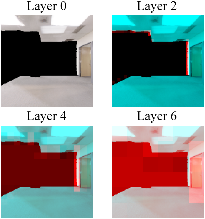
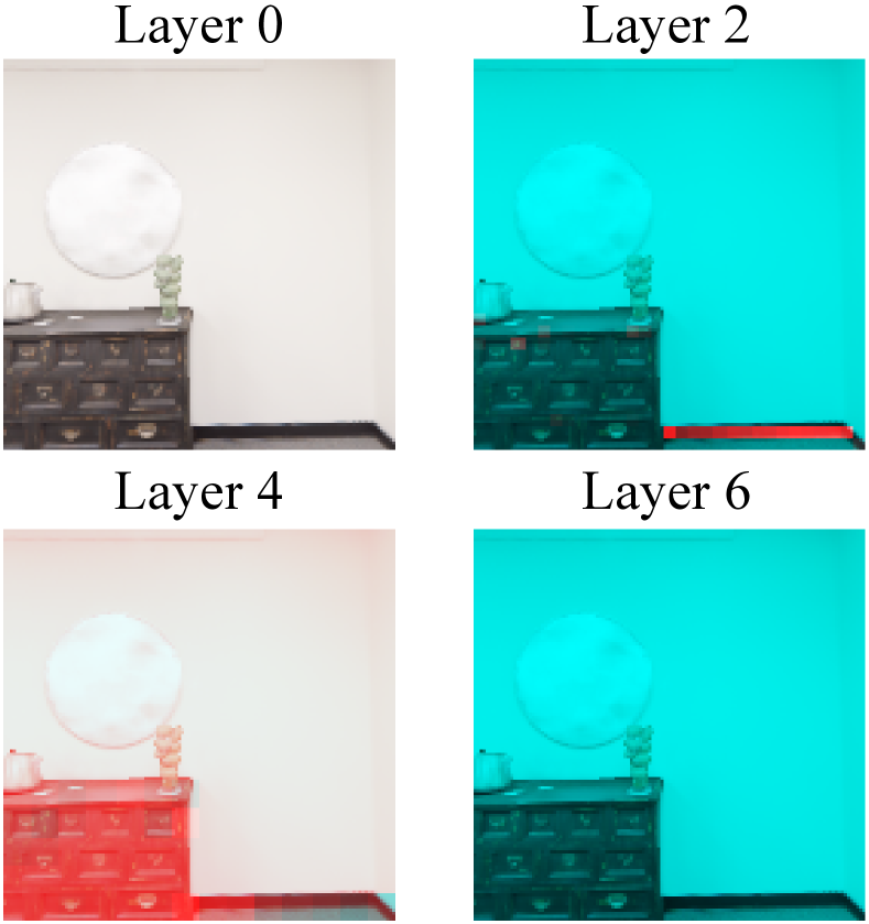
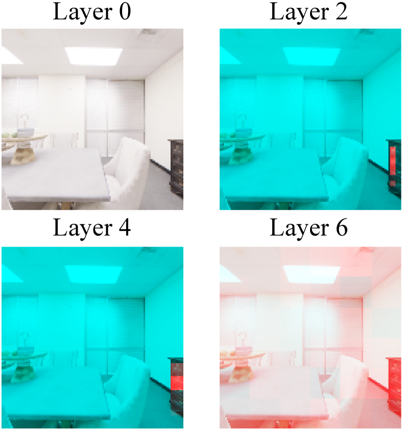
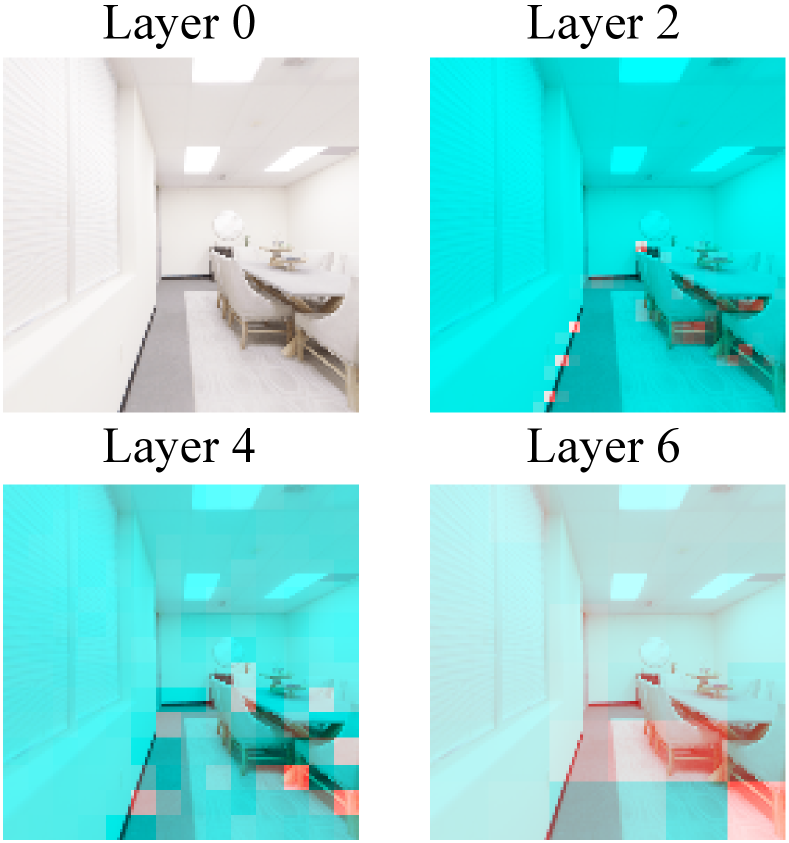
Visualization of learned features and states. In MACMA framework (cf. section 3), the encoder , , , and generate visual feature , , and , respectively. The disengagement quality of these learned features and states is important to the downstream policy learning or RIR generate. In Figure 10, we examine the semantics of visual features by overlaying the output of the visual encoder (from different layers) over the RGB images. It is easy to see that the visual encoder has learned to pay more attention to the area (in red color) where the robot can walk. This effect becomes more evident as the encoder becomes deeper.
A.6 On Dynamic Modality Importance for Action Selection
We postulate that at any given time step, the relative effects of visual (v), azimuth (a), and position (p) on agent decisions may vary. To test our hypothesis, we 1) replace one of the above three modalities (v, a, p) with random noise (such as v), 2) put the semi-corrupted input and the undamaged input in the trained model, and 3) get both the intervention action distribution and the original action distribution for a specific agent (e.g., agent 0), and 4) calculate the change, denotes the KL divergence of the original action distribution (o), and the intervened action distribution (v), which indicate the changes brought about by the intervention. Then we do the same processes for the other modal inputs (e.g., a, p) in turn to get the change in azimuth intervention and changes in position intervention . denotes the KL divergence of the original action distribution (o) and the action distribution after the azimuth random intervention (a), denotes the KL divergence of the original action distribution (o) and the intervention action distribution (p). Finally, normalize , and to get , and . , and describe visual, azimuth, and position, respectively, which indicate the influence on the agent’s decision-making (Equation 18). Intuitively, the more drastic the normalized action changes, the more dependent the agent is on that modality. Since there are two agents, the modality’s influence value needs to be calculated separately for each agent. The experimental intervention results for two agents are in Figure 11 (top for agent 0 and bottom for agent 1).
| (18) |
A.7 On Dynamic Modality Importance for the RIR Measurement
We hypothesized that the role of visual (v), azimuth (a), and position (p) in predicting the room impulse response might vary at any given time step. To test our hypothesis, 1) we replace one modality (e.g., v) of the input (v, a, p) with random noise, 2) test this intervention and non-intervention input using the trained model for 1000 episodes, and 3) record the results of both the intervention test result PE(v) and test result PE without intervention, 4) calculate the change, we use to denote the absolute change in test metric PE after visual input intervention (v). By the same steps, we can get (denote the absolute change in test metric PE after azimuth input intervention), and (indicate the total shift in test metric PE after Position input intervention).
| (19) |
Finally, normalize , , and to get , , and . , , and characterizes the impact of vision, azimuth and position on RIR prediction respectively in Equation 19. Intuitively, the larger the value of , , and , the more dependent the predicted RIR is on that modality. Since there are two agents, the modality’s influence value needs to be calculated separately for each agent. The experimental intervention results for two agents are in Figure 11 (Top for agent 0 and bottom for agent 1). Intuitively, the more significant the normalized damage degree, the greater the influence of this mode. Since there are two agents, the influence value of the modality needs to be calculated separately for each agent. We test on dataset Replica under the settings: =1.0, =1.0, =-1.0, =1.0, =0.1, =2, =-1.0. We can draw that the position input has the most significant impact on the prediction accuracy of RIR from Table 8.
| Random intervene | agent 0 () | agent 1 () | ||||||
|---|---|---|---|---|---|---|---|---|
| Vision | Azimuth | Position | ||||||
| ✓ | ✗ | ✗ | 0.14 | 0.38 | 0.19 | 0.11 | 0.33 | 0.41 |
| ✗ | ✓ | ✗ | 16.53 | 19.28 | 47.92 | 33.64 | 28.24 | 9.80 |
| ✗ | ✗ | ✓ | 83.33 | 80.34 | 51.89 | 66.25 | 71.43 | 89.79 |
A.8 Visualization of Agents’ State Features
It is more challenging to visualize the disengagement quality of the state representations and . As a result, we choose to perform dimension reduction (to two dimensions) and clustering using UMAP McInnes et al. (2018). We show the UMAP result in Figure 12 with a color coding representing the action selected by the robot.
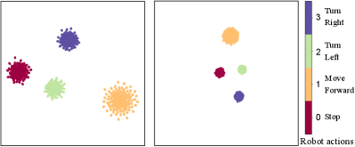
The learned state representations correlate naturally with the robot’s action selection in Figure 12.
A.9 Algorithm Parameters
The parameters used in our model are specified in Table 9.
| Parameter | Replica(Matterport3D) |
|---|---|
| number of updates | 40000(60000) |
| use linear learning rate decay | False |
| use linear clip decay | False |
| RIR sampling rate | 16000 |
| clip param | 0.1 |
| ppo epoch | 4 |
| num mini batch | 1 |
| value loss coef | 0.5 |
| entropy coef | 0.02 |
| learning rate | |
| max grad norm | 0.5 |
| num steps | 150 |
| use GAE (Generalized Advantage Estimation) | True |
| reward window size | 50 |
| window length | 600 |
| window type | “hann window” |
| number of processes | 5(10) |
| 1.0 | |
| 1.0 | |
| -1.0 | |
| 0.01 | |
| 0.99 | |
| 0.95 | |
| 1 | |
| 0.1 | |
| fft size | 1024 |
| shift size | 120 |
| hidden size | 512 |
| optimizer | Adam |
Appendix B MACMARA: MACMA with Reward Assignment
We present the extension MACMARA (Measuring Acoustics with Collaborative Multiple Agents with a dynamic Reward Assignment) here. MACMARA is the MACMA add a learnable Reward Assignment module for environmental reward.
B.1 The Overview of MACMARA
We also explored a model with with reward assignment. This model has two cooperating agents moving in a 3D environment, using vision, position and azimuth to measure the RIR. The proposed model mainly consists of four parts: agent 0, agent 1, RIR measurement and environmental reward assignment(see Figure 13). Given egocentric vision, azimuth, and position inputs, our model encodes these multi-modal cues to 1) determine the action for agents and evaluate the action taken by the agents for policy optimization, 2) measure the room impulse response and evaluate the regression accuracy for the RIR generator, and 3) evaluate the trade off between the agents’ exploration and RIR measurement, 4) environmental reward assignment. The two agents repeat this process until the maximal steps has been reached.
As 1), 2), and 3) introduced in section 3 of the main paper, we mainly introduced the environmental reward assignment module here.
B.2 Environmental Reward Assignment for MACMARA
Here we focus on a learnable reward assignment module for environmental reward in MACMARA.
Environmental reward assignment. Environmental reward assignment is implemented by a multilayer perceptron. Given , and at time step , this module output and . To enforce this learning follow a desired direction, we add and to get . Reward assignment is learned with the guide signal . The optimization objective of reward assignment is making close to . We define a regression loss to perform this optimization:
| (20) |
where and is respectively the predicted reward (for the -th time step) of the agent 0 and agent 1. is the reward obtained from the environment. is the regression loss for reward assignment module. The distribution of rewards is a combination of trainable and fixed weighting:
| (21) |
where is a constant weight parameter; and are reward weights predicted by neural networks; and are immediate reward weights. is equivalent to in Equation 20. Reward and can be respectively calculated with and .
B.3 The Loss of MACMARA
The total loss of our model are formulated as Equation 22. We minimize following Proximal Policy Optimization (PPO) Schulman et al. (2017).
| (22) |
where is the loss component of motion for two agents, is the loss component of room impulse response prediction, is the loss component of reward assignment for two agents, are hyperparameters. The loss of are formulated as Equation 2. The loss of are formulated as Equation 4. The loss of are formulated as Equation 20. .
B.4 Formulation of MACMARA
We denote the agent 0 and agent 1 with superscript and , respectively. The game consists of state set , action sets and , and a joint state transition function : . The reward function for agent 0 and for agent 1 respectively depends on the current state, next state and both the agent 0’s and the agent 1’s actions. Each player wishes to maximize their discounted sum of rewards. is the reward given by the environment at every time step in an episode. MACMARA is modeled as a multi-agent Sunehag et al. (2018); Rashid et al. (2018) problem involving two collaborating players sharing the same goal:
| (23) | ||||
| s.t. | ||||
where is defined in Equation 22. is the expected joint rewards for agent 0 and agent 1 as a whole. and are the discounted and cumulative rewards for agent 0 and agent 1, respectively. and denote the constant cumulative rewards balance factors for agent 0 and agent 1, respectively. and are immediate reward contribution for agent 0 and agent 1, respectively. and are present the trainable reward decomposition weights. is a constant (throughout the training) reward allocation parameter. The loss of are formulated as Equation 4. The loss of are formulated as Equation 20.
B.5 Experimental Results of MACMARA
In experiments below, we use two models: MACMA and the extension MACMARA (Measuring Acoustics with Collaborative Multiple Agents with a dynamic reward assignment module), to present the ablation on .
is a constant reward weight (See Equation 21). Results are run on dataset Replica under the experimental settings: =1.0, =1.0, =-1.0, =1.0, =2, =0.1. As can be seen from Table 10 =-1.0 is the best choice.
| WCR () | PE () | CR () | RTE () | SiSDR () | |
|---|---|---|---|---|---|
| -1.0♡ | 0.6977 | 3.2509 | 0.7669 | 13.8896 | 23.6501 |
| \hdashline0.0♣ | 0.6614 | 3.5727 | 0.7288 | 12.6987 | 23.1183 |
| 0.2 | 0.5287 | 3.3398 | 0.5798 | 14.0822 | 23.6715 |
| 0.4 | 0.5040 | 3.1860 | 0.5512 | 15.3278 | 23.6485 |
| 0.6 | 0.5384 | 3.3099 | 0.5904 | 12.4184 | 23.2581 |
| 0.8 | 0.4510 | 2.9755 | 0.4903 | 14.5194 | 23.8725 |
| 1.0 | 0.5471 | 3.2316 | 0.5995 | 12.9246 | 23.8201 |
: Without reward assignment module, and every agent get all the environment reward ().
: With reward assignment module, and every agent get all the environment reward ().
B.6 Algorithm Parameters in MACMARA
The parameters used in our model MACMARA are specified in Table 9 except .
References
- Cao et al. [2016] Chunxiao Cao, Zhong Ren, Carl Schissler, Dinesh Manocha, and Kun Zhou. Interactive sound propagation with bidirectional path tracing. ACM Trans. Graph., 35(6):180:1–180:11, 2016.
- Chang et al. [2017] Angel X. Chang, Angela Dai, Thomas A. Funkhouser, Maciej Halber, Matthias Nießner, et al. Matterport3d: Learning from RGB-D data in indoor environments. In International Conference on 3D Vision, pages 667–676, 2017.
- Chen et al. [2020] Changan Chen, Unnat Jain, Carl Schissler, Sebastia Vicenc Amengual Gari, Ziad Al-Halah, Vamsi Krishna Ithapu, Philip Robinson, and Kristen Grauman. Soundspaces: Audio-visual navigation in 3d environments. In ECCV, pages 17–36, 2020.
- Chen et al. [2021a] Changan Chen, Ziad Al-Halah, and Kristen Grauman. Semantic audio-visual navigation. In CVPR, pages 15516–15525, 2021.
- Chen et al. [2021b] Changan Chen, Sagnik Majumder, Ziad Al-Halah, Ruohan Gao, Santhosh Kumar Ramakrishnan, and Kristen Grauman. Learning to set waypoints for audio-visual navigation. In ICLR, 2021.
- Chen et al. [2022] Changan Chen, Ruohan Gao, Paul Calamia, and Kristen Grauman. Visual acoustic matching. In CVPR, pages 18836–18846, 2022.
- Christensen et al. [2020] Jesper Haahr Christensen, Sascha Hornauer, and Stella X. Yu. Batvision: Learning to see 3d spatial layout with two ears. In ICRA, pages 1581–1587, 2020.
- Dean et al. [2020] Victoria Dean, Shubham Tulsiani, and Abhinav Gupta. See, hear, explore: Curiosity via audio-visual association. In NeurIPS, 2020.
- Diaz-Guerra et al. [2021] David Diaz-Guerra, Antonio Miguel, and José Ramón Beltrán. gpurir: A python library for room impulse response simulation with GPU acceleration. Multim. Tools Appl., 80(4):5653–5671, 2021.
- Foerster et al. [2018] Jakob N. Foerster, Gregory Farquhar, Triantafyllos Afouras, Nantas Nardelli, and Shimon Whiteson. Counterfactual multi-agent policy gradients. In AAAI, pages 2974–2982, 2018.
- Gan et al. [2020] Chuang Gan, Yiwei Zhang, Jiajun Wu, Boqing Gong, and Joshua B. Tenenbaum. Look, listen, and act: Towards audio-visual embodied navigation. In ICRA, pages 9701–9707, 2020.
- Gan et al. [2022] Chuang Gan, Yi Gu, Siyuan Zhou, Jeremy Schwartz, Seth Alter, James Traer, Dan Gutfreund, Joshua B Tenenbaum, Josh H McDermott, and Antonio Torralba. Finding fallen objects via asynchronous audio-visual integration. In CVPR, pages 10513–10523, 2022.
- Gao et al. [2020] Ruohan Gao, Changan Chen, Ziad Al-Halah, Carl Schissler, and Kristen Grauman. Visualechoes: Spatial image representation learning through echolocation. In ECCV, pages 658–676, 2020.
- Garg et al. [2021] Rishabh Garg, Ruohan Gao, and Kristen Grauman. Geometry-aware multi-task learning for binaural audio generation from video. In BMVC, page 1, 2021.
- Jiang et al. [2022] Hao Jiang, Calvin Murdock, and Vamsi Krishna Ithapu. Egocentric deep multi-channel audio-visual active speaker localization. In CVPR, pages 10534–10542, 2022.
- Karras et al. [2018] Tero Karras, Timo Aila, Samuli Laine, and Jaakko Lehtinen. Progressive growing of gans for improved quality, stability, and variation. In 6th International Conference on Learning Representations, ICLR 2018, Vancouver, BC, Canada, April 30 - May 3, 2018, Conference Track Proceedings. OpenReview.net, 2018.
- Lowe et al. [2017] Ryan Lowe, Yi Wu, Aviv Tamar, Jean Harb, Pieter Abbeel, and Igor Mordatch. Multi-agent actor-critic for mixed cooperative-competitive environments. In NeurIPS, pages 6379–6390, 2017.
- Luo et al. [2022] Andrew Luo, Yilun Du, Michael Tarr, Josh Tenenbaum, Antonio Torralba, and Chuang Gan. Learning neural acoustic fields. CoRR, abs/2204.00628, 2022.
- Majumder and Grauman [2022] Sagnik Majumder and Kristen Grauman. Active audio-visual separation of dynamic sound sources. In ECCV, pages 551–569, 2022.
- Majumder et al. [2022] Sagnik Majumder, Changan Chen, Ziad Al-Halah, and Kristen Grauman. Few-shot audio-visual learning of environment acoustics. CoRR, abs/2206.04006, 2022.
- Masztalski et al. [2020] Piotr Masztalski, Mateusz Matuszewski, Karol Piaskowski, and Michal Romaniuk. Storir: Stochastic room impulse response generation for audio data augmentation. In Interspeech, pages 2857–2861, 2020.
- McInnes et al. [2018] Leland McInnes, John Healy, Nathaniel Saul, and Lukas Großberger. UMAP: uniform manifold approximation and projection. J. Open Source Softw., 3(29):861, 2018.
- Mehra et al. [2013] Ravish Mehra, Nikunj Raghuvanshi, Lakulish Antani, Anish Chandak, Sean Curtis, and Dinesh Manocha. Wave-based sound propagation in large open scenes using an equivalent source formulation. ACM Trans. Graph., 32(2):19:1–19:13, 2013.
- Michelsanti et al. [2021] Daniel Michelsanti, Zheng-Hua Tan, Shi-Xiong Zhang, Yong Xu, Meng Yu, Dong Yu, and Jesper Jensen. An overview of deep-learning-based audio-visual speech enhancement and separation. IEEE ACM Trans. Audio Speech Lang. Process., 29:1368–1396, 2021.
- Mildenhall et al. [2022] Ben Mildenhall, Pratul P Srinivasan, Matthew Tancik, Jonathan T Barron, Ravi Ramamoorthi, and Ren Ng. Nerf: representing scenes as neural radiance fields for view synthesis. Commun. ACM, 65(1):99–106, 2022.
- Morgado et al. [2018] Pedro Morgado, Nuno Vasconcelos, Timothy R. Langlois, and Oliver Wang. Self-supervised generation of spatial audio for 360° video. In NeurIPS, pages 360–370, 2018.
- Pathak et al. [2017] Deepak Pathak, Pulkit Agrawal, Alexei A Efros, and Trevor Darrell. Curiosity-driven exploration by self-supervised prediction. In ICML, pages 2778–2787, 2017.
- Purushwalkam et al. [2021] Senthil Purushwalkam, Sebastia Vicenc Amengual Gari, Vamsi Krishna Ithapu, Carl Schissler, Philip Robinson, Abhinav Gupta, and Kristen Grauman. Audio-visual floorplan reconstruction. In ICCV, pages 1163–1172, 2021.
- Rachavarapu et al. [2021] Kranthi Kumar Rachavarapu, Aakanksha, Vignesh Sundaresha, and A. N. Rajagopalan. Localize to binauralize: Audio spatialization from visual sound source localization. In ICCV, pages 1910–1919, 2021.
- Ramakrishnan et al. [2020] Santhosh K. Ramakrishnan, Ziad Al-Halah, and Kristen Grauman. Occupancy anticipation for efficient exploration and navigation. In ECCV, pages 400–418, 2020.
- Rashid et al. [2018] Tabish Rashid, Mikayel Samvelyan, Christian Schröder de Witt, Gregory Farquhar, Jakob N. Foerster, and Shimon Whiteson. QMIX: monotonic value function factorisation for deep multi-agent reinforcement learning. In ICML, pages 4292–4301, 2018.
- Rashid et al. [2020] Tabish Rashid, Gregory Farquhar, Bei Peng, and Shimon Whiteson. Weighted QMIX: expanding monotonic value function factorisation for deep multi-agent reinforcement learning. In NeurIPS, 2020.
- Ratnarajah et al. [2021] Anton Ratnarajah, Zhenyu Tang, and Dinesh Manocha. IR-GAN: room impulse response generator for far-field speech recognition. In Interspeech, pages 286–290, 2021.
- Ratnarajah et al. [2022a] Anton Ratnarajah, Zhenyu Tang, Rohith Aralikatti, and Dinesh Manocha. MESH2IR: neural acoustic impulse response generator for complex 3d scenes. In MM ’22: The 30th ACM International Conference on Multimedia, Lisboa, Portugal, October 10 - 14, 2022, pages 924–933. ACM, 2022.
- Ratnarajah et al. [2022b] Anton Ratnarajah, Shi-Xiong Zhang, Meng Yu, Zhenyu Tang, Dinesh Manocha, and Dong Yu. Fast-rir: Fast neural diffuse room impulse response generator. In ICASSP, pages 571–575, 2022.
- Ruohan and Kristen [2019] Gao Ruohan and Grauman Kristen. 2.5 d visual sound. In CVPR, pages 324–333, 2019.
- Savioja and Svensson [2015] Lauri Savioja and U Peter Svensson. Overview of geometrical room acoustic modeling techniques. The Journal of the Acoustical Society of America, 138(2):708–730, 2015.
- Savva et al. [2019] Manolis Savva, Jitendra Malik, Devi Parikh, Dhruv Batra, Abhishek Kadian, Oleksandr Maksymets, Yili Zhao, Erik Wijmans, Bhavana Jain, Julian Straub, Jia Liu, and Vladlen Koltun. Habitat: A platform for embodied AI research. In ICCV, pages 9338–9346, 2019.
- Schissler et al. [2014] Carl Schissler, Ravish Mehra, and Dinesh Manocha. High-order diffraction and diffuse reflections for interactive sound propagation in large environments. TOG, 33(4):1–12, 2014.
- Schulman et al. [2017] John Schulman, Filip Wolski, Prafulla Dhariwal, Alec Radford, and Oleg Klimov. Proximal policy optimization algorithms. CoRR, abs/1707.06347, 2017.
- Shao et al. [2022] Yiwen Shao, S. Z., and Dong Yu. Multi-channel multi-speaker ASR using 3d spatial feature. In ICASSP, pages 6067–6071, 2022.
- Singh et al. [2021] Nikhil Singh, Jeff Mentch, Jerry Ng, Matthew Beveridge, and Iddo Drori. Image2reverb: Cross-modal reverb impulse response synthesis. In ICCV, pages 286–295, 2021.
- Straub et al. [2019] Julian Straub, Thomas Whelan, Lingni Ma, Yufan Chen, Erik Wijmans, Simon Green, Jakob J Engel, Raul Mur-Artal, Carl Ren, Shobhit Verma, et al. The replica dataset: A digital replica of indoor spaces. CoRR, abs/1906.05797, 2019.
- Sunehag et al. [2018] Peter Sunehag, Guy Lever, Audrunas Gruslys, Wojciech Marian Czarnecki, Vinicius Zambaldi, Max Jaderberg, Marc Lanctot, Nicolas Sonnerat, Joel Z Leibo, Karl Tuyls, et al. Value-decomposition networks for cooperative multi-agent learning based on team reward. In AAMAS, pages 2085–2087, 2018.
- Tang et al. [2020] Zhenyu Tang, Lianwu Chen, Bo Wu, Dong Yu, and Dinesh Manocha. Improving reverberant speech training using diffuse acoustic simulation. In ICASSP, pages 6969–6973, 2020.
- Tang et al. [2022] Zhenyu Tang, Rohith Aralikatti, Anton Jeran Ratnarajah, and Dinesh Manocha. GWA: A large high-quality acoustic dataset for audio processing. In SIGGRAPH, pages 36:1–36:9, 2022.
- Taylor et al. [2012] Micah Taylor, Anish Chandak, Qi Mo, Christian Lauterbach, Carl Schissler, and Dinesh Manocha. Guided multiview ray tracing for fast auralization. IEEE Trans. Vis. Comput. Graph., 18(11):1797–1810, 2012.
- Välimäki et al. [2016] Vesa Välimäki, Julian Parker, Lauri Savioja, Julius O Smith, and Jonathan Abel. More than 50 years of artificial reverberation. In Audio engineering society conference, 2016.
- Wang et al. [2021] Yihan Wang, Beining Han, Tonghan Wang, Heng Dong, and Chongjie Zhang. DOP: off-policy multi-agent decomposed policy gradients. In ICLR, 2021.
- Xu et al. [2021] Xudong Xu, Hang Zhou, Ziwei Liu, Bo Dai, Xiaogang Wang, and Dahua Lin. Visually informed binaural audio generation without binaural audios. In CVPR, pages 15485–15494, 2021.
- Yu et al. [2022a] Yinfeng Yu, Lele Cao, Fuchun Sun, Xiaohong Liu, and Liejun Wang. Pay self-attention to audio-visual navigation. In BMVC, 2022.
- Yu et al. [2022b] Yinfeng Yu, Wenbing Huang, Fuchun Sun, Changan Chen, Yikai Wang, and Xiaohong Liu. Sound adversarial audio-visual navigation. In ICLR, 2022.
- Yu et al. [2023] Yinfeng Yu, Lele Cao, Fuchun Sun, Chao Yang, Huicheng Lai, and Wenbing Huang. Echo-enhanced embodied visual navigation. Neural Computation, 35(5):958–976, 2023.