Mechanical Response of Mesoporous Amorphous NiTi Alloy to External Deformations
Abstract
The porous titanium nickelide is very popular in various industries due to unique combination of physical and mechanical properties such as shape memory effect, high corrosion resistance, and biocompatibility. The non-equilibrium molecular dynamics simulation was applied to study the influence of porosity degree on mechanical properties of porous amorphous titanium nickelide at uniaxial tension, uniaxial compression, and uniform shear. We have found that the porous amorphous alloy is characterized by a relatively large value of Young’s modulus in comparison to its crystalline analogue. It has been found that the system with a percolated network of pores exhibits improved elastic characteristics associated with resistance to tensile and shear. The system contained isolated spherical pores is more resistant to compression and less resistant to tensile and shear. These results can be applied to develop and improve the methods for making amorphous metal foams.
keywords:
Alloy; Compression; Tensile; Shear deformation; Elastic moduli; Stress strain1 Introduction
Amorphous metal foams based on Ni and Ti exhibit unique physical and mechanical properties, among which are low specific weight, low stiffness, high corrosion resistance and good biocompatibility [1, 2, 3, 4, 5, 6]. These properties depend primarily on size and geometry of the pores as well as on the stability of an amorphous matrix [7, 8, 9, 10]. Existing methods for production of the porous amorphous metallic alloys, such as the spark plasma sintering and three-stage synthesis method, usually make it possible to obtain the materials with the pores greater than nm [11, 12]. These methods do not guarantee the complete absence of crystalline nuclei, which can start to grow and destroy the amorphous structure of porous material. The cooling procedure of an equilibrium liquid melt with the ultrafast cooling rates (higher than K/s) and ultrafast heat dissipation can be applied to obtain a porous material with the amorphous structure and to prevent the crystal nucleation events [13, 14, 15]. In practice, these conditions are difficult to be realized for the most known metallic alloys [16, 17, 18, 19, 20].
Titanium nickelide alloy (Ni50Ti50 or NiTi) is the most famous functional material among intermetallic compounds especially due to the shape memory effect of this alloy [21, 22, 23, 24, 25, 26, 27]. Laser and spark plasma sintering are the main methods of powder metallurgy for synthesis of crystalline NiTi with micro- and macroporous structures [28, 29, 30]. The relative simplicity and accessibility of these methods make it possible to study the mechanical properties of this alloy. However, it is difficult to obtain the porous amorphous NiTi using the above methods primarily due to the high melting point of titanium nickelide, K [31, 32]. Absence of comprehensive experimental measurements and numerical simulations is the reason why the physical and mechanical properties of porous amorphous NiTi are still poorly studied [33, 34, 35, 36, 37]. Improved computational methods and models are required to reproduce the structure and properties of the porous amorphous NiTi [23, 38].
In the present work, we construct a model of porous amorphous NiTi through rapid cooling of a low-density liquid melt. The effect of uniaxial tension, uniaxial compression and uniform shear on the porous amorphous samples with different porosity is studied. We show that the mechanical characteristics of porous amorphous NiTi differ significantly from the mechanical properties of its crystalline analogue. This is confirmed by comparing our simulation results with the available experimental data.
2 Preparation of porous amorphous NiTi
The ground crystalline state of NiTi at the temperature K is characterized by the B2 type cubic lattice. The Ni and Ti atoms are located inside the simulation box with the same length of edges nm. The periodic boundary conditions are applied in all the directions. The system consists of atoms: atoms of Ni and the same number of Ti atoms. Interaction energies between the atoms are determined by the modified embedded-atom method (MEAM) potential developed by Ko et al. for NiTi [39]. As found before in Ref. [40], this potential correctly reproduces the structural and dynamic properties of NiTi.
According to the MEAM formulation [41]], the total energy of the considered many-particle system is determined as
| (1) |
Here, is the pair interaction between atoms and separated by a distance . The embedding function is defined in the form
| (2) |
The parameter is the scaling factor for the embedding function and is the sublimation energy. The effective electron density is given by
| (3) |
where is the spherically symmetric partial electron density; () are the angular contributions (see Ref. [41]). According to Ref. [41], the quantities and depend on the atomic electron density of th atom at a distance from th atom:
| (4) |
Here, and represent the weight factors and the dumping coefficients for the partial electron densities; is the equilibrium nearest-neighbor distance in an equilibrium reference structure. In the MEAM, only the first nearest-neighbor interactions are considered. Therefore, the pair potential between two atoms separated by a distance is defined in the form
| (5) |
where
| (6) |
| (7) |
Here, is the universal function for a uniform expansion or contraction in the reference structure [42]; is the number of nearest-neighbor atoms; is the background electron density for the reference structure; is the bulk modulus; is the atomic volume of solid elements; is an adjustable parameter. The values of the quantities , , , , , , and are given in Ref. [39] for pure Ni and Ti systems as well as for NiTi alloy.
Initially, the crystalline sample has been melted at the constant pressure atm by heating above the melting (liquidus) temperature K. The equilibrated liquid samples at the temperatures , , , , and K have been prepared. Note that all these temperatures do not exceed the boiling temperature K of NiTi [43].
To generate the homogeneous amorphous sample without pores, a liquid melt at the temperature K has been isobarically cooled with the rate K/s to a state with the temperature K at the pressure atm. The generated amorphous sample has the density g/cm3 that is close to the density of crystalline NiTi, g/cm3, at the same temperature [44]. Note that the glass transition temperature of titanium nickelide estimated by T. Rouxel and Y. Yokoyama is K [45].
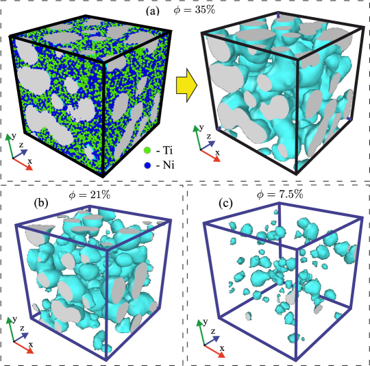
Amorphous samples with various porosity have been prepared by isochoric cooling of melt samples equilibrated at the temperatures , , , and K. Each sample has been cooled with the rate K/s to the temperature K. It should be noted that with such ultrafast cooling, a negative internal pressure arises in the melt, and the solidifying samples do not form a dense homogeneous solid phase. As a result, the melt transforms into porous amorphous solid, where the linear size of pores varies within the interval from nm to nm [Fig. 1]. After ultrafast cooling, each sample has been aged at the state with the temperature K and the pressure atm over the time ns. Amorphous samples prepared in this way have the different densities , , , and g/cm3. These values of the density are much lower than the density of the homogeneous amorphous system.
The porosity of the system is estimated by the known ratio [47]
| (8) |
In the case of the homogeneous amorphous system, we have and the coefficient of porosity is . The porosity coefficient takes the values , , , and % for porous amorphous NiTi-samples. Visualization of the porous structure given in Fig. 1 reveals predominance of the pore networks within the samples at high porosity, % [Figs. 1(a) and 1(b)]. The samples with a low degree of porosity (for example, at the porosity %) contain the isolated pores of a roughly spherical shape [Fig. 1(c)].
3 Amorphous NiTi under various types of deformation
It is well-known that the internal elastic stresses in the volume of solid arise as a result of external mechanical deformations. These stresses tend to return a deformed solid to its original shape [48]. Elastic response is defined by the stress tensor, the nine elements of which are the force components acting on an element of a unit area:
| (9) |
We evaluate the tensor components through the Irwin-Kirkwood equation [49, 50]
| (10) |
Here, the index characterizes the normal vector of a unit area, and the index corresponds to a force component, is the volume of a system, is the mass of the th atom; and are the and components of the peculiar velocity of the th atom; is the component of the force between the particles with the labels and ; is the component of the radius-vector between the particles and . The diagonal components , , in Eq. (9) are the normal stresses, which characterize the action of an external force to the unit surface of a solid in the orthogonal direction. The upper and lower symmetric triangular parts of the tensor (9) are the shear components that characterize the action of force parallel to the unit surface of solid.
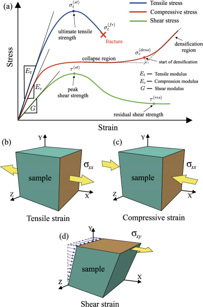
Response of considered system to various mechanical deformations is estimated by analysis of the stress-strain curves. The main elastic moduli such as the tensile modulus (or Young’s modulus) , the compression modulus and the shear modulus are determined by the slope of the linear (elastic) part of the corresponding stress-strain curve [see schematic Fig. 2(a)]. The slope of this linear part have weak dependence on the strain rate [51, 52]. Note that the high elastic moduli will correspond to materials with more pronounced elasticity.
In the given study, the amorphous NiTi samples are exposed to the following types of deformations:
-
Shear along the -direction with the constant shear rate s-1. For an elastic regime corresponding to small shear deformations [48], the shear modulus is defined as the ratio of the shear stress to the shear strain [see Figs. 2(a) and 2(d)]:
(11) where
(12) The shear stress simulations are realized via the method of non-equilibrium molecular dynamics in Lammps software package [50, 53]. In these simulations, atoms are located inside a triclinic simulation box. The shape of this simulation box changes due to the externally applied stress. For example, the simulation box changes the tilt in the -plane at shear applied along the -direction. In Lammps, the tilt of the triclinic box is usually limited by half of the length of the box side parallel to -axis. Therefore, the simulation box flips in the -plane at exceeding this limited length. These flips are cyclically repeated until the simulation completes. During each flip event, atoms are remapped into the flipped simulation box.
-
Uniaxial tension (along the -axis) with the fixed tensile rate s-1. The tensile modulus is defined as the ratio of the tensile stress to the tensile strain [see Figs. 2(a) and 2(b)]:
(13) where
(14) Here, is the length of the simulation box before the deformation, and is this length at time after the start of deformation.
Note that the strain rates of the order s-1 are achievable experimentally, for example, when a shock wave from an explosion impacts on a solid material [54, 51]. The strain with rate s-1 makes it possible to identify structural changes in the system at nanosecond time scales accessible to molecular dynamics simulations.
4 Results and Discussion
4.1 Strain by shear
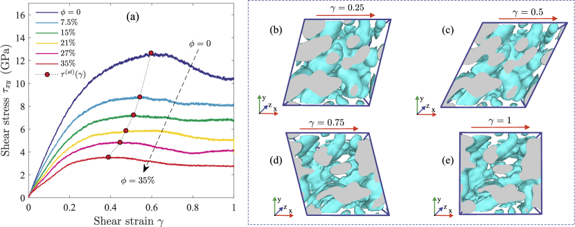
Let us consider the samples of porous amorphous NiTi with different porosity and the sample of homogeneous amorphous NiTi () under shear deformation. The shear modulus for the considered samples is evaluated from the stress-strain curves, which are depicted in Fig. 3(a). As seen in Fig. 3(a), the stress-strain curves have a similar shape. All the curves have a pronounced maximum corresponded to yield strength and a plateau that characterizes the plastic deformation regime. For the homogeneous amorphous alloy, the shear modulus, yield strength, and residual shear strength in the plastic deformation regime take the values GPa, GPa and GPa, respectively. For comparison, the found value of the shear modulus is approximately three times larger than the value GPa experimentally estimated for the austenitic crystalline phase of NiTi at identical thermodynamic conditions [55].
| , % | , GPa | , GPa | , GPa |
|---|---|---|---|
The mechanical characteristics of the amorphous system strongly depend on the porosity of samples [see the values given in Table 1]. Namely, the values of the shear modulus, yield strength, and residual shear strength exhibit decrease with the increasing porosity in the plastic deformation regime. This tendency in the values of these mechanical characteristics is quite expected since the hardness of the system becomes less with increasing porosity. We find that the shear modulus for the system with the porosity % is approximately two times larger than in the case of the system with the porosity %. The reason for this is that the less porous samples are denser. In these samples, the pores have a shape close to spherical [see Fig. 1(c)]. The spherical pores are more resistant to external deformations than pores of any other shape [36]. The samples with the high degrees of porosity, for example, with the porosity %, contain the percolating pore networks [see Fig. 1(a)]. Figs. 3(b)-(e) show that shear-induced cavities of an elongated ellipsoid shape are formed inside the porous system. At large deformations, these cavities can coalesce and form nanoscale cracks. This effect is clearly visible in the video [see the video-file “shear_strain.avi” in Supplementary Material], where the shear deformation of the porous system is visualized.
4.2 Uniaxial tensile strain
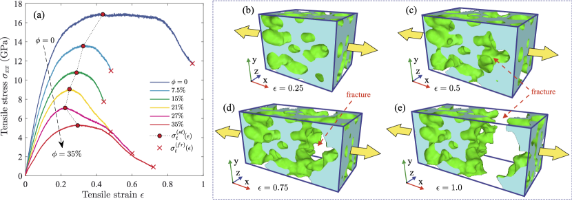
Fig. 4(a) shows the stress-strain curves obtained by uniaxial tension of porous amorphous NiTi with different porosity . The shape of these curves is typical for tensile stress. Namely, all the curves have the elastic region, the peak for ultimate tensile strength and the fracture point. The homogeneous amorphous sample exhibits the greatest elasticity and the resistance to the tensile deformation, as evidenced by the relatively large values of Young’s modulus GPa, the tensile strength GPa, and the fracture strain [see Table 2]. It is important to note that the obtained value of the tensile modulus GPa is in agreement with the experimental Young’s modulus - GPa estimated for amorphous Ni and Ti-based alloys [45, 56]. On the other hand, the crystalline NiTi of the austenitic structure has the much lower Young’s modulus - GPa at the temperature K [31].
| , % | , GPa | , GPa | , GPa | , GPa | , GPa | |||
|---|---|---|---|---|---|---|---|---|
The mechanical characteristics of the system decrease significantly with increasing porosity [see Table 2]. So, with the increasing porosity from % to %, the Young’s modulus and the tensile strength decrease by times, while the stress at the fracture point decreases by order of magnitude. These changes in the mechanical characteristics are due to decrease in the hardness of the system with increasing porosity. The complete destruction of the samples with the porosity % and % occurs at the deformations , while the samples with the porosity % are destroyed at the deformations . This is due to the fact that the pore network forms a relatively strong framework, which can stretch and, thereby, sustain large deformations without formation of nanoscale cracks. The cracks are usually formed at ultimate strain, and these cracks propagate in a direction perpendicular to the applied stress. This is clearly seen in Figs. 4(b)-(e), where fracture of the sample with the porosity % occurs through formation of single crack [see also the video-file “tensile_strain.avi” in Supplementary Material]. Our results show that the system with the isolated pores has the smallest ultimate tensile strain at the porosity %. This is mainly due to absence of a formed percolating pore network.
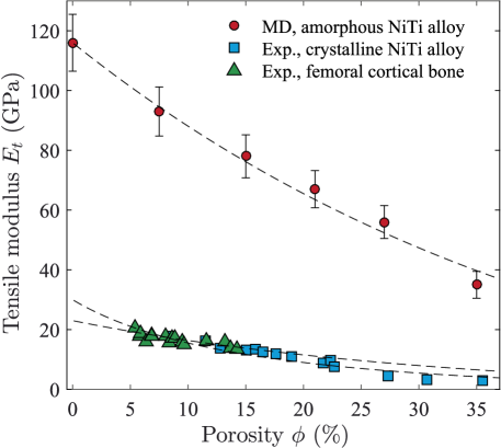
In Fig. 5, the correspondence between the tensile modulus and the porosity coefficient calculated for porous amorphous NiTi is compared with the available experimental data obtained for porous crystalline NiTi [21] and femoral cortical bone [57]. The computed values of significantly exceeds the experimental Young’s modulus in the porosity range %. This is primarily due to the presence of an amorphous solid structure, which increases the strength and hardness of the alloy. Calculated -dependence of the quantity holds the general tendency. Namely, the Young’s modulus decreases with increasing porosity according to the Nielsen’s equation [58]:
| (17) |
In Eq. (17), is the shape factor, which is usually taking as adjustable. Namely, this parameter is evaluated from fitting experimental or simulation data by Eq. (17). According to Ref. [58], the shape factor takes small values when the pores form sharply edged networks, whereas its maximal value is for the case of isolated spherical pores. We find that the computed -dependence of the Young’s modulus is well reproduced by Eq. (17) at the value [see Fig. 5]. This value corresponds to porous system with spherical pores. For comparison, the shape factor takes the value for porous NiTi obtained by the crystalline powders sintering. The presence of defects and sharp edges in crystalline powders leads to formation of pores with non-trivial geometry, which ensures a small value of the shape factor [21]. Remarkable that the value of the shape factor found for the porous amorphous NiTi is close to the value estimated for the femoral cortical bone, where the shape of pores is also close to spherical.
4.3 Uniaxial compressive strain
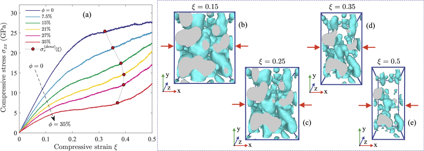
The samples of porous amorphous NiTi with various porosity were compressed to the strain . Fig. 6(a) shows the set of the stress-strain curves obtained for the samples with various porosity. Each curve has a step, that is typical for materials with a porous structure, for example, metal foams and aerogels [59, 60]. This step arises due to collapse of the pores. As a result, a material becomes more dense. The points in the stress-strain curves associated with the transition to a more dense phase are marked in Fig. 6(a). As seen in Fig. 6(a), the transition to the densification region is smooth and weakly pronounced at the porosity %. This transition becomes more pronounced at the porosity % when a percolating pore network is formed inside the system. For example, Figs. 6(b)-(e) show the system with the porosity % at different strain. As seen from these figures and from the video-file “compressive_strain.avi” in Supplementary Material, the percolating network of pores is collapsed and transformed into an ensemble of the isolated small-sized pores. As a result, the porous network is completely destroyed.
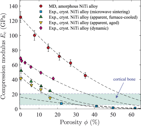
The correspondence between the uniaxial compression modulus and the porosity is presented in Fig. 7. The values of the quantity are given in Table 2. The obtained values of the modulus are compared with the experimental data for porous crystalline NiTi synthesized at room temperature by various methods [61, 62]. Note that, for the considered porosity range, the value of the quantity estimated for the porous amorphous NiTi is higher in comparison to its crystalline analogue [see Fig. 7]. The -dependence of the quantity is correctly reproduced by Bruno et al. equation [36, 64]:
| (18) |
Here, is the exponent to be determined. To evaluate the exponent , experimental data or simulation results for are approximated by Eq. (18). The exponent characterizes the geometric features of pores at compression and the exponent can take values in the range from to [36]. For example, the value corresponds to a system with spherical pores, while the value characterizes a system with pores of pronounced non-spherical geometry. As seen in Fig. 7, we obtain a good agreement between the result of Eq. (18) and the computed -dependence of at the value . For comparison, the experimental data for the crystalline analogue synthesized by powder sintering methods are well reproduced by Eq. (18) at .
It is noteworthy that the compression modulus is higher than the tensile modulus at the same porosity. According to Table 2, the difference between the values of the moduli and decreases slightly when the porosity increases from to %. Further, this difference increase with the increasing porosity from % to % mainly due to the predominance of . We assume that this non-monotonic behavior of the -dependences of and is caused by coalescence of the isolated pores and formation of the percolating network of pores at the porosity % [see Fig. 1]. Namely, the atoms form a steady framework with open-porous channels within the amorphous system. This framework creates a weak internal mechanical stress in the system that counteracts to destruction of the porous structure during compression.
5 Conclusions
In the present work, the mechanical properties of the mesoporous amorphous NiTi alloy were studied by the method of non-equilibrium molecular dynamics simulations. Samples of the system with different porosity are analysed at uniaxial tension, uniaxial compression, and uniform shear. The stress-strain curves are found, and the values of the main mechanical characteristics as functions of system porosity are calculated. It was shown that the Young’s modulus computed at tension and compression of porous amorphous NiTi exceeds the experimental values for crystalline analogues with the same porosity. This indicates that the resistance of the porous amorphous system to external deformations is higher than for the case of the porous crystalline system. The Young’s modulus tends to decrease with increasing porosity according to Nielsen’s power-law (in the case of tensile stress) and according to power-law of Bruno et al. (in the case of compressive stress). This tendency is in good agreement with the results of the available experimental data obtained for the porous crystalline NiTi and the femoral cortical bone.
We find that the degree of the system porosity is correlated with the pore geometry. The amorphous alloy with the porosity %% contains mainly isolated pores of the spherical shape. At the porosity %, the pores form a percolating network. It has been established that the amorphous solid NiTi with the isolated spherical pores better resists to compression, while it is less resistant to tensile and shear deformations. The amorphous NiTi alloy with a percolating network of pores is able to withstand large deformations at tension and shear. The results of the present work complement existing studies of the mechanical properties of Ni and Ti-based alloys with the mesoporous structure, and these results can be demanded in the development of design methods of porous amorphous alloys with the necessary characteristics of the porosity.
Acknowledgement
This study is supported by the Russian Science Foundation (project No. 19-12-00022); the computational part of the study is supported by the Russian Foundation for Basic Research (project no. 18-02-00407-a). AVM acknowledges the Foundation for the Advancement of Theoretical Physics and Mathematics “BASIS” for support.
References
- [1] Lu, G., Lu, G.Q., Xiao, Z.M., 1999. Mechanical properties of porous materials. J. Porous Mater. 6, 359–368. https://doi.org/10.1023/A:1009669730778
- [2] Zhao, C.Y., 2012. Review on thermal transport in high porosity cellular metal foams with open cells. Int. J. Heat Mass Transf. 55, 3618–3632. https://doi.org/10.1016/j.ijheatmasstransfer.2012.03.017
- [3] Qiu, Y., Yu, H., Young, M.L., 2015. Mechanical properties of NiTi-based foam with High porosity for implant applications. Shap. Mem. Superelasticity 1, 479–485. https://doi.org/10.1007/s40830-015-0040-1
- [4] Garcia-Moreno, F., 2016. Commercial applications of metal foams: Their properties and production. Materials 9, 85. https://doi.org/10.3390/ma9020085
- [5] Beltyukov, A.L., Ladyanov, V.I., Sterkhova, I.V., 2019. Effect of small nickel additions on viscosity of liquid aluminum. J. Mol. Liquids 296, 111764. https://doi.org/10.1016/j.molliq.2019.111764
- [6] Ashrafia, M.J., Arghavani, J., Naghdabadi, R., Sohrabpour, S., Auricchio, F., 2016. Theoretical and numerical modeling of dense and porous shape memory alloys accounting for coupling effects of plasticity and transformation. Int. J. Solids Struct. 88–89, 248–262. http://dx.doi.org/10.1016/j.ijsolstr.2016.03.003
- [7] Simoneau, C., Brailovski, V., Terriault, P., 2016. Design, manufacture and tensile properties of stochastic porous metallic structures. Mechanics of Materials 94, 26–37. https://doi.org/10.1016/j.mechmat.2015.11.010
- [8] Atwater, M.A., Guevara, L.N., Darling, K.A., Tschopp, M.A., 2018. Solid state porous metal production: A review of the capabilities, characteristics, and challenges. Adv. Eng. Mater. 20, 1700766. https://doi.org/10.1002/adem.201700766
- [9] Nguyen, V.T., Li, T.H., Song, S.M., Liao, Y.C., Tsai, P.H., Wong, P.C., Nguyen, V.C., Jang, J.S.C., 2019. Synthesis of biocompatible TiZr-based bulk metallic glass foams for bio-implant application. Mater. Lett. 256, 126650. https://doi.org/10.1016/j.matlet.2019.126650
- [10] Rammerstorfer, F.G., Pahr, D.H., Daxner, T., Vonach, W.K., 2006. Buckling in ThinWalled Micro and Meso Structures of Lightweight Materials and Material Compounds. Comput. Mech. 37, 470–478. https://doi.org/10.1007/s00466-005-0731-0
- [11] Schroers, J., Veazey, C., Demetriou, M.D., Johnson, W.L., 2004. Synthesis method for amorphous metallic foam. J. Appl. Phys. 96, 7723–7730. https://doi.org/10.1063/1.1818355
- [12] Schroers, J., Veazey, C., Johnson, W.L., 2003. Amorphous metallic foam. Appl. Phys. Lett. 82, 370–372. https://doi.org/10.1016/j.scriptamat.2005.10.048
- [13] Galimzyanov, B.N., Ladyanov, V.I., Mokshin, A.V., 2019. Remarkable nuances of crystallization: From ordinary crystal nucleation to rival mechanisms of crystallite coalescence. J. Cryst. Growth 526, 125214. https://doi.org/10.1016/j.jcrysgro.2019.125214
- [14] Mokshin, A.V., Khusnutdinoff, R.M., Galimzyanov, B.N., 2020. Extended short-range order determines the overall structure of liquid gallium. Phys. Chem. Chem. Phys. 22, 4122–4129. https://doi.org/10.1039/C9CP05219D
- [15] Galimzyanov, B.N., Yarullin, D.T., Mokshin, A.V., 2019. Structure and morphology of crystalline nuclei arising in a crystallizing liquid metallic film. Acta Mater. 169, 184–192. https://doi.org/10.1016/j.actamat.2019.03.009
- [16] Sanditov, D.S., Badmaev, S.S., 2019. Glass transition of liquids and frozen deformation of glass. Inorg. Mater. 55, 1046–1053. https://doi.org/10.1134/S0020168519100121
- [17] Yu, C.-J., Eifert, H.H., Banhart, J., Baumeister, J., 1998. Metal foaming by a powder metallurgy method: Production, properties and applications. Mat. Res. Innovat. 2, 181–188. https://doi.org/10.1007/s100190050082
- [18] Betts, C., 2012. Benefits of metal foams and developments in modelling techniques to assess their materials behaviour: a review. Mater. Sci. Tech. 28, 129–143. https://doi.org/10.1179/026708311X13135950699290
- [19] Tantavisut, S., Lohwongwatana, B., Khamkongkaeo, A., Tanavalee, A., Tangpornprasert, P., Ittiravivong, P., 2018. The novel toxic free titanium-based amorphous alloy for biomedical application. J. Mater. Res. Technol. 7, 248–253. https://doi.org/10.1016/j.jmrt.2017.08.007
- [20] Contuzzi, N., Campanelli, S.L., Caiazzo, F., Alfieri, V., 2019. Design and fabrication of fandom metal foam structures for laser powder bed fusion. Materials 12, 1301. https://doi.org/10.3390/ma12081301
- [21] Elahinia, M.H., Hashemi, M., Tabesh, M., Bhaduri, S.B., 2012. Manufacturing and processing of NiTi implants: A review. Prog. Mater. Sci. 57, 911–946. https://doi.org/10.1016/j.pmatsci.2011.11.001
- [22] Shelyakov, A.V., Sitnikov, N.N., Menushenkov, A.P., Korneev, A.A., Rizakhanov, R.N., Sokolova, N.A., 2013. Fabrication and characterization of amorphous–crystalline TiNiCu melt-spun ribbons. J. Alloys Comp. 577, S251–S254. https://doi.org/10.1016/j.jallcom.2012.02.146
- [23] Sepe, V., Auricchio, F., Marfia, S., Sacco, E., 2016. Homogenization techniques for the analysis of porous SMA. Comput. Mech. 57, 755–772. https://doi.org/10.1007/s00466-016-1259-1
- [24] Kalashnikov, V.S., Koledov, V.V., Kuchin, D.S., Petrov, A.V., Shavrov, V.G., 2018. A Three-point bending test machine for studying the thermomechanical properties of shape memory alloys. Instrum. Exp. Tech. 61, 306–312. https://doi.org/10.1134/S0020441218020148
- [25] Sellitto, A., Riccio, A., 2019. Overview and future advanced engineering applications for morphing surfaces by shape memory alloy materials. Materials 12, 708. https://doi.org/10.3390/ma12050708
- [26] Gardan, J., 2019. Smart materials in additive manufacturing: state of the art and trends. Virtual Phys. Prototy. 14, 1–18. https://doi.org/10.1080/17452759.2018.1518016
- [27] Tsouknidas, A., Michailidis, N., Maliaris, G., Makkar, J., Baxevanis, Th., Lagoudas, D., (2019). A numerical study of “functional fatigue” of closed-cell NiTi shape memory foams. Mechanics of Materials 131, 11–21. https://doi.org/10.1016/j.mechmat.2019.01.003
- [28] Shishkovsky, I., Yadroitsev, I., Smurov, I., 2012. Direct selective laser melting of nitinol powder. Phys. Procedia 39, 447–454. https://doi.org/10.1016/j.phpro.2012.10.060
- [29] Ye, L.L., Liu, Z.G., Raviprasad, K., Quan, M.X., Umemoto, M., Hu, Z.Q., 1998. Consolidation of MA amorphous NiTi powders by spark plasma sintering. Mater. Sci. Eng. A 241, 290–293. https://doi.org/10.1016/S0921-5093(97)00505-4
- [30] Dudina, D.V., Bokhonov, B.B., Olevsky, E.A., 2019. Fabrication of porous materials by spark plasma sintering: A Review. Materials 12, 541. https://doi.org/10.3390/ma12030541
- [31] Nitinol Devices & Components, Fremont, California. Nitinol Devices and Components, Material Data Sheet, Superelastic Nitinol Alloys: https://confluentmedical.com/wp-content/uploads/2018/09/Material-Data-Sheet-Superelastic.pdf
- [32] Anikeev, S., Hodorenko, V., Chekalkin, T., Gunther, V., Kang, Ji-hoon, Kim, Ji-soon, 2017. Fabrication and study of double sintered TiNi-based porous alloys. Smart Mater. Struct. 26, 057001. https://doi.org/10.1088/1361-665X/aa681a
- [33] Lefebvre, L.-P., Banhart, J., Dunand, D.C., 2008. Porous metals and metallic foams: Current status and recent developments. Adv. Eng. Mater. 10, 775–787. https://doi.org/10.1002/adem.200800241
- [34] Rivard, J., Brailovski, V., Dubinskiy, S., Prokoshkin, S., 2014. Fabrication, morphology and mechanical properties of Ti and metastable Ti-based alloy foams for biomedical applications. Mater. Sci. Eng. C 45, 421–433. https://doi.org/10.1016/j.msec.2014.09.033
- [35] Sawei, Q., Xinna, Z., Qingxian, H., Renjun, D., Yan, J., Yuebo, H., 2015. Research progress on simulation modeling of metal foams. Rare Metal Mat. Eng. 44, 2670–2676. https://doi.org/10.1016/S1875-5372(16)60016-4
- [36] Smolin, I.Yu., Makarov, P.V., Eremin, M.O., Matyko, K.S., 2016. Numerical simulation of mesomechanical behavior of porous brittle materials. Procedia Structural Integrity 2, 3353–3360. https://doi.org/10.1016/j.prostr.2016.06.418
- [37] Deng, S., Wang, Y., Zhuang, G., Zhong, X., Wei, Z., Yao, Z., Wang, J., 2019. Micromechanical simulation of the pore size effect on the structural stability of brittle porous materials with bicontinuous morphology. Phys. Chem. Chem. Phys. 21, 12895–12904. https://doi.org/10.1039/C9CP01582E
- [38] Panico, M., Brinson, L.C., 2008. Computational modeling of porous shape memory alloys. Int. J. Solids Struct. 45, 5613–5626. https://doi.org/10.1016/j.ijsolstr.2008.06.005
- [39] Ko, W.-S., Grabowski, B., Neugebauer, J., 2015. Development and application of a Ni-Ti interatomic potential with high predictive accuracy of the martensitic phase transition. Phys. Rev. B 92, 134107. https://doi.org/10.1103/PhysRevB.92.134107
- [40] Galimzyanov, B.N., Mokshin, A.V., 2020. Amorphous Ni50Ti50 alloy with nanoporous structure generated by ultrafast isobaric cooling. Phys. Solid State 62, 744–747.
- [41] Lee, B.-J., Baskes, M. I., 2000. Second nearest-neighbor modified embedded-atom-method potential. Phys. Rev. B 62, 8564–8567. https://doi.org/10.1103/PhysRevB.62.8564
- [42] Rose, J. H., Smith, J. R., Guinea, F., and Ferrante, J., 1984. Universal features of the equation of state of metals. Phys. Rev. B 29, 2963–2969. https://doi.org/10.1103/PhysRevB.29.2963
- [43] Nikiforov, G.A., Galimzyanov, B.N., Mokshin, A.V., 2019. Atomistic dynamics of amorphous porous nitinol. Memoirs of the Faculty of Physics 4, 1940703.
- [44] Duerig, T.W., Pelton, A.R., 1994. Materials properties handbook: Titanium alloys, ASM International. Materials Park, OH.
- [45] Rouxel, T., Yokoyama, Y., 2015. Elastic properties and atomic bonding character in metallic glasses. J. Appl. Phys. 118, 044901. https://doi.org/10.1063/1.4926882
- [46] Stukowski, A., 2014. Computational analysis methods in atomistic modeling of crystals. JOM 66, 399–407. https://doi.org/10.1007/s11837-013-0827-5
- [47] Dullien, F.A.L., 1992. Porous media. Fluid transport and pore structure. Academic Press.
- [48] Landau, L.D., Lifshitz, E.M., 1970. Theory of elasticity, Volume 7 of A Course of Theoretical Physics. Pergamon Press.
- [49] Thompson, A.P., Plimpton, S.J., Mattson, W., 2009. General formulation of pressure and stress tensor for arbitrary many-body interaction potentials under periodic boundary conditions. J. Chem. Phys. 131, 154107. https://doi.org/10.1063/1.3245303
- [50] Evans, D.J., Morriss, G.P., 2008. Statistical mechanics of non-equilibrium liquids. Cambridge University, New-York.
- [51] Shen, L.-M., 2012. Combined grain size, strain rate and loading condition effects on mechanical behavior of nanocrystalline Cu under high strain rates. Acta Mech. Sin. 28, 1125–1132. https://doi.org/10.1007/s10409-012-0140-5
- [52] Tang, C., Yi, J., Xu, W., Ferry, M., 2018. Temperature rise in shear bands in a simulated metallic glass. Phys. Rev. B 98, 224203. https://doi.org/10.1103/PhysRevB.98.224203
- [53] Galimzyanov, B.N., Mokshin, A.B., 2018. Morphology of critically sized crystalline nuclei at shear-induced crystal nucleation in amorphous solid. J. Rheol. 62, 265–275. https://doi.org/10.1122/1.5003238
- [54] Bringa, E.M., Caro, A., Wang, Y., Victoria, M., McNaney, J.M., Remington, B.A., Smith, R.F., Torralva, B.R., van Swygenhoven, H., 2005. Ultrahigh strength in nanocrystalline materials under shock loading,. Sci. 309, 1838–1841. https://doi.org/10.1126/science.1116723
- [55] Sun, Q.-P., Li, Z.-Q., 2002. Phase transformation in superelastic NiTi polycrystalline micro-tubes under tension and torsion-from localization to homogeneous deformation. Int. J. Solids Struct. 39, 3797–3809. https://doi.org/10.1016/S0020-7683(02)00182-8
- [56] Wang, W.H., 2005. Elastic moduli and behaviors of metallic glasses. J. Non-Cryst. Solids 351, 1481–1485. https://doi.org/10.1016/j.jnoncrysol.2005.03.024
- [57] Dong, X.N., Guo, X.E., 2004. The dependence of transversely isotropic elasticity of human femoral cortical bone on porosity. J. Biomech. 37, 1281–1287. https://doi.org/10.1016/j.jbiomech.2003.12.011
- [58] Nielsen, L.F., 1984. Elasticity and damping of porous materials and impregnated materials. J. Am. Ceram. Soc. 67, 93–98. https://doi.org/10.1111/j.1151-2916.1984.tb09622.x
- [59] Smith, B.H., Szyniszewski, S., Hajjar, J.F., Schafer, B.W., Arwade, S.R., 2012. Steel foam for structures: A review of applications, manufacturing and material properties. J. Constr. Steel Res. 71, 1–10. https://doi.org/10.1016/j.jcsr.2011.10.028
- [60] Ma, H., Zheng, X., Luo, X., Yi, Y., Yang, F., 2018. Simulation and analysis of mechanical properties of silica aerogels: from rationalization to prediction. Materials 11, 214. https://doi.org/10.3390/ma11020214
- [61] Xu, J.L., Bao, L.Z., Liu, A.H., Jin, X.J., Tong, Y.X., Luo, J.M., Zhong, Z.C., Zheng, Y.F., 2015. Microstructure, mechanical properties and superelasticity of biomedical porous NiTi alloy prepared by microwave sintering. Mater. Sci. Eng. C 46, 387–393. https://doi.org/10.1016/j.msec.2014.10.053
- [62] Greiner, C., Oppenheimer, S.M., Dunand, D.C., 2005. High strength, low stiffness, porous NiTi with superelastic properties. Acta Biomater. 1, 705–716. https://doi.org/10.1016/j.actbio.2005.07.005
- [63] Khan, S.N., Warkhedkar, R.M., Shyam, A.K., 2014. Human bone strength evaluation through different mechanical tests. Int. J. Curr. Eng. Technol. 2, 539–543. http://Dx.Doi.Org/10.14741/Ijcet/Spl.2.2014.102
- [64] Bruno, G., Efremov, A.M., Levandovskyi, A.N., Clausen, B., 2011. Connecting the macro- and microstrain responses in technical porous ceramics: modeling and experimental validations. J. Mater. Sci. 46, 161–173. https://doi.org/10.1007/s10853-010-4899-0