Medial Axis Isoperimetric Profiles
Abstract
Recently proposed as a stable means of evaluating geometric compactness, the isoperimetric profile of a planar domain measures the minimum perimeter needed to inscribe a shape with prescribed area varying from 0 to the area of the domain. While this profile has proven valuable for evaluating properties of geographic partitions, existing algorithms for its computation rely on aggressive approximations and are still computationally expensive. In this paper, we propose a practical means of approximating the isoperimetric profile and show that for domains satisfying a “thick neck” condition, our approximation is exact. For more general domains, we show that our bound is still exact within a conservative regime and is otherwise an upper bound. Our method is based on a traversal of the medial axis which produces efficient and robust results. We compare our technique with the state-of-the-art approximation to the isoperimetric profile on a variety of domains and show significantly tighter bounds than were previously achievable.
{CCSXML}<ccs2012> <concept> <concept_id>10010147.10010371.10010352.10010381</concept_id> <concept_desc>Computing methodologies Collision detection</concept_desc> <concept_significance>300</concept_significance> </concept> <concept> <concept_id>10010583.10010588.10010559</concept_id> <concept_desc>Hardware Sensors and actuators</concept_desc> <concept_significance>300</concept_significance> </concept> <concept> <concept_id>10010583.10010584.10010587</concept_id> <concept_desc>Hardware PCB design and layout</concept_desc> <concept_significance>100</concept_significance> </concept> </ccs2012>
\ccsdesc[300]Computing methodologies Collision detection \ccsdesc[300]Hardware Sensors and actuators \ccsdesc[100]Hardware PCB design and layout
1 Introduction
The isoperimetric problem can be traced back to Dido’s problem, in which Dido—the founder of Carthage—wished to maximize her territory while bounding it with a limited supply of strips of bull’s hide [VF83]. This problem is solved by invoking the isoperimetric inequality, which states for any shape of perimeter and area , ; as a result, her encapsulated territory is maximized by a circle.
The isoperimetric inequality motivates the definition of the isoperimetric ratio , which quantifies compactness of a shape. In the study of geography and political redistricting, the word compactness is used informally to distinguish shapes that are not too irregular or distorted, rather than in the formal mathematical sense. For example, a perfect circle is the most compact shape achievable, with isoperimetric ratio , while a shape with fractal-esque boundary will have a ratio close to . Beyond serving as a basic tool in analytic geometry, the isoperimetric ratio—known as the Polsby–Popper score in political science [PP91]—has found application in comparing geographic partitions used in political redistricting.
Applications of the isoperimetric ratio to geographic domains suffer from the “coastline paradox.” In particular, since geographic boundaries can have fractal shapes, their lengths are not well-defined and can change at different length scales. The isoperimetric ratio is unstable to boundary perturbation and will change its compactness score depending on the resolution of the input shape (see Figure 1). This instability can have a severe impact on applications to political redistricting where a low compactness score is frequently presented as evidence of improper intent in the line drawing process [BNNS19, BS20]. Additionally, when alternative plans are considered in court, scores like Polsby–Popper are used to evaluate whether a proposed plan would be a permissible remedy. While straightforward geometric measures are convenient for making direct pairwise comparisons in court, their simplicity and inherent instability means that they are exploitable and insufficient to distinguish between multiple potential types of undesirable shapes.
Recent works have introduced variations of the classical isoperimetric problem to address the shortcomings above. In particular, the isoperimetric profile (IP) modifies the original problem by producing a function rather than a single value. Intuitively, the isoperimetric profile augments the isoperimetric ratio by outputting a geometric compactness score for all length scales rather than at just one. More formally, the profile of a domain is defined via the following optimization:
| (IP) |
where is an inscribed shape within , is the perimeter of , is the area of , and is the multi-scale resolution parameter of the profile. The profile for a given value of is the smallest perimeter a shape inscribed in can have while also maintaining area . There is no restriction that must be connected. Following the notation in [LS19], we will refer to the that solves this optimization as .
While the isoperimetric ratio is a scalar measurement of compactness, the isoperimetric profile provides an entire plot that measures the multiscale compactness of a domain. As such, it is more suited to noisy data such as geographic domains that often exhibit fractal boundaries on coastlines and rocky territories. The notion of multiscale compactness is demonstrated in Figure 2 for two near-circular shapes that manifest extreme isoperimetric ratio values. While the ratio strongly distinguishes these two shapes, the profile reveals that they are in fact similar at coarse length scales and only differ at fine length scales. Furthermore, the isoperimetric profile is invariant to translation and rotation of the domain. When the areas of different domains are normalized, their isoperimetric profiles can be used as multiscale shape descriptors for measuring similarity and clustering.
Despite the theoretical advantages of the isoperimetric profile, the lack of an efficient algorithm to compute it heavily deters its usage in practice. A recent method takes a convex relaxation of Eq. (IP) using total variation (TV) on an Eulerian grid to compute the convex lower envelope of [DLSS19]. This method suffers from several drawbacks: the lower bound is not tight on all valid values of for any domain; the discretization converges poorly under mesh refinement; and computation of does not leverage results from previously computed values , although we note that this final issue could be possibly addressed by using a solution for smaller as the starting point for the next round of optimization.

The drawbacks in [DLSS19] limit its applicability to accurately obtaining the isoperimetric profile. To rectify this, we present a novel algorithm that computes upper bounds on the isoperimetric profile that are provably tight for a restricted class of domains. Outside this class, we still attain tight bounds on a subset of scales . Our algorithm exploits restrictions on the mean curvature of [GMT80] as well as recent results on values of for special domains [LS19]. This leads us to the construction of our bound via the medial axis of . We use our algorithm to bound isoperimetric profiles for a large variety of domains, including districts, states and countries at various resolutions. We show—on domains for which the isoperimetric profile is known—that our bound is much tighter than bounds computed by previous state-of-the-art.
Our main technical contributions are as follows:
-
•
We generalize previous approaches to understanding the isoperimetric profile by constructing it through the medial axis.
-
•
We design a novel algorithm for efficiently computing upper bounds to the isoperimetric profile.
-
•
We prove that our bound is tight for a restricted set of domains.
-
•
We prove that on general domains our bound is tight for a range of values derived from properties of .
-
•
We provide experiments demonstrating that our bounds on the isoperimetric profile are tight enough to be used in practice.
2 Related Work
While the original isoperimetric problem has been solved for centuries, many variants remain open and actively studied. For a summary of results on the subject in 2D, on Riemannian 3-manifolds, and on measures, see [Ros05].
A key application of the isoperimetric ratio is as a way to measure geometric compactness to detect gerrymandering [PP91]. In this context, it is known as the Polsby-Popper score. In some U.S. states, it is even a legally required statistic to be reported for any proposed districting plan [voMSRP11]. Despite this, [KKKng, DT18, BNNS19, BS20] show that this score is not a reliable measure of compactness. [DT18] suggest a discrete Polsby-Popper score on graphs that alleviates problems with map projection at the cost of geometric sensitivity. [Ehr82] suggest a variation of the isoperimetric ratio that computes the ratio of the area of the full domain to the area of its maximum inscribed circle. Ultimately, this measure ignores high resolution features of the domain. Note that the Ehrenburg test can be extracted from the front of the isoperimetric profile, while the Polsby-Popper score can be extracted from its end with interpolation in between. .
Many variations of the isoperimetric problem differ from the isoperimetric profile we consider in that they use the relative perimeter of the inscribed domain rather than full perimeter. While the relative perimeter formulations do not count shared boundary between the domain and its inscribed subdomain [Ros05], the full perimeter does. [SZ98] provide conditions under which a perimeter-minimizing subdomain of a convex set is also convex. [LS19] study the maximizers of a curvature functional with close ties to the isoperimetric profile when restricted to domains with no necks. Their results provide a method for computing the isoperimetric profile when restricted to no neck domains. [DLSS19] propose the first algorithmic approach to the isoperimetric profile on general domains by using TV as a generalized measurement of perimeter of a domain. This relaxation of the problem yields the convex lower envelope of the isoperimetric profile. It remains unknown if computation of the exact isoperimetric profile for 2D polygons is in the polynomial complexity class. Additional open problems for the 2D profile are summarized in [CFG12].
2.1 Properties of solutions to (IP)
While there is no known efficient algorithm to compute the full isoperimetric profile, much is known about . In particular, for any fixed value of , the free boundary of , must have constant and nonsingular mean curvature [GMT80]. In addition, and must meet tangentially, and any free boundary of must be a circular arc [BES49]. For a small subset of values of , and are known in closed form [LS19]. We will expand on this in §3.3 after establishing more notation and geometric tools.
3 Preliminaries
3.1 Domains
Literature on the isoperimetric profile has typically focused on suitably regular Jordan domains.
Definition 3.1 (Jordan Curve [Sul12]).
A Jordan curve or a simple closed curve in the plane is the image of an injective continuous map .
Definition 3.2 (Jordan Domain [Sul12]).
A Jordan domain is the interior of a Jordan curve.
Beyond restricting attention to Jordan domains, there is typically an additional regularity constraint that , where denotes the Lebesgue 2-dimensional measure. Domains satisfying this condition include any finite polygon and Jordan domains with smooth boundary. For contrast, Osgood curves are Jordan curves that can have nonzero area [Kno17], but for our purposes these will not be considered. The set of suitably regular Jordan domains will be denoted .
3.2 Necks
We will further refine these domains by the characteristics of their necks.
Definition 3.3 (Neck, [LNS17]).
A domain has a neck of radius if there exists a pair of balls such that there does not exist a continuous curve satisfying , , and .
Let denote the smallest value of for which has a neck. This definition is built intuitively on the idea of a bottleneck where objects of a certain size are unable to pass through. A domain that does not satisfy Definition 3.3 for any has no neck, i.e., . For example, star domains have no necks. In contrast, it is clear that the shape in Figure 3 has . This definition does not have a concept of multiple necks nor does it take into account the locations of necks. We will provide a new definition in §6.1 that generalizes necks to incorporate these concepts.
3.3 Morphological Operations


Natural variations of a shape are given by morphological operations. Furthermore for limited values of can be characterized by the morphological opening of . We will also use morphological closing in §7.2 to clean up our results. For these reasons, we provide their definitions; see [Ser00] for more discussion.
Let be a ball of radius centered at and . Given a starting domain , its erosion by is
| (1) |
Its dilation by is
| (2) |
Its opening by is
| (3) |
Finally, its closing by is
| (4) |
These operations and their results are depicted in Figure 3. Intuitively, the opening can be thought of as a blurring of the convex corners of a shape. The closing can be thought of as a way of filling in small holes or smoothing out concave corners of a shape.
With this notation, we recall a property of the isoperimetric profile, namely that when with corresponding area [LS19]. It follows that when restricted to no neck domains, the isoperimetric profile can be computed by opening [LS19, Theorem 2.3]. For domains with necks, however, the opening is not generally equal to . This is exemplified in Figure 3 where the opening has singular curvature near the neck. Furthermore, we find that in practice the range accounts for a very small portion of the isoperimetric profile on domains with necks.
3.4 Medial Axis
One of our key ideas is to connect the widely used medial axis to the isoperimetric profile. The medial axis allows us to formulate a new definition of neck that will be helpful for our analysis.
Intuitively, the medial axis of a 2D domain is a set of curves that characterize the skeleton of a shape. To formalize this idea, let be the projection of onto the closest boundary point. The medial axis of is
| (5) |
Said differently, the medial axis contains all interior points where the closest boundary point is non-unique. The medial axis of a 2D polygon can be decomposed into the union of linear and quadratic edge segments [AVP99]. Each medial axis edge segment is a set of points that are equidistant from two boundary objects, governors: two boundary vertices (vert-vert), two boundary edges (edge-edge), or one boundary vertex and one boundary edge (edge-vert). These edge segments join at medial axis nodes. The medial axis transform is the coupling of the medial axis with its radius function , which measures its distance to the boundary. The medial axis transform is unique, and it can be used to reconstruct [Blu67]. An example medial axis is provided in Figure 4. Lastly, we denote the the largest circle inscribed in by with corresponding radius and center . We assume is unique, which is guaranteed for a generic domain, but not for domains with too much symmetry. In such a case, a randomized boundary perturbation will give us the needed genericity.


4 Motivating the Algorithm
We build our algorithm by first considering ways of computing the isoperimetric profile on domains with no necks, and then extending them to general domains. As mentioned in §3.3, for domains with no necks, is always equal to for some . Since decreases strictly monotonically with , and are in correspondence. Thus, we can build the isoperimetric profile by measuring the area and perimeter of for values of . It remains to consider different algorithmic ways of building . A key consideration of our algorithm will be how well it extends to general domains with necks.
4.1 Direct computation of
The opening of a 2D domain is simple to compute from modern geometry processing tools and generates feasible solutions to problem (IP) on general domains. Unfortunately, the IP upper bound generated by measuring the perimeter of exhibits several undesirable traits on domains with necks. Firstly, varies discontinuously with , leaving large gaps in the profile; we repair this issue in §7.2. Second, this IP bound is not monotonic, and we know the true isoperimetric profile should always monotonically increase. Finally, can have singular curvature on free boundaries, while cannot. For these reasons direct computation of does not extend well to domains with necks. To fix these shortcomings, we propose a novel medial axis based approach.
4.2 Medial Axis Limited Reconstruction
Recall from §3.4 that the medial axis transform is invertible i.e. we can reconstruct from and its radius function . Unsurprisingly, performing the reconstruction on a subset of will produce a subset of . We will refer to these as limited reconstructions.
Definition 4.1 (Limited Reconstruction).
Let be a subset of the medial axis. The medial axis limited reconstruction of by is .
When , . It turns out that for a particular choice of , we can relate the morphological opening of a domain to its limited reconstruction.
Proposition 1.
For a radius parameter and ,
| (6) |
For proof, see §LABEL:proof:medaxrecon. The relationship between morphological operations and the morphological skeleton has been studied in image processing [Lan77], where a similar statement is made in the discrete setting. Recall that the isoperimetric profile of no neck domains in can be constructed by morphological opening. By Proposition 1 these can now be constructed from subsets of the medial axis. Furthermore, can be built iteratively due to the following result:
Proposition 2.
For generic and , we have . As extreme cases, and .
Proof.
If a point is in , it must be on the medial axis and have . Then we also have , so it must be in . At the smallest valid value , is the entire medial axis, because the radius function is non-negative. At the largest nontrivial value , only contains points at least away from the boundary. For generic , this is by definition. ∎
4.3 Differential change in isoperimetric profile when traversing the medial axis
Since our algorithm will traverse the medial axis, we consider here how much the isoperimetric profile of will change as grows differentially. We can simplify this problem by looking at only a single medial axis edge segment , and let , for and . We derive that
| (7) |
For derivation see “differentialGrowth.nb” in supplemental materials. Equation (7) tells us that if we infinitesimally increase by absorbing vertices of the medial axis near , the slope of the isoperimetric profile will be . A consequence of Equation (7) is that the differential growth of the isoperimetric profile when growing a circle of fixed center from radius 0 is infinite, i.e., differentially, it is costly for in problem (IP) to be disconnected.
5 Algorithm
Our algorithm, as motivated by §4.2, can be roughly thought of as a greedy traversal of the medial axis. Given a domain , we initialize and allow it to iteratively absorb adjacent points of the medial axis of maximal radius. As grows, and form our IP upper bound. To put this into practice, we must first discretize several quantities.
First, we assume the input domain is a polygon provided in the form of a vertex matrix (not a closure). Next we discretize the medial axis into a graph whose nodes densely sample the exact medial axis (details on this sampling below). Thus, is simply a subgraph of . Lastly, we discretize the limited reconstructions as polygons . This is computed as
| (8) |
where each is the limited reconstruction from one edge of the medial axis graph. consists of two semi-circular arcs and the linear subsets of that are govenors of . Therefore is also a union of linear and circular arcs. We linearize circular arcs by polylines such that the length of any edge is less than input parameter . As , approaches .
The sampling of into a graph is performed with respect to two parameters and . The radius limit is the lower threshold radius for when we truncate the medial axis. In order to make sure we do not lose any information about necks of the domain, we always set . In our experiments, , unless we are on a no neck domain, in which case . For any choice of , our algorithm can bound the profile for . Our discretization of the medial axis also discretizes our upper bound on the IP into a piecewise linear fit. If is a medial axis graph edge with endpoints and , based on equation (7) we enforce that the difference between and is less than . This concentrates samples of the IP upper bound to regions with high second derivative. As decreases, the resolution of our piecewise linear IP upper bound increases.
Thus our algorithm is as follows. We first compute the exact medial axis of using CGAL’s edge Voronoi procedures [Kar20]. Next, the medial axis is discretized into a graph as described above. We then initialize and greedily absorb neighboring graph nodes and edges of maximal radius per iteration. In each iteration, is the limited reconstruction . Our algorithm outputs the sequence of , their areas and their perimeters . This procedure is summarized by Algorithm 1. Figure 5 provides a visualization of the constructed by this procedure.
5.1 Direct
For comparison with the direct computation of suggested in §4.1, we pick 100 evenly spaced values of , compute and its corresponding area and perimeter. This is easily implemented with Matlab’s polybuffer methods and forms a second upper bound that in the majority of test cases performs worse than our medial axis based approach. In very few cases, it can perform better, in which case our final IP upper bound is the minimum of these two upper bounds.

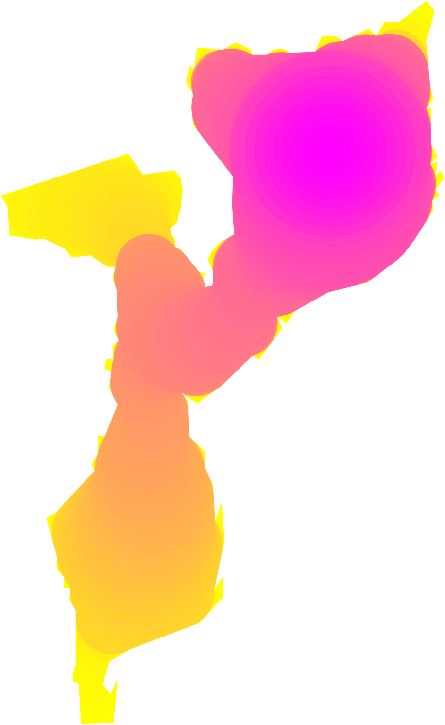
6 Theoretical Tools
Our algorithm in the previous section produces a sequence of inscribed shapes . We woud like to analyze how close they are to optimal. To do that, we first establish some theoretical tools that will help us analyze the behavior of our algorithm. These tools bridge the gap between the definition of necks and the medial axis.
6.1 Medial Axis Necks
Since our algorithm is derived jointly from the medial axis and the concept of necks, we create a generalized definition for necks based on the medial axis transform. From this definition, we can quantify the size of multiple necks as well as their locations (see Figure 6). This will allow us to prove results that are not possible to state with Definition 3.3.
Definition 6.1 (Generalized Necks).
is the set of that satisfy either of the following:
-
1.
is on the interior of a medial axis edge segment, and is a local minimum at .
-
2.
is on a medial axis node and there are two distinct outgoing medial axis edge segments , on which the change in in both of those directions is positive.
The size of a neck is .


Algorithmically, the computation of the necks is done by first computing the medial axis, and then iterating over its edges and nodes while checking the neck conditions. We denote the maximum neck radius by . Similarly we denote its minimum neck radius by . If a domain has no necks then we say . The maximum neck radius is not part of the previous definition of necks but will be used in Proposition 4 to give theoretical guarantees about our algorithm. A nice property of our neck definition is that it is compatible with the previous neck definition, i.e., the minimal neck radius of both are identical.
6.2 Thick Necks
While much is known about the isoperimetric profile for shapes with no necks (), much less is known when is finite. One might hope that if were in some sense large enough, we could still compute the isoperimetric profile with some confidence.
Here we define the thick neck condition which will be used in Proposition 5 to analyze the behavior of our algorithm on domains whose necks are large enough. Recall that is the largest circle inscribed in .
Definition 6.2 (Second Largest Circle).
Let the radius of the second largest circle in without replacement be
| (9) |
Definition 6.3 (Thick Neck).
A neck is thick if
| (10) |
Definition 6.4 (Thick Neck Condition).
A domain satisfies the thick neck condition if all of its necks are thick.
For examples of domains that satisfy the thick neck condition and their profiles, see Figure 12.
7 Analysis of Algorithm 1
Given the tools of the previous section, we can now analyze how the perimeter of our constructed shapes compares to that of . At the ’s where our algorithm samples , and , our bound satisfies several properties.
7.1 Theoretical analysis
By construction, Algorithm 1 produces an upper bound to the isoperimetric profile. This is because is always a feasible candidate to (IP) with . By applying Equation (7) to domains in , our bound is strictly monotonically increasing, similarly to the actual IP. Our construction also satisfies the condition in [GMT80], which states that must lie tangent to and its free boundary must have no points of singular curvature. This is because the free boundary of is made of circular arcs that start and end on and whose centers are on different edges of the medial axis. If these circular arcs intersect to form a point of singular curvature, then a non-contractable loop can be drawn in by tracing from the intersection through both edges of the medial axis, back to , implying .
We provide guarantees for when our bound is tight for any domain in . While we cannot guarantee that our bound is tight for all , by Proposition 4, we know our bound is tight for in a limited range.
Proposition 4.
Let be the connected component of that contains . Let . For any domain in , our bound for is tight for and .
Proof.
For , we know that . In this region, the remaining area in not covered by has no more necks. Thus the problem reduces to the case with no necks, on which our algorithm produces tight bounds. For proof of the latter range of values, see Appendix LABEL:proof:earlyT. ∎
While Proposition 4 does not cover the entire IP, it applies to any domain in regardless of the presence or size of necks. To achieve this result, this proposition uses , a quantity that is not defined in prior work.
Application of Proposition 4 is demonstrated in Figure 7. We compute our upper bound to the IP by Algorithm 1 on the Candy domain. Its profile is depicted between two events: the area of the “max inscribed circle” , and the “max area” . We apply Proposition 4, which tells us that our medial axis bound for the IP is tight to the left of the “Conservatively tight” purple event line and to the right of the “Minimal Neck” purple event line. For values of between the two purple lines, we upper-bound the IP.

Given some assumptions on the domain , we show that our IP bound exactly recovers the IP.
Proposition 5.
If grows only continuously except when transitioning to being disconnected, then for that satisfy the thick neck condition, our bound is tight for all .
Intuitively, this is because the smallest perimeter cost for having a disconnected is larger than the cost for continuing to grow via limited reconstructions. For proof, see §LABEL:proof:bigneck. Proposition 5 allows us to compute the exact isoperimetric profile for domains satisfying the thick neck condition. We show in §8.3 examples of domains satisfying this condition and that while previous methods of computing the isoperimetric profile are not tight, our method provides the exact profile for this larger class of domains.
7.2 Empirical Quality Improvements


Following Equation (8) we compute by the union of floating precision polygons. This sometimes introduces artifacts like holes, or jagged boundary at a scale that is invisible. While seemingly negligible, many holes or jagged regions add up to significantly increase the perimeter thus loosening our upper bound. This is solved easily by some basic post processing. First we remove all holes in , then we perform morphological closing with a ball of small radius, and lastly we intersect it with to make it feasible again. These steps are summarized in Algorithm 2. Figure 8 shows the change in before and after post processing. Figure 9 demonstrates the difference in the IP with and without post processing.
We also perform a repair step to the upper bound obtained by direct computation of . Since changes discontinuously with for domains with necks, this leaves gaps in the IP. An example of this discontinuous transition is visualized in Figure 9. The discontinuous change happens due to the creation of a new disconnected point in . will instantly include a circle centered on of radius , which abruptly increases area and perimeter. We detect when the number of disconnected regions in changes, and compute as the center of the bounding box of the smallest area component of . We then inflate a disk centered at from radius to . This procedure continuously fills in the IP bound and is illustrated in Figure 9.

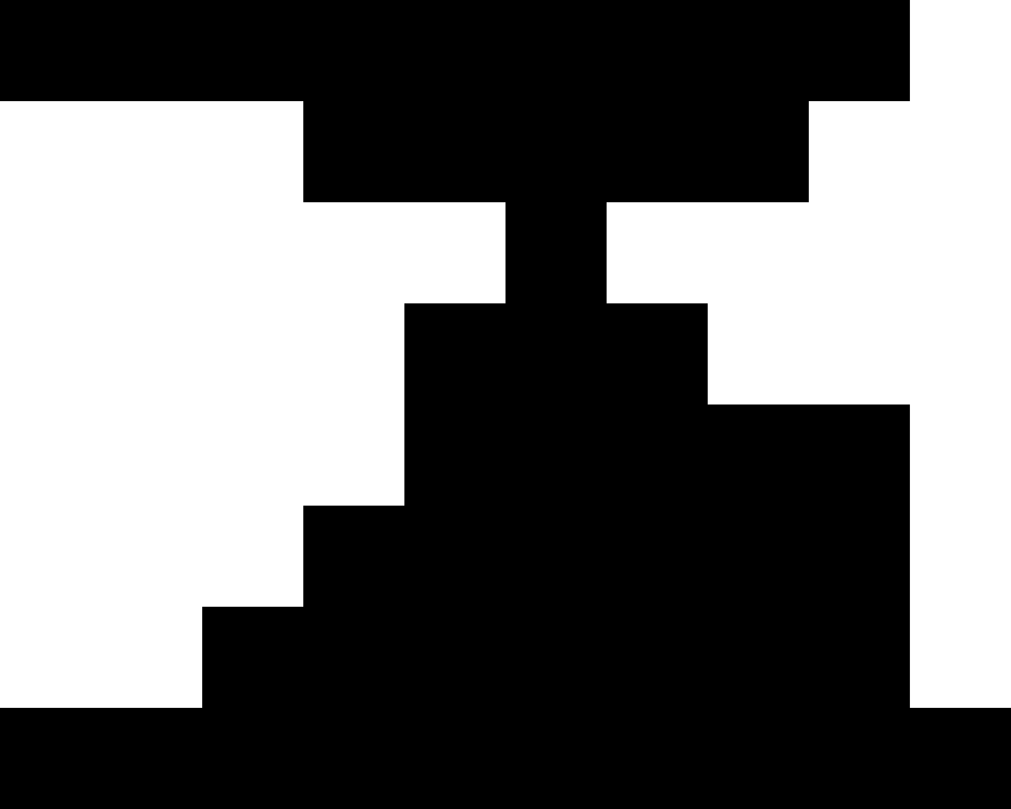
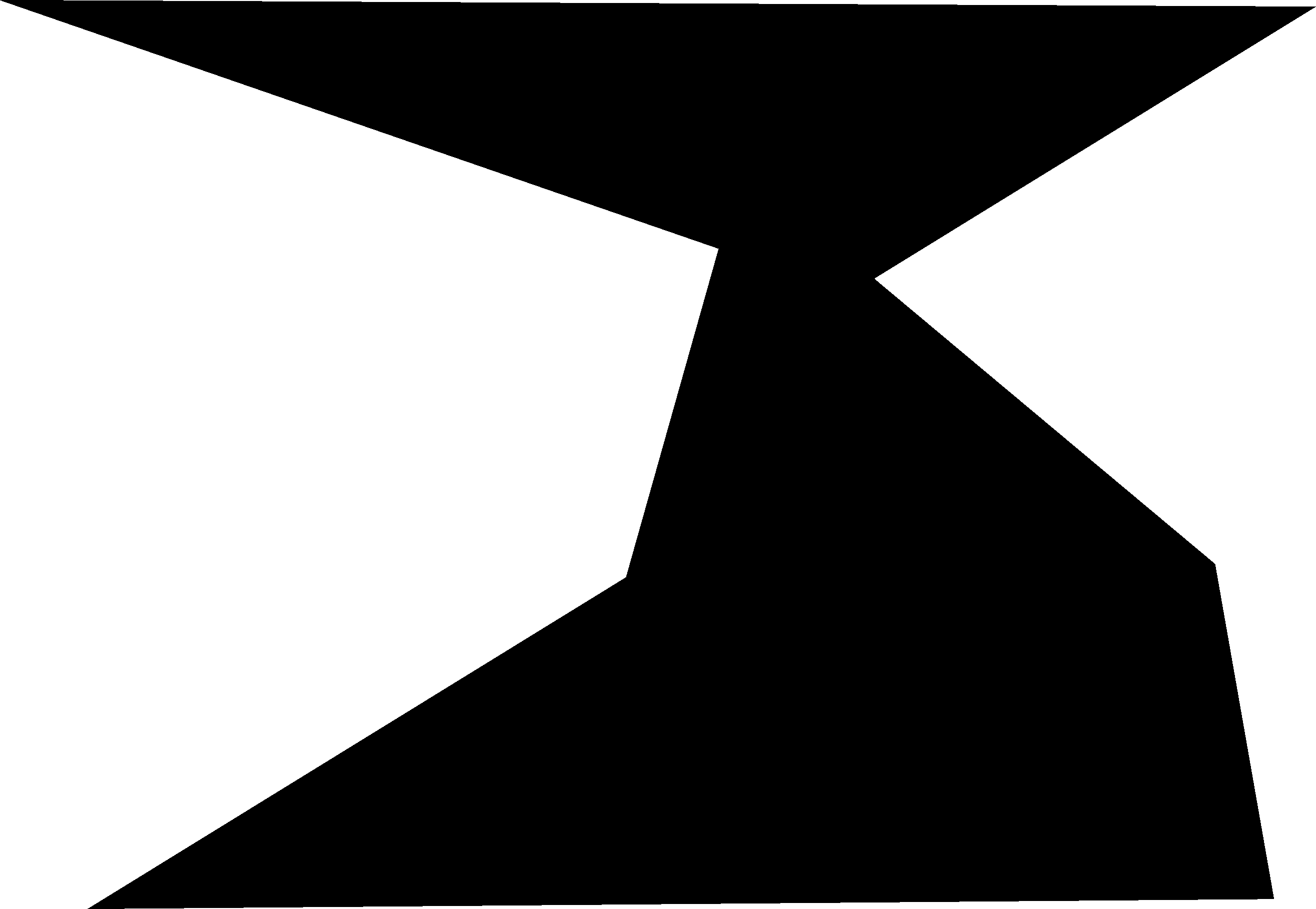
8 Experiments and Results
8.1 Comparison Methods
We compare our algorithm against the few existing computational approaches to the isoperimetric profile. First we compare Algorithm 1 with direct morphological opening. While both generate upper bounds, direct opening has much fewer guarantees and generally produces a looser bound. Next we compare with the TV approach [DLSS19] which generates lower bounds. In theory, it generates the convex lower envelope of the IP.
Code for our algorithm, figure generation, and all parameters used can be found in supplementary materials. We show profiles starting from the area of the maximum inscribed circle because the profile before then is uninformative.
8.1.1 Modification to comparison method
For comparisons with TV [DLSS19] we use a modification of their code that significantly improves their lower bound. Their algorithm hinges on the use of total variation (TV) on indicator functions as a measurement of perimeter. Their discretized TV comes from [CDPP16], which we find converges poorly to perimeter. Instead, we implement a discretization based on smoothed second order finite differences:
| (11) |
The total variation is then . A comparison of the different discretizations at perimeter estimation are shown in Figure 10. We also tested a smoothed third order finite difference gradient but find that the second order gradient achieves the closest perimeter estimate by far . We use this modified TV for all comparisons with [DLSS19]. We sometimes obtain results where the lower bound intersects the upper bound. This is because even our modified TV does not exactly converge pointwise to continuous TV. Design of such a discretization is the subject of active research and is a challenge with TV-based algorithms more broadly.


8.2 No Neck Domains
On no neck domains both the morphological opening procedure and our medial axis traversal will produce the exact isoperimetric profile. This is depicted in Figure 11. We test on a star domain Star as well as a non-star, no neck domain no-neck-J. We choose which computes most of, but not the entire, profile. This is why our profile stops before the maximum area is reached. The total variation lower bound roughly follows the convex lower envelope of our profile, but overshoots in a few regions. As a lower bound, it leaves slack room, while our algorithm is exact.
Note that the choice of is specific to the domains we tested on. As roughly corresponds to the smallest length scale of a domain our IP bound will capture, a smaller domain requires a smaller .
8.3 Thick Neck Domains
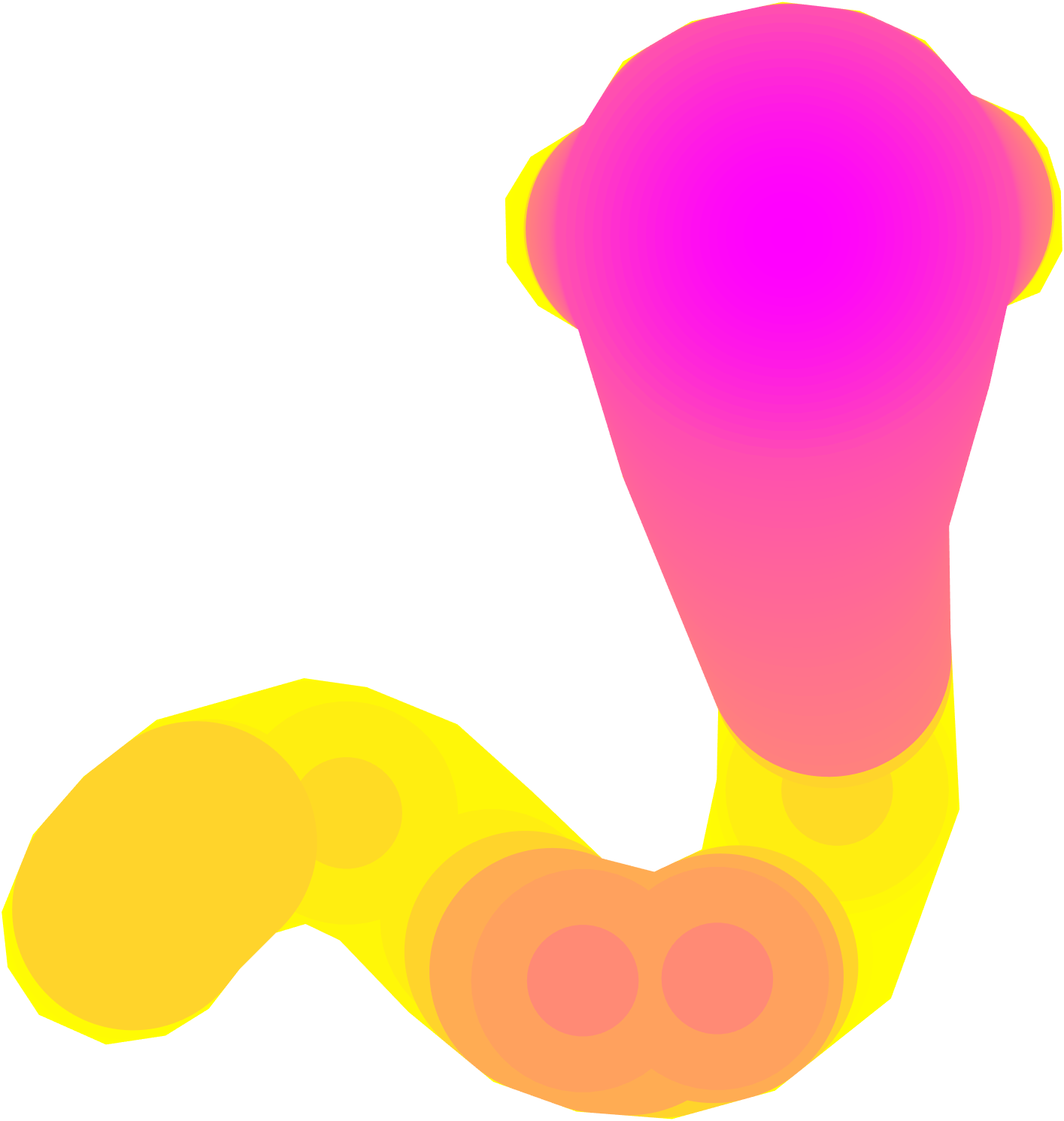
On thick neck domains our algorithm computes the exact IP, while morphological opening computes a much looser upper bound, and total variation computes the convex lower envelope of the profile. This is demonstrated in Figure 12 on the Jellyfish, Hourglass, and Worm domains. Note that the “Minimal Neck” area, , is often very close to the maximum area. Prior methods would only be able to compute the exact profile in the limited region from to , while our method computes the entire profile. Due to the prescence of necks, direct morphological opening produces much worse upper bounds than our method.
8.4 General Domains
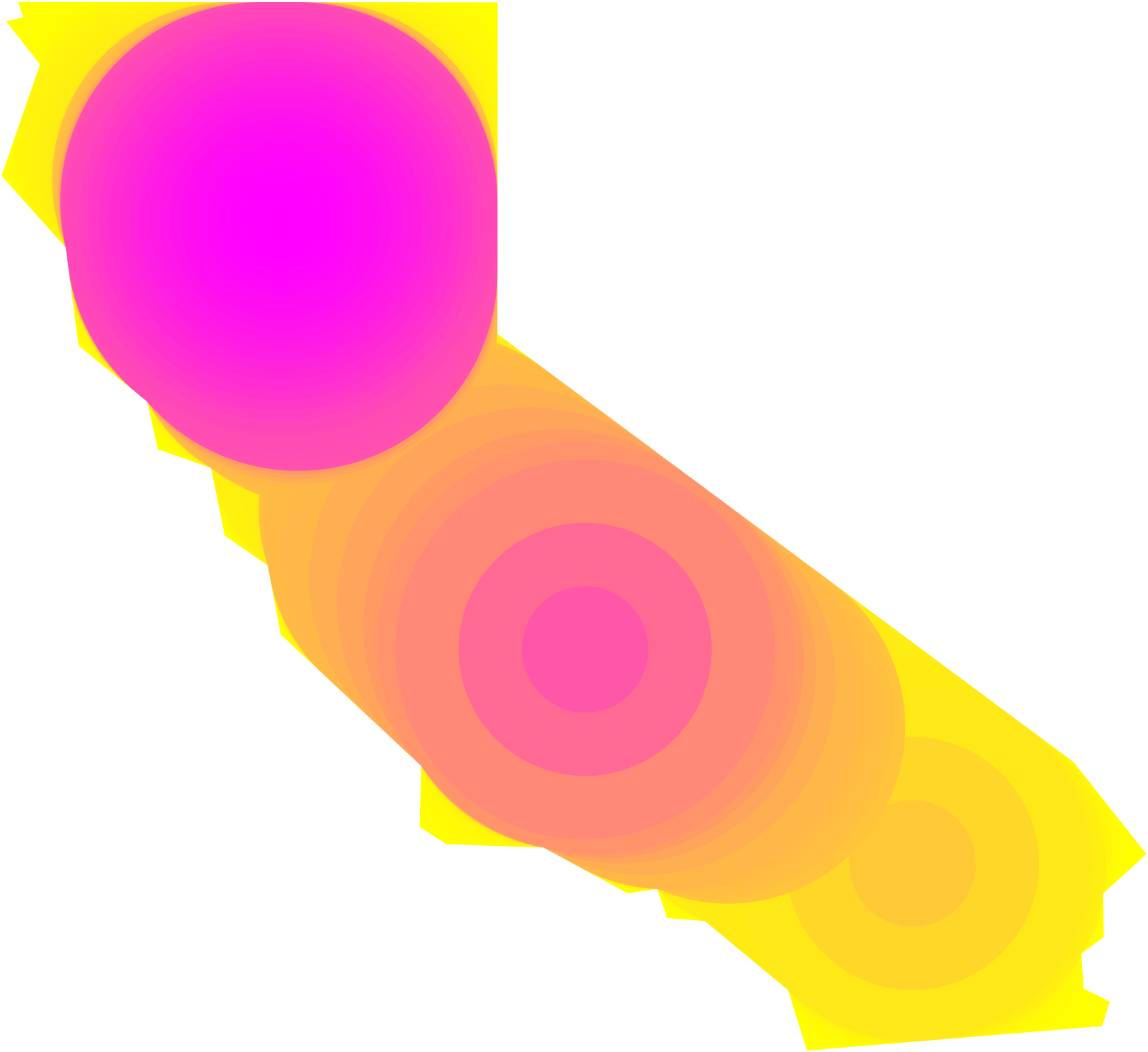
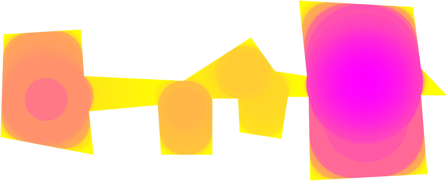
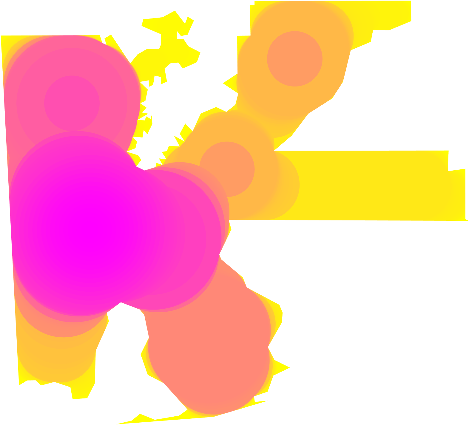
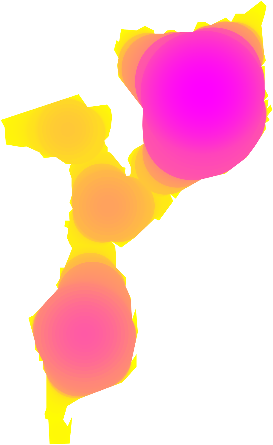
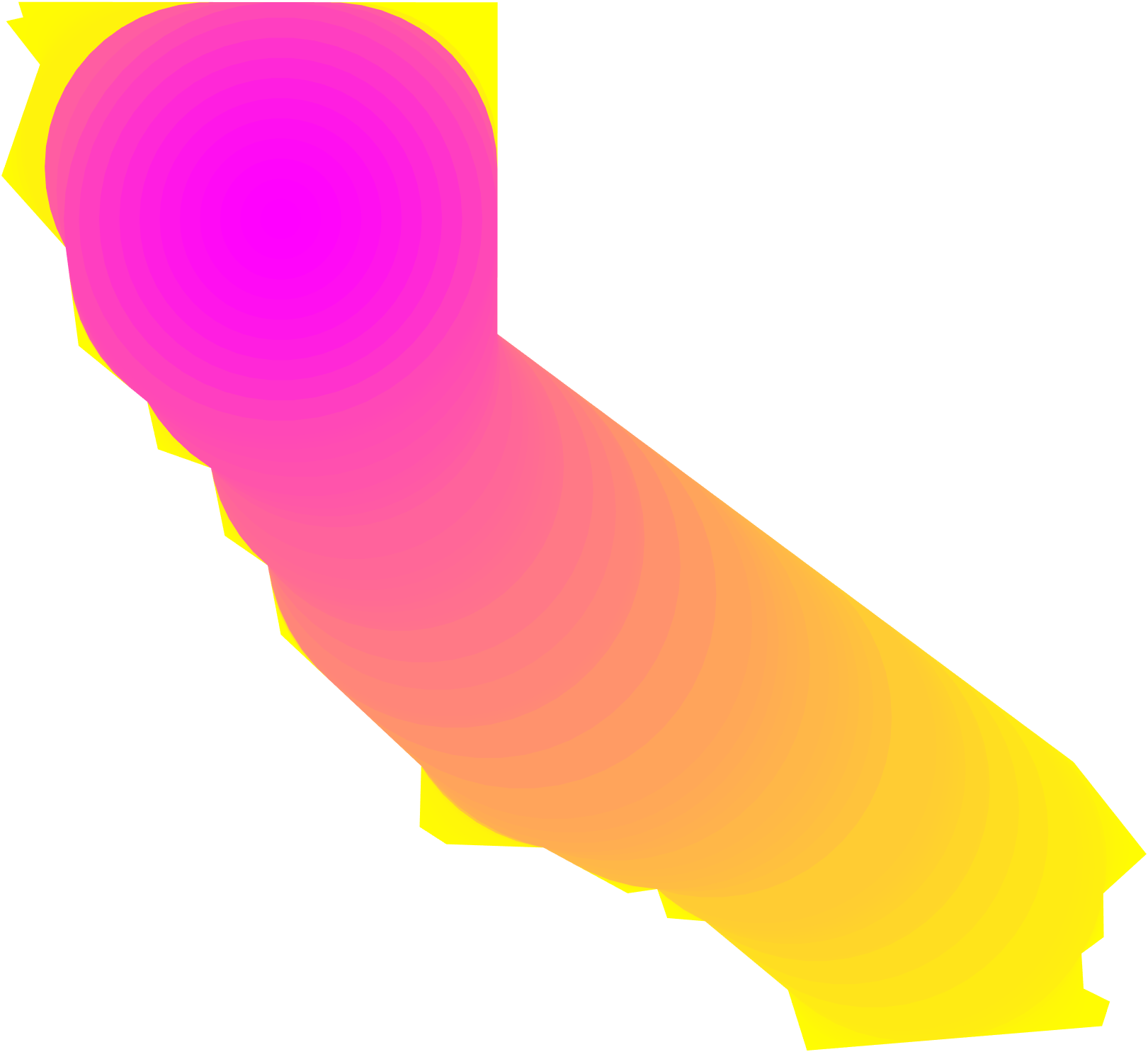
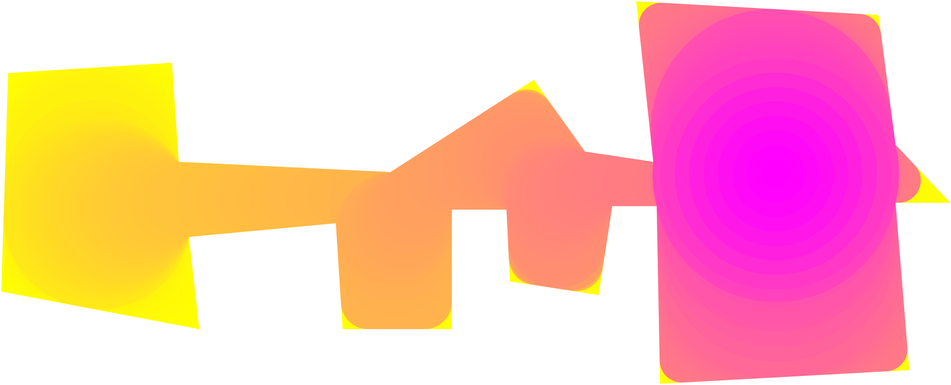
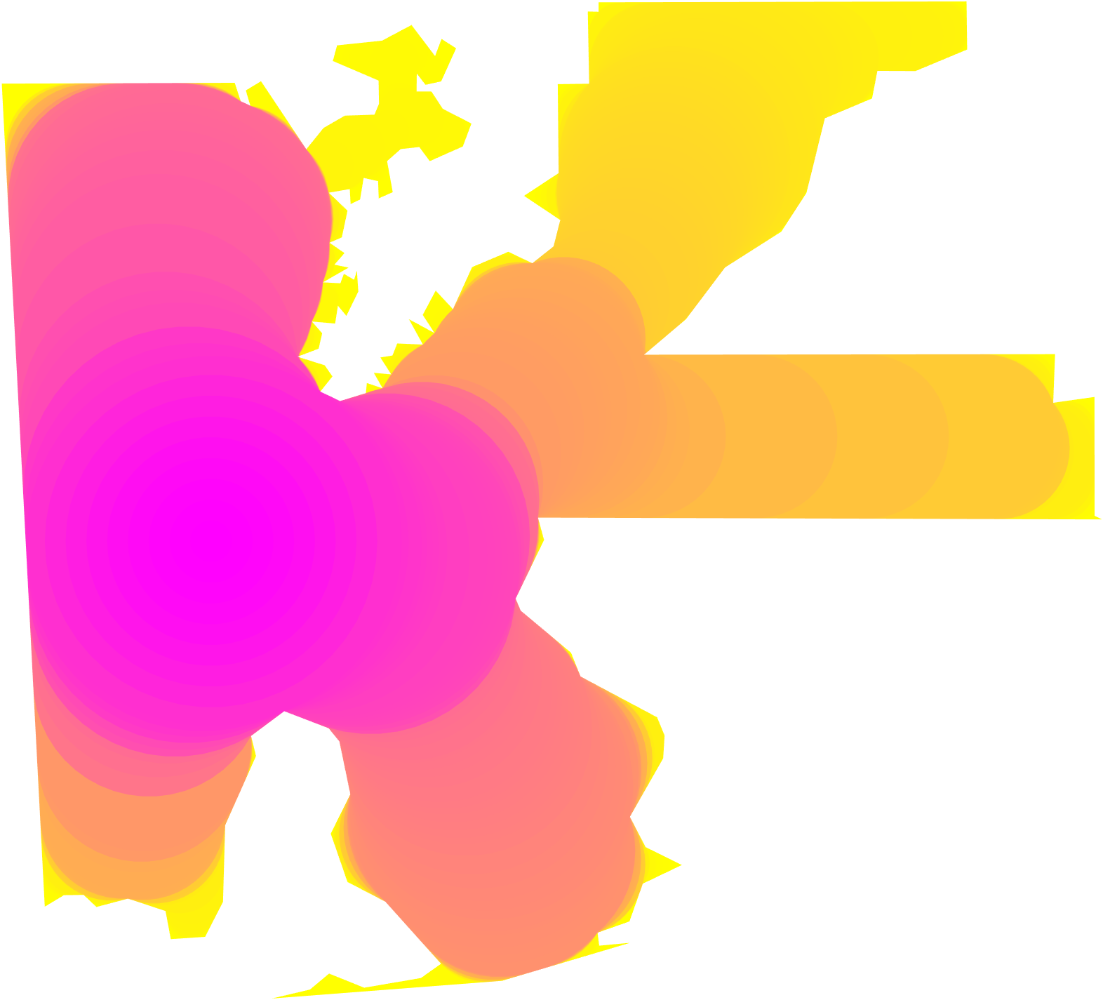
We test on a set of geographic and hand drawn data. Maps of Alabama, California, Delaware, and District 1 of Alabama were obtained from [FIP20]. A map of Mozambique was obtained from [Vem20]. In addition, we create a drawing, Boxes, to test on. Alabama, California, and Delaware satisfied the thick neck condition while District 1, Mozambique, and Boxes do not. Our profiles for these domains are shown in Figure 13. Our bound computes the exact IP for all on Alabama, California, and Delaware. [DLSS19] continues to provide convex lower envelopes with slack and an occasional intersection with the upper bound due to imperfect discretization. This lower bound is particularly loose, on Alabama, and California revealing a significant gap for most of the profile. Morphological opening produces upper bounds as well, but are loose compared to our medial axis based approach and has no theoretical guarantees except for a small region on the tail of the profile.
On the District 1, Mozambique, and Boxes domains, we use Proposition 4 to compute “Conservatively tight” and “Minimal Neck” events that allow us to guarantee our bound is tight on a larger range of values. For both District 1, and Mozambique, our algorithm produces much tighter upper bounds than morphological opening. An exception occurs on Boxes, where the morphological opening produces a tighter bound. This is explained by the fact that the optimal is disconnected for much of the profile, while our algorithm by construction only produces connected polygons. For this reason it would be worthwhile to explore using disconnected medial axis reconstructions based on a criteria like the thick neck condition. Further exploration of disconnected limited reconstructions is discussed in §LABEL:sec:discuss and left to future work.
8.5 Aggregate Profile
By combining the bounds and guarantees provided in this paper and those of [DLSS19, LS19], we compute the envelope inside which the isoperimetric profile must lie. This is visualized in Figure 14. We find that this produces a relatively narrow region of uncertainty where the IP is unknown. This visualization also makes clear the rich space of multi scale behaviors that different domains can have.
For example, consider the Jellyfish (brown). It consists of a large cap region which has mostly low resolution features, followed by several tendrils that require high resolution data to capture. This is reflected in its isoperimetric profile where it starts shallow for most of the area, before sharply veering up to have one of the largest perimeters in this figure. Delaware (bright green) demonstrates similar behavior to a lesser extent. It starts with a shallow profile indicating its coarse lower portion, before its profile curves upwards to capture the high resolution details of its upper quarter. Delaware requires less high resolution data to capture than the Jellyfish, however, as indicated by its profile sitting below that of the Jellyfish. Our results with the isoperimetric profile make it possible to computationally and numerically compare these domains’ multi-scale properties.


8.6 Runtime
A list of runtimes for our experiments is provided in Table LABEL:table:timings. The runtime of our algorithm depends most strongly on number of vertices , and loosely on other parameters , , and . For morphological opening, the runtime depends primarily on the number of samples of the IP that are computed. For all times listed, we sample 100 values of the IP. For TV, runtime depends on the number of samples of the IP that are computed as well as the pixel resolution used to rasterize the polygon. We compute 20 samples of the TV IP and use 100 vertical pixels for the rasterization.
References
- [AVP99] Arinyo R. J., Vidal L. P., Pastó J. V.: Computing the medial axis transform of polygonal domains by tracing paths.
- [BES49] BESICOVITCH A.: A variant of a classical isoperimetric problem. Quarterly Journal of Mathematics (01 1949), 84–94. doi:10.1093/qmath/os-20.1.84.
- [Blu67] Blum H.: A Transformation for Extracting New Descriptors of Shape. In Models for the Perception of Speech and Visual Form, Wathen-Dunn W., (Ed.). MIT Press, Cambridge, 1967, pp. 362–380.
- [BNNS19] Bar-Natan A., Najt L., Schutzman Z.: The gerrymandering jumble: Map projections permute districts’ compactness scores. arXiv:1905.03173 (2019).
- [BS20] Barnes R., Solomon J.: Gerrymandering and compactness: implementation flexibility and abuse. Political Analysis (2020).
- [CDPP16] Chambolle A., Duval V., Peyré G., Poon C.: Geometric properties of solutions to the total variation denoising problem. Inverse Problems 33, 1 (dec 2016), 015002.
- [CFG12] Croft H., Falconer K., Guy R.: Unsolved Problems in Geometry: Unsolved Problems in Intuitive Mathematics. Problem Books in Mathematics. Springer New York, 2012. URL: https://books.google.com/books?id=rdDTBwAAQBAJ.
- [DLSS19] DeFord D. R., Lavenant H., Schutzman Z., Solomon J.: Total variation isoperimetric profiles. SIAM J. Appl. Algebra Geom. 3 (2019), 585–613.
- [DT18] Duchin M., Tenner B. E.: Discrete geometry for electoral geography, 2018. arXiv:1808.05860.
- [Ehr82] Ehrenburg K.: Studien zur hessnng der horizontalen gliederung von erdräuinen. In Verhandlungen derPhysikalisch-medizinische Gesellschaft zu Würzburg (1982), p. 41–92.
- [FIP20] FIPS: State FIPS Code Listing, 2020. URL: https://www.mcc.co.mercer.pa.us/dps/state_fips_code_listing.htm.
- [GMT80] Gonzalez E., Massari U., Tamanini I.: On the Regularity of Boundaries of Sets Minimizing Perimeter with a Volume Constraint. Libera Universita di Trento. Dipartimento di Matematica, 1980. URL: https://books.google.com/books?id=jPYcrgEACAAJ.
- [GW96] Gordon C., Webb D.: You can’t hear the shape of a drum. American Scientist 84, 1 (1996), 46–55.
- [Kar20] Karavelas M.: 2D segment Delaunay graphs. In CGAL User and Reference Manual, 5.0.2 ed. CGAL Editorial Board, 2020. URL: https://doc.cgal.org/5.0.2/Manual/packages.html##PkgSegmentDelaunayGraph2.
- [KKKng] Kaufman A., King G., Komisarchik M.: How to measure legislative district compactness if you only know it when you see it. American Journal of Political Science (Forthcoming).
- [Kno17] Knopp K.: Einheitliche erzeugung und darstellung der kurven von Peano, Osgood und Koch. Arch. Math. Phys. 26 (1917), 103–115.
- [Lan77] Lantuéjoul C.: Sur le modèle de Johnson-Mehl généralisé. In Internal Report of the Centre de Morph. Math. (1977).
- [LNS17] Leonardi G., Neumayer R., Saracco G.: The Cheeger constant of a Jordan domain without necks. Calculus of Variations and Partial Differential Equations 56 (11 2017), 164. doi:10.1007/s00526-017-1263-0.
- [LS19] Leonardi G. P., Saracco G.: Minimizers of the prescribed curvature functional in a jordan domain with no necks. arXiv preprint arXiv:1912.09462 (2019).
- [PP91] Polsby D. D., Popper R. D.: The third criterion: Compactness as a procedural safeguard against partisan gerrymandering. Yale Law & Policy Review 9, 2 (1991), 301–353.
- [Ros05] Ros A.: The isoperimetric problem. Clay Math. Proc. 2 (01 2005).
- [Ser00] Serra J.: Cours de morphologie mathematique. http://www.cmm.mines-paristech.fr/˜serra/cours/index.htm, 2000.
- [Sul12] Sulovskỳ M.: Depth, Crossings and Conflicts in Discrete Geometry. Logos Verlag Berlin, 2012. URL: https://books.google.com/books?id=0Q9mbXCQRyoC.
- [SZ98] Stredulinsky E., Ziemer W.: Area minimizing sets subject to a volume constraint in a convex set. Journal of Geometric Analysis 7 (12 1998). doi:10.1007/BF02921639.
- [Vem20] Vemaps: Mozambique Map by Vemaps.com, 2020. URL: https://vemaps.com/mozambique/mz-01.
- [VF83] Virgil., Fitzgerald R.: The Aeneid. New York: Random House, 1983.
- [voMSRP11] State of Minnesota Special Redistricting Panel: Order a11-152. http://www.mncourts.gov/Documents/0/Public/Court_Information_Office/2011Redistricting/A110152Order11.4.11.pdf, 11 2011.