Megawatt peak power from a Mamyshev oscillator: supplementary material
Abstract
This document provides supplementary information to Megawatt peak power from a Mamyshev oscillator. We show numerical results on maximum performance of the experimental Mamsyshev oscillator design and discuss performance limits. We provide numerical results that show the importance of a Gaussian filter profile for obtaining high-quality, high-energy pulses. Finally, experiments on starting a linear cavity are described.
pacs:
(060.2310) Fiber optics; (190.0190) Nonlinear optics; (060.4370) Nonlinear optics, fibers.I Simulation result for the highest energy pulses
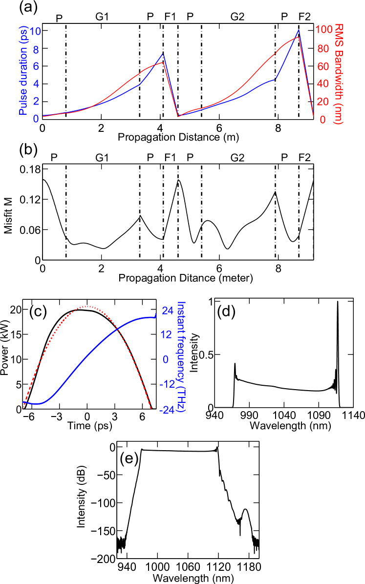
Fig. 1 shows the simulation result for the highest pulse energy output (190 nJ) for the same cavity design as the experiment. The spectral breathing ratio is 26 (Fig. 1 (a)). Compared with the 50-nJ example, the pulse shape deviates more from the parabola during the whole roundtrip (Fig. 1 (b)). The chirp of the pulse is consequently not linear, and its deviation increases for higher pulse energy (Fig. 1 (c)). That said, the pulse is still coherent, and the 150-nm bandwidth (Fig. 1 (d)) corresponds to <20 fs transform-limited pulses, which could be obtained with a pulse compressor that controls higher-order dispersion. On a logarithmic scale, the spectrum shows the formation of a parasitic Raman peak (Fig. 1 (e)). Understanding these two factors - breakdown of the parabolic shape, and formation of Raman - and how to manage them will determine the ultimate limits of the Mamyshev oscillator.
II Effect of the filter shape
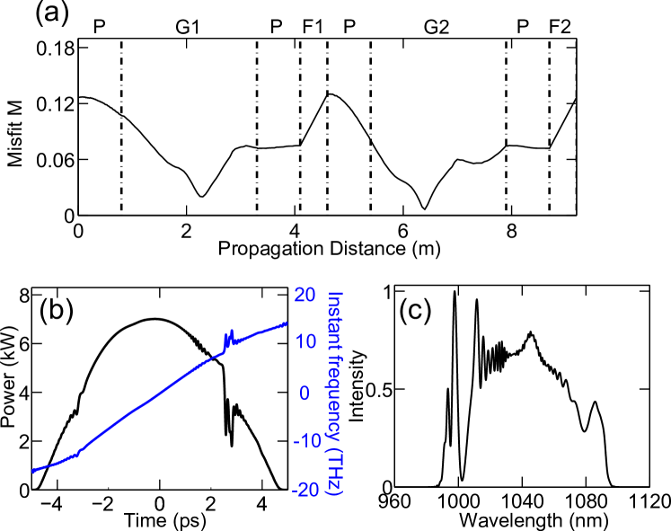
Using a Gaussian filter is evidently important for the peak performance and pulse quality. For the ring cavity, when we replace the Gaussian filters (4-nm bandwidth) with super-Gaussian shape filters (4-nm bandwidth) in the simulation, the highest achieved pulse energy is 40 nJ, which is much lower than the results using Gaussian filters (Fig. 2).
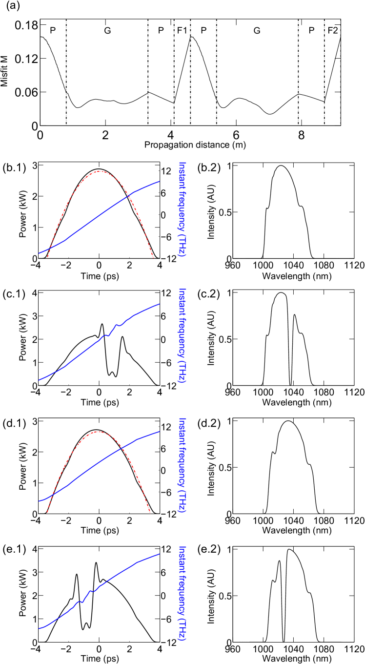
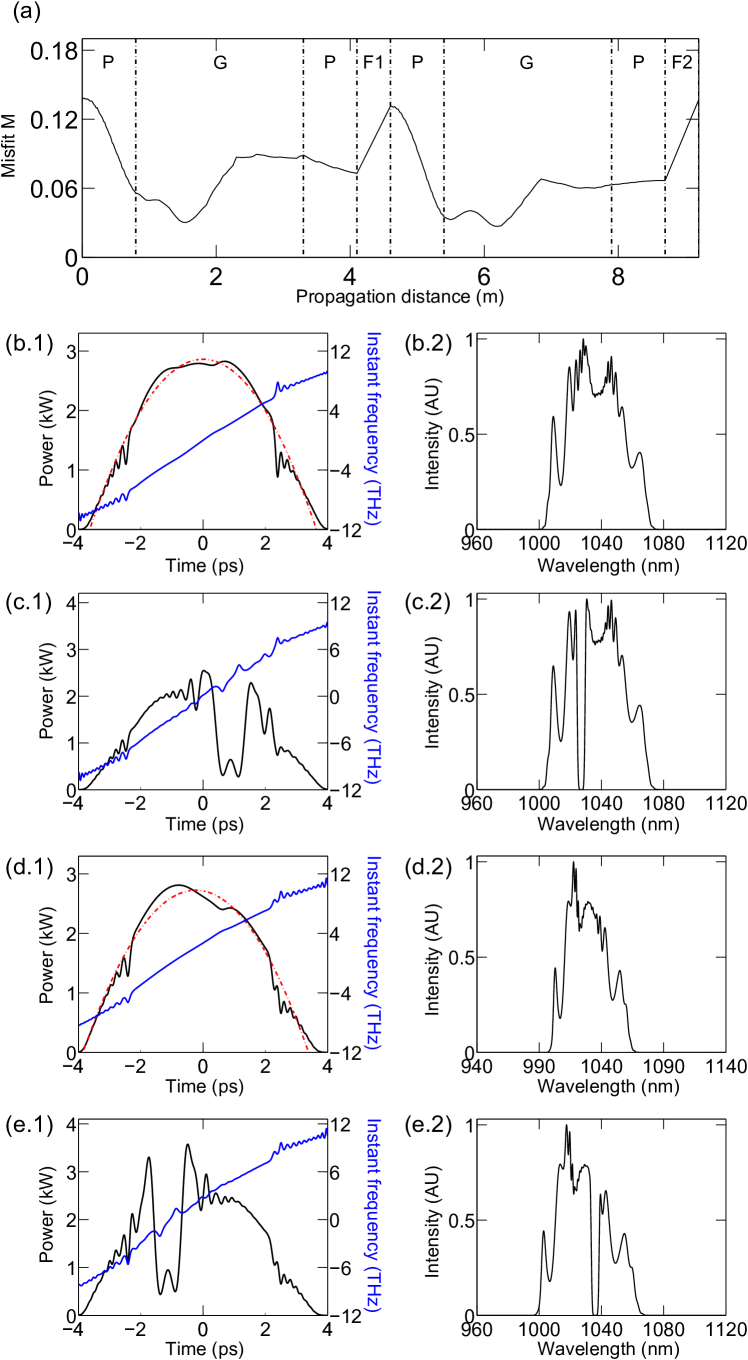
The simulations indicate that the use of filters that do not have Gaussian transmittance bands reduces the stable pulse energy and yields structure on the spectrum. Furthermore, the Gaussian filter’s improvement of the output chirped pulses’ smooth parabolic shape, and the smoothness of the spectra, is an important feature that should improve the pulses’ use as a seed for low-distortion fiber amplifiers. Fig. 3 and Fig. 4 show the difference between the linear cavity output using Gaussian filter and super-Gaussian filter with similar bandwidth (4nm FWHM).
III Experiments on starting
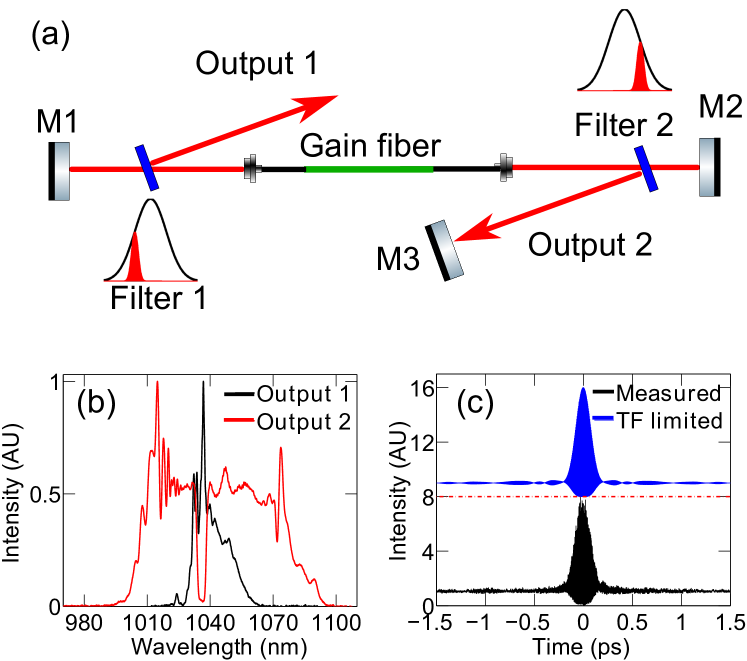
To investigate the starting dynamics, we built a similar linear oscillator (Fig. 5 (a)). Two mirrors (M1 and M2), two bandpass filters (4-nm near super-Gaussian interference filters biased to longer and shorter wavelengths with respect to the gain spectrum) and the fiber segments form the Mamyshev cavity. The rejected beams from these filters are taken as the outputs. When seeded by short pulses as described in the main text, the linear oscillator behaves like the ring, but the maximum pulse energy is lower due to several practical problems. For example, simulations show that output performance is limited compared to the ring due to the super-Gaussian filter shape. Short-pulse generation can also be started by placing a mirror (M3) at one of the outputs to direct the rejected light back into the oscillator. This is consistent with previously reported work Julijanas15 ; RegelskisPatent . Adding this mirror creates two coupled cavities: the Mamyshev cavity with two spectral filters, described above, and a cavity that can oscillate on a CW basis within the pass-band of filter 1. The Mamyshev cavity only oscillates for high peak power and does not support CW operation, while the opposite is true for the coupled CW cavity formed by M1 and M3. With the feedback cavity coupled, we observe that a pulse train in the Mamyshev typically starts after 10 seconds of operation. The spectra recorded from the two outputs are shown in Fig. 5 (b), and are very similar to the spectra produced with seed pulses. The spectrum from output 2 (13 nJ) is wider than the spectrum from output 1 (6.5 nJ). The large bandwidth difference between the two outputs is a result of the filters not being symmetrically distant from the peak of the gain spectrum. The measured autocorrelation for the dechirped output 1 (using a grating pair compressor) and the corresponding transform-limited pulses (125-fs duration) are shown in Fig. 5 (c). The close agreement implies that the chirp of the pulses exiting the cavity must be nearly linear. In contrast, the pulse from output 2 cannot be dechirped to the transform limit due to uncontrolled nonlinear phase accumulation. This is likely a consequence of the non-Gaussian filter profile.
By observing the cavity output prior to starting, we infer that self-starting in the coupled linear cavity Mamyshev oscillator is the result of spectral broadening of extreme lasing spikes that result from relaxation oscillations within the coupled cavity. We observe bunches of nanosecond-duration pulses from output 1, whose duration and hundred-s temporal separation is consistent with relaxation oscillation in the CW cavity. These relaxation oscillations are only observed when the loss of the CW cavity is sufficiently large; when M3 is optimally-aligned, self-starting is not observed. When self-starting is observed, it is repeatable: if the cavity is blocked and unblocked, pulsation returns within 10 seconds. We attribute the self-starting to spectral broadening of the nanosecond-duration spikes. For rare extreme-amplitude spikes, relatively broad initial bandwidth and nonlinear spectral broadening are sufficient for them to couple into the Mamyshev cavity and initiate pulsation. Once the Mamyshev cavity has started, it is indefinitely stable in the continued presence of the coupled CW cavity, which is attractive for practical applications.
References
- (1) K. Regelskis, G. Raciukaitis, “Method and generator for generating ultra-short light pulses,” WO2016020188 A1.
- (2) Personal communication with J. Zeludevicius, Center for Physical Sciences & Technology (CPST) Savanoriu Ave. 231, LT-02300 Vilnius, Lithuania (2015).