Melt-Mixing by Novel Pitched-Tip Kneading Disks
in a Co-Rotating Twin-Screw Extruder
Abstract
Melt-mixing in twin-screw extruders is a key process in the development of polymer composites. Quantifying the mixing performance of kneading elements based on their internal physical processes is a challenging problem. We discuss melt-mixing by novel kneading elements called “pitched-tip kneading disk (ptKD)”. The disk-stagger angle and tip angle are the main geometric parameters of the ptKDs. We investigated four typical arrangements of the ptKDs, which are forward and backward disk-staggers combined with forward and backward tips. Numerical simulations under a certain feed rate and screw revolution speed were performed, and the mixing process was investigated using Lagrangian statistics. It was found that the four types had different mixing characteristics, and their mixing processes were explained by the coupling effect of drag flow with the disk staggering and pitched-tip and pressure flows, which are controlled by operational conditions. The use of a pitched-tip effectively to controls the balance of the pressurization and mixing ability.
Keywords: Polymer Processing, Twin-screw extruder, Numerical simulation, Dispersive mixing, Distributive mixing
1 Introduction
A twin-screw extruder (TSE) is widely used in various industries, including polymer processing, food processing, rubber compounding, pharmaceutical development, and processing other highly viscous materials because multiple processes, for instance, heating, melting, compounding, blending, reaction, and devolatilization, can be conducted continuously in one operation. In the plastic industry, a TSE is used to develop products with certain desired properties by compounding and blending different types of polymers, fillers, and other additives. In this process, controlling the mixing in the TSE is critical to optimize and improve the productivity and functionality of products.
The control of the mixing process is based on the design of the kneading screw element. In the past, among different kneading screws, kneading disks (KDs) were the most commonly used for general purpose compounding due to its mixing efficiency. One main geometric parameter of a KD is the disk-stagger angle that controls both the pumping capability and inter-disk leakage flow simultaneously. However, these two factors have different effects on the mixing process.
To control these two factors separately, we have proposed a novel design of a kneading screw element, called “pitched-tip kneading disk (ptKD)” (Shigeishi et al., 2006). In the ptKDs, disk tips are pitched to the screw axes in contrast to the tips that are pitched parallel to the screw axes in conventional KDs. By arranging the pitched-tip angle along with the disk-stagger angle, the pumping capability and the inter-disk leakage flow are controlled independently. This flexibility makes it possible to better control distributive mixing and dispersive mixing than with conventional KDs.
For a specific application of novel screw or barrel designs, it is difficult to optimize extrusion conditions because there are a large number of parameters including geometric and operational parameters of the device and rheological parameters of the materials, which affect the flow pattern and mixing process. It is difficult to experimentally obtain information on the flow pattern and mixing process in a TSE because TSEs are operated under severe conditions, including high temperature and high pressure; moreover, the channel in TSEs in which materials are transported is highly complicated. Numerical simulation can aid in assessing material behaviors in a TSE.
Three-dimensional fluid dynamic simulations of melt-mixing in TSE have been performed by several authors (Kajiwara et al., 1996; Yoshinaga et al., 2000; Ishikawa et al., 2000a, b, 2001, 2002; Funatsu et al., 2002; Yang and Manas-Zloczower, 1992; Cheng and Manas-Zloczower, 1998; Yao and Manas-Zloczower, 1998; Cheng and Manas-Zloczower, 1997; Bravo et al., 2000, 2004; Jaffer et al., 2000; Lawal and Kalyon, 1995a, b; Kalyon and Malik, 2007; Malik and Kalyon, 2005; Alsteens et al., 2004). It is essential to perform three-dimensional simulations to observe the material flow and the mixing process in TSE because the process is mainly dominated by the three-dimensional structure of the channel.
In this article, we investigate the flow characteristics and mixing process in melt-mixing with several types of ptKDs. We conducted three-dimensional numerical simulations of melt-mixing zone in a TSE. Material kinetics was solved with the Lagrangian method, and the characteristics of distributive and dispersive mixing in melt-mixing with several types of ptKD was investigated.
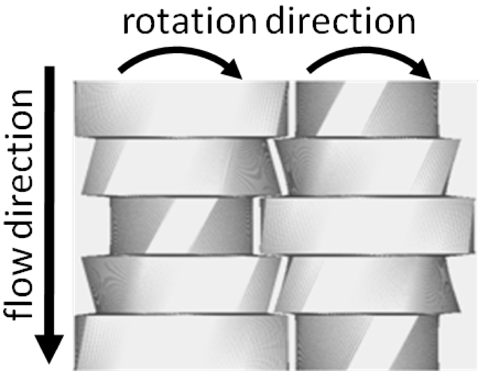
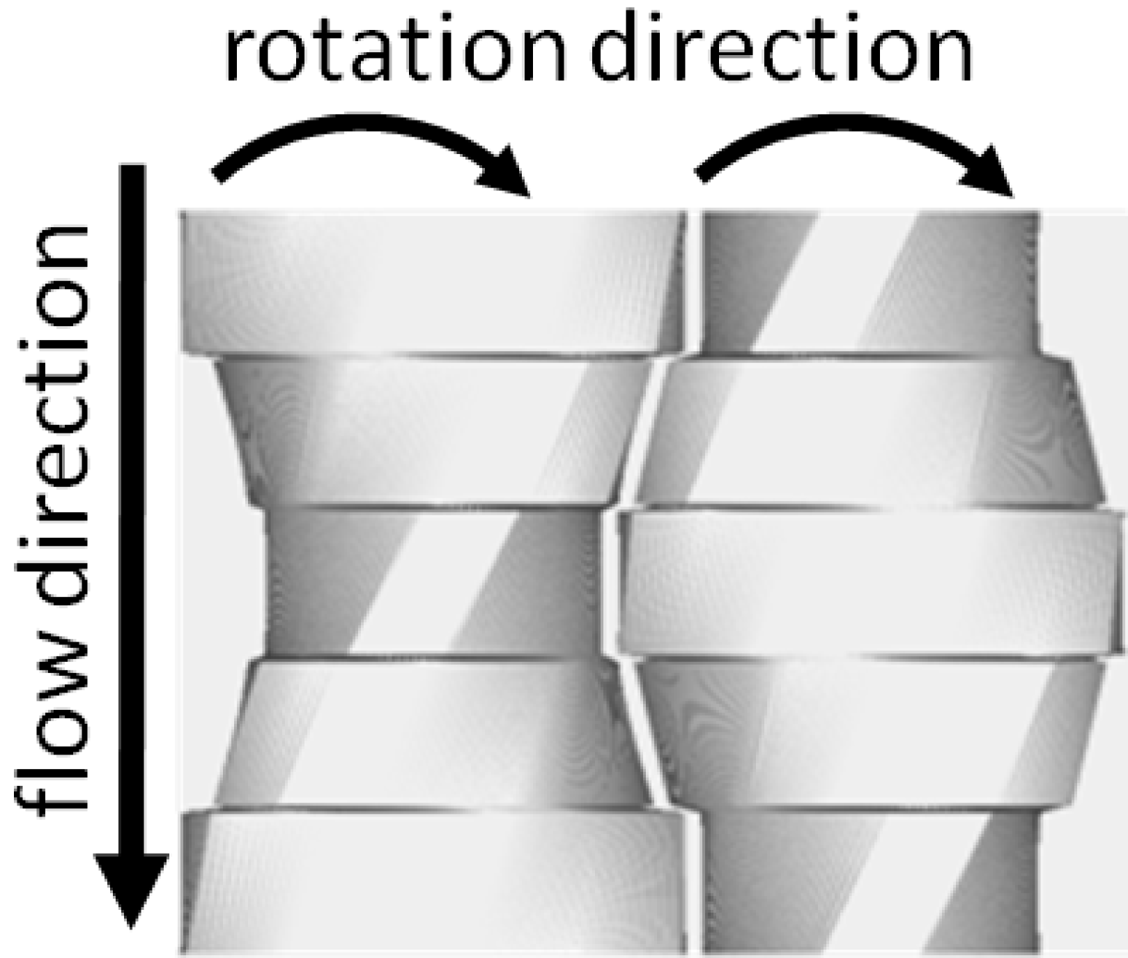
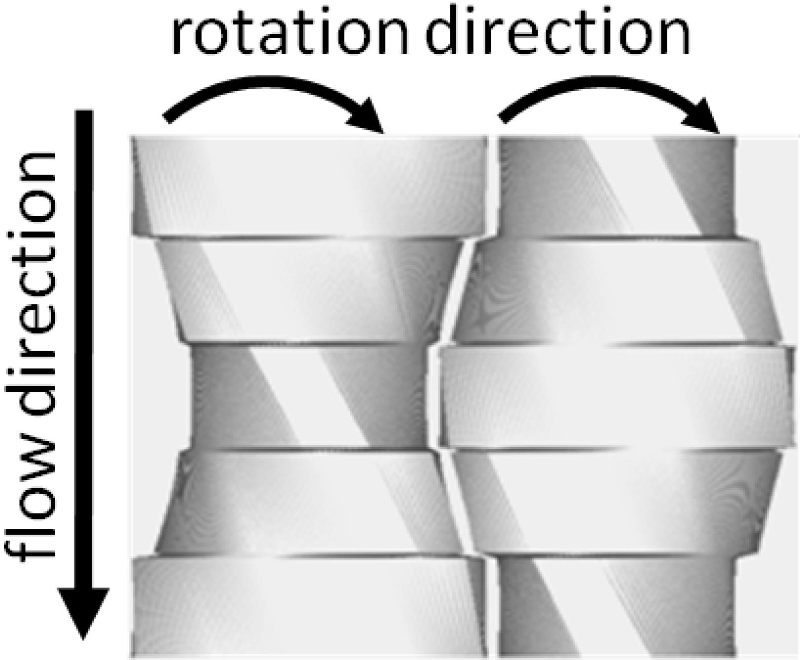
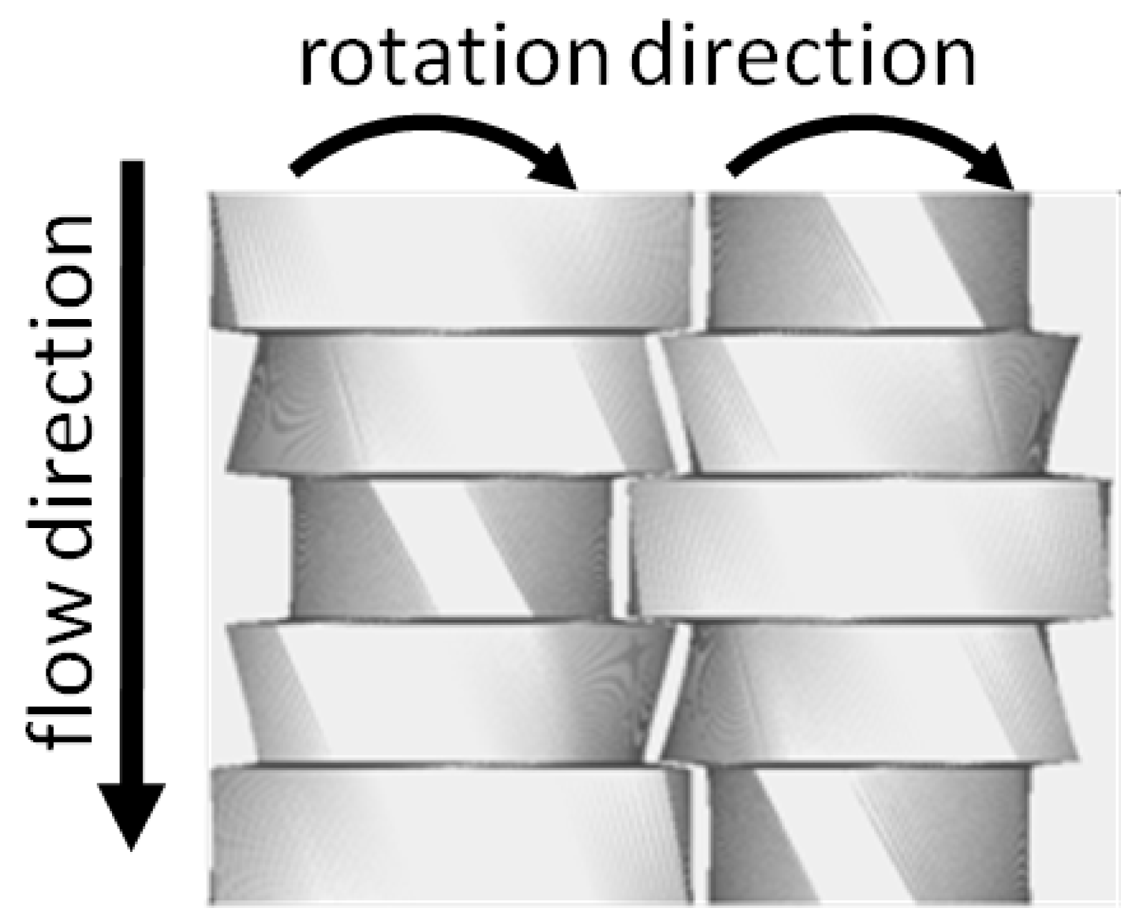
2 Pitched-tip kneading disk
One element of a ptKD is composed of several kneading blocks, like the conventional KD, but each kneading block of a ptKD has non-parallel tips to the screw axes, in contrast to conventional KDs. When a tip is pitched to pump fluid forward (backward) along the screw rotation, it is called a “forward (backward) tip”. When the disk-stagger angle is arranged to pump fluid forward (backward) along the screw rotation, it is called a “forward (backward) stagger”. According to these two main geometric characteristics, ptKDs are typically classified as one of four types: backward stagger and forward tip (Bs-Ft), forward stagger and forward tip (Fs-Ft), backward stagger and backward tip (Bs-Bt), and forward stagger and backward tip (Fs-Bt). Figure 2 shows the top views of the four typical types of ptKDs.
The four types of ptKDs in Fig. 2 are composed of five blocks of one element and are chosen for our investigation. Based on the barrel diameter mm, each self-wiping block (Booy, 1978) had a flight radius of 0.48 and a width of 0.3. Disk-stagger angles were set to for Fs-Ft and Bs-Bt, for Fs-Bt and Bs-Ft, respectively. The leads of four types of ptKDs were set to .
 (a)
(a)
|
 (b)
(b)
|
 (c)
(c)
|
 (d)
(d)
|
3 Numerical simulation
3.1 Basic equations
Our simulation focuses on the situation in which the material is fully filled in the melt-mixing zone in a TSE. The flow of the polymer melt in the TSE was assumed to be incompressible, and the Reynolds number was assumed to be much less than unity so that the inertial effects could be neglected. We considered the pseudo-steady state of mass and heat transfers under which the momentum and temperature fields instantly reach the steady state for a given channel geometry, and the time evolution of the fluid is totally governed by the screw rotation. With these assumptions, the governing equations become
| (1) | ||||
| (2) | ||||
| (3) |
where and are the hydrostatic pressure and the deviatoric stress, respectively; , , and are the mass density, the specific heat capacity, the temperature and the thermal conductivity, respectively; and is the strain-rate of the velocity field , where indicates the transpose.
3.2 Working fluid and constitutive equations
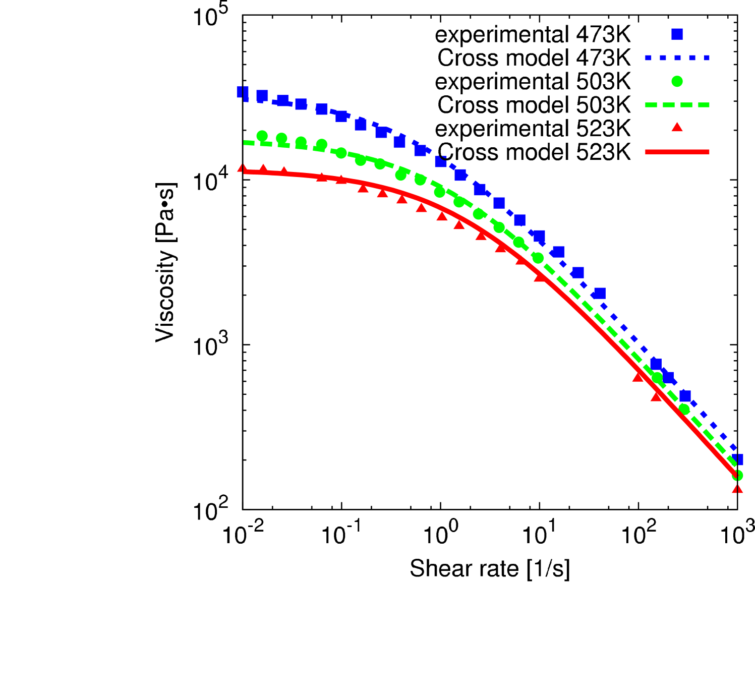
We employ a homogeneous fluid as the working fluid because we are focused on characterizing the melt-mixing of different screw geometries. The working fluid is assumed to be a viscous shear-thinning fluid that follows the Cross-exponential model:
| (4) | ||||
| (5) | ||||
| (6) | ||||
| (7) |
The parameters of the Cross-exponential model were determined by fitting function to the experimental shear viscosity of a polypropylene melt (Ishikawa et al., 2000a), as shown in Fig.2.
The mass density, specific heat capacity, and thermal conductivity were assumed to be temperature-independent in the simulation: kg/m3, J/(kgK), and W/mK, respectively.
3.2.1 Boundary conditions
The no-slip condition on the velocity at the barrel and screw surfaces is assumed. The velocities at inlet and outlet boundaries were obtained according to the same cross-sectional velocity profile under the given volumetric flow rate of cm3/s (159 kg/h). The temperatures on the barrel surface and at the inlet boundary were set to 473 K and 453 K, respectively. The natural boundary conditions for the temperature equation in the exit boundary plane and the screw surface were assigned.
3.2.2 Penalty method for the incompressibility condition
To incorporate the incompressibility condition (1) in momentum conservation (2), the penalty method is utilized: the pressure in Eq.(2) is eliminated by imposing the relation
| (8) |
with a constant (Zienkiewicz, 1977). The penalty term in the momentum conservation effectively acts as a very large bulk viscous stress; therefore, the resulting velocity field satisfies the incompressibility condition (1) in the limit as .
3.2.3 Spatial discretization and time evolution
The channel in a TSE is decomposed by the hexahedral element. The velocity and the temperature are approximated by tri-quadratic interpolation with the 27-node in each hexahedral element. The momentum equations (2) and (8) were discretized by the Galerkin finite element method. The temperature equation (3) was discretized by streamline-upwind/Petrov–Galerkin method (Brooks and Hughes, 1982; Marchal and Crochet, 1987) to stabilize the advection term.
The time evolution of the velocity and temperature fields was constructed with the converged fields for every three degrees of screw rotation. This computation was the most costly. For reference, one simulation takes about 68 hours on a computer with an Intel Core 2 Extreme processor.
3.2.4 Lagrangian point tracer
The trajectories of the passive tracers were determined based on the solved velocity field. The time evolution of the tracer density was utilized to assess the flow pattern in the melt-mixing zone with a ptKD. The set of tracer trajectories was utilized to compute the residence time distribution (Levenspiel, 1998) and to investigate the flow history and mixing process. The Lagrangian-history average of a quantity over the trajectory of th tracer is defined as
| (9) |
where and are the residence time and position of the th tracer, respectively, and is the Dirac delta distribution. The statistical distribution of characterizes the process in the melt-mixing zone.
Initially, 2000 points were uniformly distributed in a certain section relative to the axial position, which is arbitrarily set in the second disk. They were advected until they reach the outlet section. When computing the tracer advection, some tracers went out of bounds because the time resolution of the velocity field was limited. To circumvent the effect of the lost tracers on the statistics, we set the number of initial points of 2000, which ensured that a sufficient number of points reached the outlet. In our advection computation, at least 93% of the tracers reached the outlet.
4 Results and discussion
4.1 Basic characteristics of ptKDs
4.1.1 Drag ability of ptKD
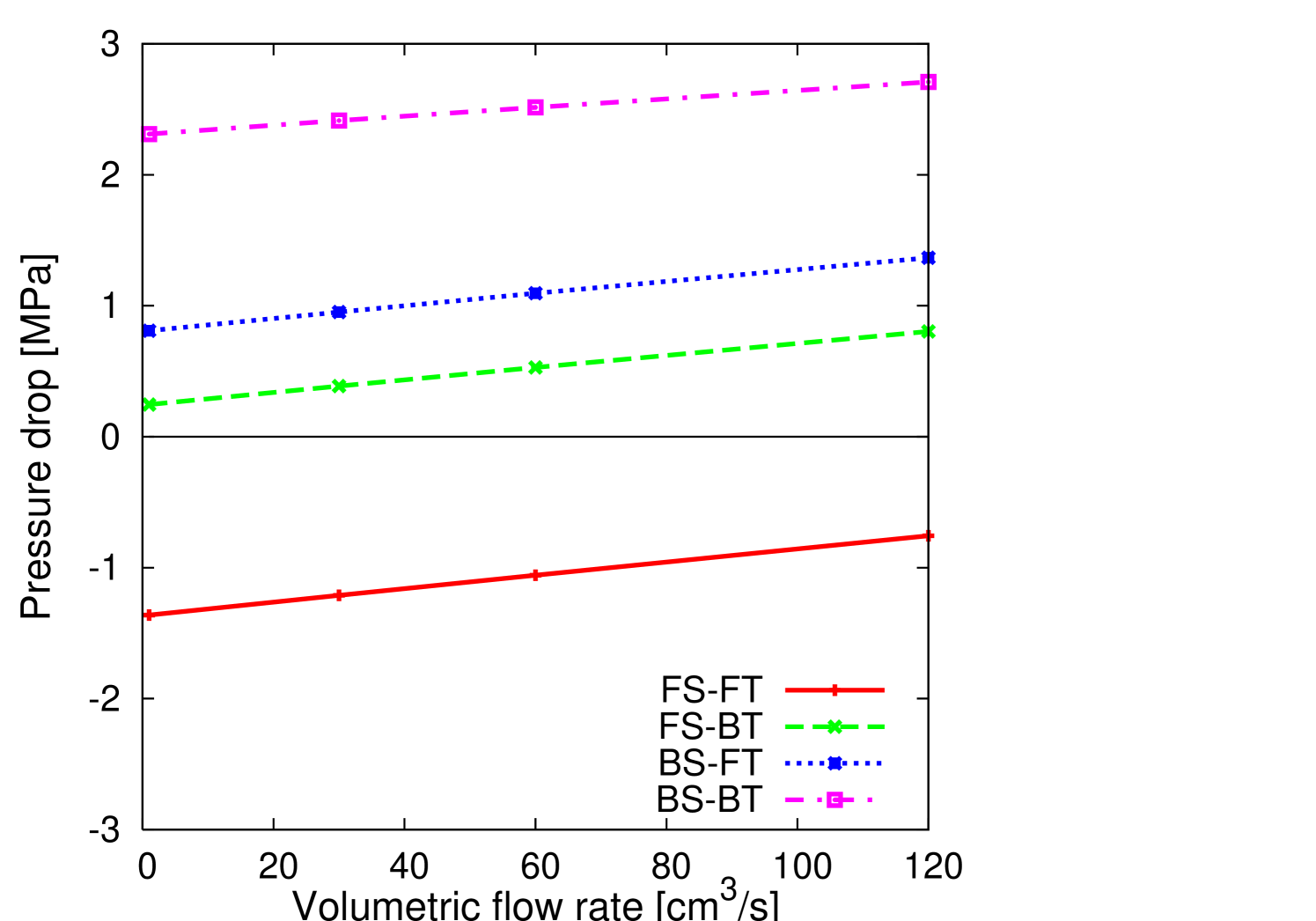
To assess the effect of pitched tips on the pressurization capability, the pressure drop from the inlet to the outlet was calculated under a fixed screw rotation speeds and various volumetric flow rates (Fig.3). For a fixed volumetric flow rate, the pressure drop was largest in Bs-Bt, followed by Bs-Ft, Fs-Bt, and Fs-Ft. The results in Fig.3 show that the disk stagger mainly controls the drag ability of ptKD and that the pitched tips only experience slight modification. It is noted that the pressure drop in Fs-Ft ptKD was negative for a certain range of the volumetric flow rate, which indicates that the pressure-driven flow on average occurred in the direction from the outlet to the inlet.
4.1.2 Temperature profile

Figure 4 shows the average temperature profile along the extrusion direction. For all types of ptKDs, the temperature rose from the inlet temperature to the barrel temperature over one block. Next, the average melt temperature increased two or three degrees beyond the barrel temperature due to viscous heating effects. Because the difference in the results with different types of ptKD was very small, we assume that the temperature did not have a significant effect on the mixing ability.
4.1.3 Residence time and Lagrangian history of exerted stress
Figures 5 and 6 show the joint probability density function (PDF) of the residence time and the Lagrangian-history average of stress magnitude under cm3/s and 200 rpm. To measure the stress magnitude, a second-order invariant of is considered 333 Note that although one of the authors (T.K.) defined “characteristics shear stress” as (Kajiwara et al., 1996) which was used in Yoshinaga et al. (2000) and Ishikawa et al. (2001, 2002), it is not an invariant of a second-rank tensor; therefore, it is not adequate to quantify the magnitude of the stress tensor.. Although is traceless by the incompressibility condition (1), a small but finite is unavoidable in numerical simulations with finite arithmetic. Therefore, we use the traceless part of to compute the stress magnitude, , as
| (10) | ||||
| (11) |
where is the unit tensor.
Counter-pump combinations: Fs-Bt and Bs-Ft
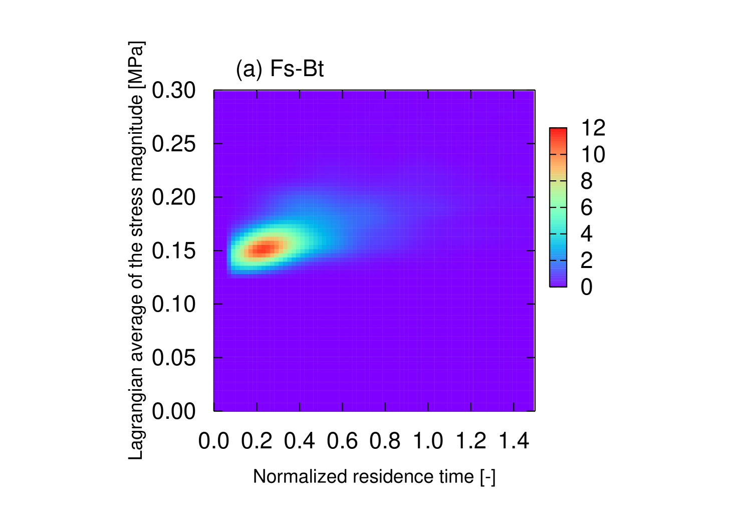
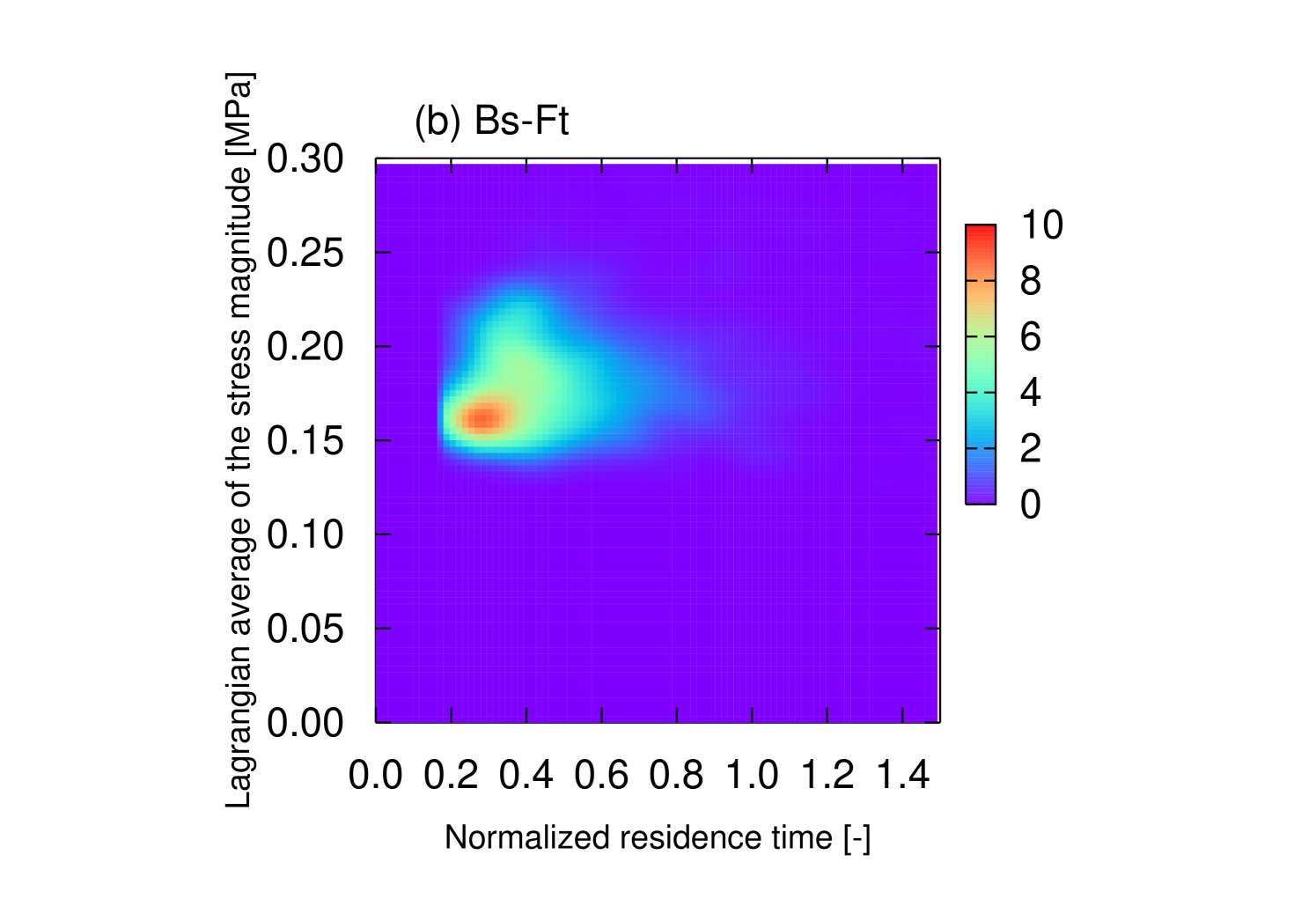
In Fs-Bt and Bs-Ft, the pitched-tip angle and disk-stagger angle are in opposite directions, which we call the counter-pump combination. In the counter-pump combination, the joint PDFs of and are almost unimodal (Fig.5). These ptKDs are characterized by a broad residence time distribution and a rather small fluctuation of . A small fluctuation of indicates that the average stress history of each trajectory is almost homogeneous; thus, homogeneous dispersive mixing can be expected for Fs-Bt and Bs-Ft.
Co-pump combinations: Fs-Ft and Bs-Bt
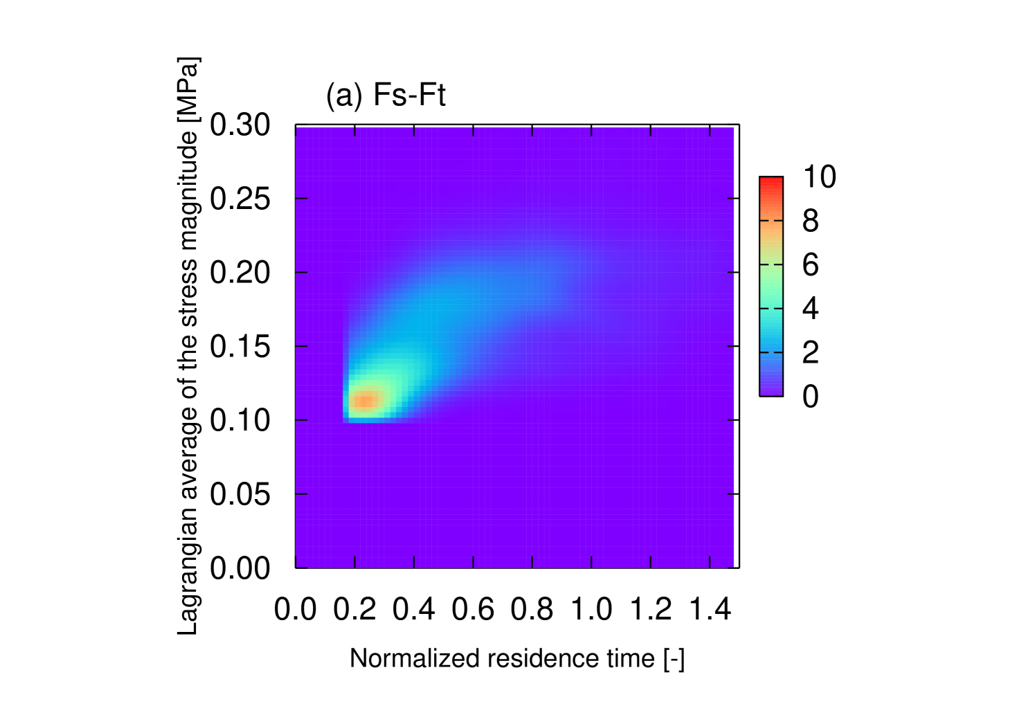
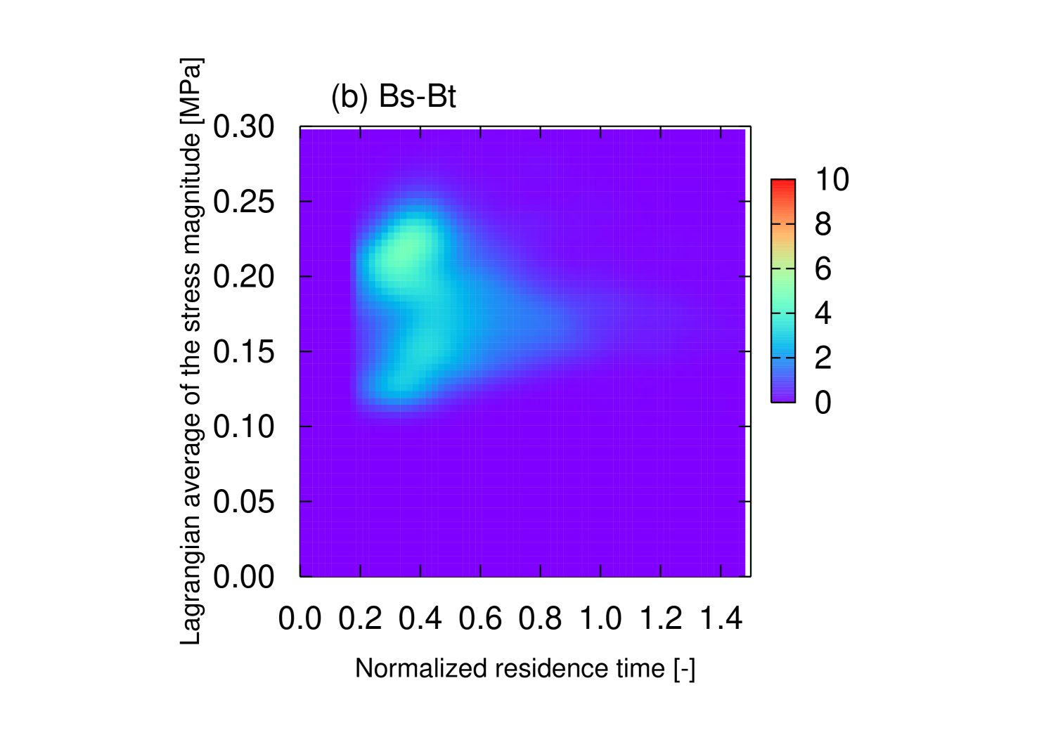
In Fs-Ft and Bs-Bt, the pitched-tip angle and disk-stagger angle are in the same direction, which we call the co-pump combination. In the co-pump combination, the joint PDFs of and are spread over the plane (Fig.6), which indicates that the residence time and stress history of each tracer are highly inhomogeneous.
For the Fs-Ft (Fig.6(a)), the main peak indicates that large population of the tracer has a shorter residence time and smaller average stress, which indicate that pipeline flow occurs where tracers extrude under fast velocity and a small strain-rate and mixing with surrounding fluid rarely occur. The other trajectories have larger average stress during longer residence time.
For the Bs-Bt (Fig.6(b)), the joint PDF of and is bimodal; although, the residence time fluctuation is smaller than those of other ptKDs. The Lagrangian-history average of the stress magnitude has much greater fluctuation than other ptKDs. The bimodal structure indicates that pipeline flow also occurs in Bs-Bt, but the group velocities of the pipeline and its surroundings are similar. Note that the indication of the pipeline flow cannot be observed based only on the residence time distribution. The joint PDF reveals the highly inhomogeneous tracer history in the co-pump combination.
4.2 Transport mechanism and characterization of mixing capability
4.2.1 Time evolution of tracer density
Spatial density of the tracer as a function of time, , is computed from the trajectories of the tracers, . To investigate the axial tracer kinetics, the tracer density is projected in the axial (-) direction as
| (12) | ||||
| (13) |
Figure 4.2.1 shows the evolution of the axial distribution for the four ptKDs, provides detailed information on the transport mechanism, and explains the stress-residence-time joint PDF in the previous section.
RTD has been discussed often in connection with the axial
mixing (Ishikawa et al., 2002; Zhang et al., 2009). However,
a detailed investigation of the axial transport for ptKDs revealed that
the source of the residence time fluctuation differs among the four
types of ptKDs, and that broadness of RTD does not necessarily means
good mixing capability.
![[Uncaptioned image]](https://cdn.awesomepapers.org/papers/124034f9-c98d-4793-943d-b71ff897077a/x12.png)
![[Uncaptioned image]](https://cdn.awesomepapers.org/papers/124034f9-c98d-4793-943d-b71ff897077a/x13.png)
![[Uncaptioned image]](https://cdn.awesomepapers.org/papers/124034f9-c98d-4793-943d-b71ff897077a/x14.png)
![[Uncaptioned image]](https://cdn.awesomepapers.org/papers/124034f9-c98d-4793-943d-b71ff897077a/x15.png) Figure 7: Time evolution of the tracer density on the axial direction for
(a) Fs-Bt,
(b) Fs-Ft,
(c) Bs-Ft, and
(d) Bs-Bt.
The initial axial position of the tracer is depicted by the vertical line on
the second disk.
The different times correspond to the different lines indicated in the legend.
Figure 7: Time evolution of the tracer density on the axial direction for
(a) Fs-Bt,
(b) Fs-Ft,
(c) Bs-Ft, and
(d) Bs-Bt.
The initial axial position of the tracer is depicted by the vertical line on
the second disk.
The different times correspond to the different lines indicated in the legend.
Counter-pump combinations: Fs-Bt and Bs-Ft
For the counter-pump combination, the inter-disk leakage flow in front of the pitched-tips enhanced the axial mixing. As for Fs-Bt in Fig.4.2.1(a), a portion of the tracer was pumped backward at the inter-disk gap. A close investigation of each tracer’s trajectory revealed that the compression flow in front of the backward tips caused this inter-disk backward pump and enhanced the axial mixing. The effect of backward pitched-tips and circumferential mixing at the intermeshing region promoted gross mixing over a whole channel of melt-mixing zone.
As for Bs-Ft in Fig.4.2.1(c), a portion of the tracer was pumped forward at the inter-disk gap by the forward pitched-tips. This effect also caused axial mixing as in the case of Fs-Bt. The broad RTDs observed in Fig.5 are the result of axial mixing, and the unimodal stress-history is a result of gross mixing.
Co-pump combinations: Fs-Ft and Bs-Bt
For Fs-Ft in Fig.4.2.1(b), it is observed that the unimodal axial density immediately split into a bimodal density. These two groups evolved with different axial group velocities. A close investigation of each tracer’s trajectory revealed that the faster axial transport occurred at the roots of the kneading disks where it existed larger space to enhance the pressure-driven flow. The faster group had a pipeline flow characteristic in which mixing with surrounding fluid rarely occurred. Because the forward-pump ability of Fs-Ft ptKD is large, a negative pressure drop is generated in the volumetric flow rate (Fig.3). The gross axial transport is a result of the competing drag and pressure gradient. The broader RTD in Fs-Ft (Fig.6(a)) is a result of pipeline flow and the surroundings. Because the history of exerted stress was different between the pipeline region and the surroundings, fluctuated significantly, as observed in Fig.6(a).
As for Bs-Bt in Fig.4.2.1(d), splitting of the axial density was also observed as in Fs-Ft, but the group axial velocities were closer. A close investigation of each tracer’s trajectory revealed that one group had a character of pipeline flow as in Fs-Ft. The large fluctuation of ( Fig.6(b)) was a result of pipeline flow and the surroundings. However, similar axial group velocities for the pipeline and its surroundings resulted in a narrower RTD (Fig.6(b)).
4.2.2 Mixing capability: strain-rate type and maximum line-stretching rate
For effective mixing, two points that are close initially must separate rapidly over time to promote points distribution in space, stretch a line element, and stretch an area element. To quantify the mixing capability, we considered two aspects of this kinetic process: the potential line-stretching capability and the type of strain-rate field in which the line-stretching occurs.

To quantify the potential line-stretching capability, we used the maximum line-stretching rate
| (14) |
The details of the quantity are described in A. The statistical distribution of the Lagrangian-history average of the maximum line-stretching rate, , is depicted in Fig.8 For co-pump ptKDs, namely Fs-Ft and Bs-Bt, PDFs of are broad. In particular, for Fs-Ft, a shoulder at large is observed. The large fluctuation of is a result of the pipeline flow. In the trajectory by the pipeline flow, is small, and the larger comes from the surroundings. The large fluctuation of indicates that gross mixing might be inhomogeneous in co-pump ptKDs. It is noted that the fingerprint of the pipeline flow is clearer in the PDF of the maximum line-stretching rate than in that of the residence time.
For counter-pump ptKDs, namely Fs-Bt and Bs-Ft, PDFs of are unimodal, which indicates that no special structure exists in the flow pattern in counter-pump ptKDs, and mixing over whole channel is expected.
It is noted that the mean values of indicated in Fig.8 are determined by the disk-stagger direction and are useless for characterizing the mixing capability. To characterize the mixing capability, the fluctuation of should be taken into account.

To identify a type of strain-rate field, the strain-rate-type identifier as a function of the invariants of the strain rate, , is introduced as
| (15) |
where is a unit vector. The strain-rate-type identifier takes values specific to the strain-rate state in incompressible flow,
| (16) |
The details of the strain-rate-type identifier are summarized in A.
The statistical distribution of the Lagrangian-history average of the strain-rate-type identifier, , is depicted in Fig.15. The modes of the PDFs for the four ptKDs are located near , which is a general characteristic of screw extruders in which the contribution from circumferential shear flow is almost . A close look at the modes in the inset of Fig. 9 reveals that the ptKD characteristics were found. For co-pump ptKDs, namely Fs-Ft and Bs-Bt, the modes of their PDFs indicate that the history of the strain-rate type is planar shear flow. In contrast, for counter-pump ptKDs, namely Fs-Bt and Bs-Ft, the contribution of biaxial elongational flow at the pitched tips causes mode to shift to a lower value of . The result suggests that the counter-pump ptKDs to generate the three-dimensional deformation, which promotes efficient mixing, are more effectively than co-pump ptKDs.
5 Concluding remarks
For melt-mixing with a novel mixing element, the “pitched-tip kneading disk (ptKD)”, its basic characteristics and mixing capability were investigated based on numerical simulation of three-dimensional flow and the statistics of the Lagrangian tracer. The ptKD has two main geometric parameters: the pitched-tip angle and the disk-stagger angle. Four typical combinations of the pitched-tip angle and disk-stagger angle were used in the current research.
The pressurization capability is mainly determined by the disk-stagger angle, and the pitched-tip provides minor modification.
Flow patterns and transport mechanisms were studied according to the tracer density evolution. In co-pump ptKDs (Fs-Ft and Bs-Bt), pipeline flow exists that causes a large fluctuation in the Lagrangian history of several quantities, including the exerted stress and the line-stretching rate. In co-pump ptKDs, the pitched-tip enhances the pressurization and causes the axial transport to be inhomogeneous by generating pipeline flow.
In counter-pump ptKDs (Fs-Bt and Bs-Ft), the biaxial elongational flow occurs in front of the pitched-tip and enhances mixing over the channel. The result suggests that the main advantage of Fs-Bt and Bs-Ft is gross distributive mixing. It is expected that, the optimal balance of distributive mixing and dispersive mixing are found for various extrusion processes by adjusting the combinations of the pitched-tip angle and the disk-stagger angle in Fs-Bt and Bs-Ft.
To quantify of mixing capability, the maximum line-stretching rate and the strain-rate-type identifier were introduced. Information on the flow patterns and mixing capability is reflected in the statistics of Lagrangian-history averages of the maximum line-stretching rate and the strain-rate-type identifier. These quantities are useful for analyzing the results of three-dimensional flow simulations.
Other characterizations of mixing in three-dimensional flow using the Lyapunov exponent (Lawal and Kalyon, 1995a) and intensity of segregation (Lawal and Kalyon, 1995b) have been suggested. It would be interesting to compute these measures in ptKDs and to compare the results with those of other kneading elements. We are currently working on this project.
Acknowledgments
The computation was partly carried out using the computer facilities at the Research Institute for Information Technology in Kyushu University and the Supercomputing Division of Information Technology Center at the University of Tokyo.
Appendix A Local line-stretching rate and type of strain-rate field
The mixing ability of a flow field can be quantified by the line-stretching rate of an infinitesimally short line element . The time evolution of obeys for a short time period
| (17) |
The stretching rate of the norm is derived from Eq.(17) as
| (18) |
When the line-stretching rate is positive, an infinitesimally small distance nearby two points separate in exponential manner.
The stretching rate of (18) depends on the direction of . To characterize the mixing ability of a given flow field, the maximum of Eq.(18) or equivalently the maximum line-stretching rate, in Eq.(14) can be used. By definition, coincides with the largest eigenvalue of .
In the theory of dynamical systems in a bounded system, the average stretching rate based on the director advected by Eq.(17) on the limiting trajectory is called the Lyapunov exponent, and a positive Lyapunov exponent indicates that the dynamical system is chaotic (Ott, 2002). The Lagrangian-history average of is different from the Lyapunov exponent in the choice of the director, but can be used to characterize potential ability of line stretching by the flow. From the viewpoint of distributive mixing, the magnitude of and its distribution in time and space can be used to characterize the mixing ability.
While the line-stretching rate characterizes the stretching in one direction, the strain rate tensor describes the tri-axial straining states. By using the maximum line-stretching rate and , the types of flow, namely the planar shear flow, uniaxial flow and biaxial elongational flows, are identified. The ratio of the maximum line-stretching rate to the second moment of is introduced in Eq.(15). It is noted that coincides with the mixing efficiency (Ottino, 1989) except for the choice of the direction . By definition, is an invariant of . For incompressible flow, is expressed by its largest and smallest eigenvalues, and ,
| (19) |
therefore is found to be a function of as
| (20) |
The incompressibility condition indicates that , , and the range of . Thus is increasing monotonically on and lies in
| (21) |
For uniaxial and biaxial elongational flows, and , respectively. For planar shear flow, . The corresponding is summarized in Eq.(16).
Because the uniaxial elongational flow establishes a more effective flow pattern in dispersive mixing than simple shear flow, several authors (Yang and Manas-Zloczower, 1992; Yao and Manas-Zloczower, 1998; Cheng and Manas-Zloczower, 1997; Cheng and Manas-Zloczower, 1998) have utilized some indicator of the strain pattern based on and like
| (22) | ||||
| (23) |
where is the vorticity tensor and indicates the steady co-rotational time derivative. Both and takes certain values for elongational flow, simple shear flow, and simple rotational flow. The flows can be discriminated based on the ratio of the a magnitude of vorticity to a magnitude of which indirectly identifies the strain pattern: null vorticity, , in pure elongational flow, and in simple shear flow. By definition, and cannot distinguish between uniaxial and biaxial elongational flows. Like and , can be used to identify a type of strain-rate. It is noted that is different from and in that is based solely on the strain rate and provides a direct characterization of because we are interested in the stretching rate of the distance of two nearby points and the rotational component of flow does not affect the maximum line-stretching rate.
References
- Alsteens et al. (2004) Alsteens, B., Legat, V., Avalosse, T., 2004. Parametric study of the mixing efficiency in a kneading block section of a twin-screw extruder. Int. Polym. Process. 19, 207–217.
- Booy (1978) Booy, M. L., 1978. Geometry of fully wiped twin-screw equipment. Polym. Eng. Sci. 18, 973–984.
- Bravo et al. (2000) Bravo, V. L., Hrymak, A. N., Wright, J. D., 2000. Numerical simulation of pressure and velocity profiles in kneading elements of a co-rotating twin screw extruder. Polym. Eng. Sci. 40 (2), 525–541.
- Bravo et al. (2004) Bravo, V. L., Hrymak, A. N., Wright, J. D., 2004. Study of particle trajectories, residence times and flow behavior in kneading discs of intermeshing co-rotating twin-screw extruders. Polym. Eng. Sci. 44 (4), 779–793.
- Brooks and Hughes (1982) Brooks, A., Hughes, T., 1982. Streamline upwind/petrov-galerkin formulations for convection dominated flows with particular emphasis on the incompressible navier-stokes equations. Comput. Methods Appl. Mech. Engrg. 32, 199–259.
- Cheng and Manas-Zloczower (1997) Cheng, H., Manas-Zloczower, I., 1997. Study of mixing efficiency in kneading discs of co-rotating twin-screw extruders. Polym. Eng. Sci. 37 (6), 1082–1090.
- Cheng and Manas-Zloczower (1998) Cheng, H., Manas-Zloczower, I., 1998. Distributive mixing in conveying elements of a zsk-53 co-rotating twin screw extruder. Polym. Eng. Sci. 38 (6), 926–935.
- Funatsu et al. (2002) Funatsu, K., Kihara, S.-I., Miyazaki, M., Katsuki, S., Kajiwara, T., 2002. 3-d numerical analysis on the mixing performance for assemblies with filled zone of right-handed and left-handed double-flighted screws and kneading blocks in twin-screw extruders. Polym. Eng. Sci. 42 (4), 707–723.
- Ishikawa et al. (2002) Ishikawa, T., Amano, T., Kihara, S.-I., Funatsu, K., 2002. Flow patterns and mixing mechanisms in the screw mixing element of a co-rotating twin-screw extruder. Polymer Engineering & Science 42 (5), 925–939.
- Ishikawa et al. (2000a) Ishikawa, T., Kihara, S.-I., Funatsu, K., 2000a. 3-d numerical simulations of nonisothermal flow in co-rotating twin screw extruders. Polym. Eng. Sci. 40 (2), 357–364.
- Ishikawa et al. (2001) Ishikawa, T., Kihara, S.-i., Funatsu, K., 2001. 3-d non-isothermal flow field analysis and mixing performance evaluation of kneading blocks in a co-rotating twin srew extruder. Polym. Eng. Sci. 41 (5), 840–849.
- Ishikawa et al. (2000b) Ishikawa, T., Kihara, S.-I., Funatsu, K., Amaiwa, T., Yano, K., 2000b. Numerical simulation and experimental verification of nonisothermal flow in counter-rotating nonintermeshing continuous mixers. Polym. Eng. Sci. 40 (2), 365–375.
- Jaffer et al. (2000) Jaffer, S. A., Bravo, V. L., Wood, P. E., Hrymak, A. N., Wright, J. D., 2000. Experimental validation of numerical simulations of the kneading disc section in a twin screw extruder. Polymer Engineering & Science 40 (4), 892–901.
- Kajiwara et al. (1996) Kajiwara, T., Nagashima, Y., Nakano, Y., Funatsu, K., 1996. Numerical study of twin-screw extruders by three-dimensional flow analysis - development of analysis technique and evaluation of mixing performance for full flight screws. Polym. Eng. Sci. 36 (16), 2142–2152.
- Kalyon and Malik (2007) Kalyon, D. M., Malik, M., 2007. An integrated approach for numerical analysis of coupled flow and heat transfer in co-rotating twin screw extruders. Int. Polym. Process. 22 (3), 293–302.
- Lawal and Kalyon (1995a) Lawal, A., Kalyon, D. M., 1995a. Mechanisms of mixing in single and co-rotating twin screw extruders. Polym. Eng. Sci. 35 (17), 1325–1338.
- Lawal and Kalyon (1995b) Lawal, A., Kalyon, D. M., 1995b. Simulation of intensity of segregation distributions using three-dimensional fem analysis: Application to corotating twin screw extrusion processing. J. Appl. Polym. Sci. 58 (9), 1501–1507.
- Levenspiel (1998) Levenspiel, O., 1998. Chemical Reaction Engineering, 3rd Edition, 3rd Edition. Wiley, New York.
- Malik and Kalyon (2005) Malik, M., Kalyon, D. M., 2005. 3d finite element simulation of processing of generalized newtonian fluids in counter-rotating and tangential tse and die combination. Int. Polym. Process. 20 (4), 398–409.
- Marchal and Crochet (1987) Marchal, J. M., Crochet, M. J., 1987. A new mixed finite element for calculating viscoelastic flow. Journal of Non-Newtonian Fluid Mechanics 26, 77–114.
- Ott (2002) Ott, E., 2002. Chaos in Dynamical Systems, 2nd Edition. Cambridge University Press, Cambridge, UK.
- Ottino (1989) Ottino, J. M., 1989. The Kinematics of Mixing: Stretching, Chaos, and Transport (Cambridge Texts in Applied Mathematics). Cambridge University Press, Cambridge, UK.
- Shigeishi et al. (2006) Shigeishi, T., Saga, D., Tomiyama, H., Fukushima, T., Ishibashi, M., Inoue, S., July 2006. Development of special kneading screw in twin screw extruder. In: Proceedings of 22nd Annual Meeting of the Polymer Processing Society. pp. G04–12.
- Yang and Manas-Zloczower (1992) Yang, H.-H., Manas-Zloczower, I., 1992. Flow field analysis of the kneading disc region in a co-rotating twin screw extruder. Polym. Eng. Sci. 32 (19), 1411–1417.
- Yao and Manas-Zloczower (1998) Yao, C.-H., Manas-Zloczower, I., 1998. Influence of design on dispersive mixing performance in an axial discharge continuous mixer - lcmax 40. Polym. Eng. Sci. 38 (6), 936–946.
- Yoshinaga et al. (2000) Yoshinaga, M., Katsuki, S., Miyazaki, M., Liu, L., Kihara, S.-I., Funatsu, K., 2000. Mixing mechanism of three-tip kneading block in twin screw extruders. Polym. Eng. Sci. 40 (1), 168–178.
- Zhang et al. (2009) Zhang, X.-M., Feng, L.-F., Chen, W.-X., Hu, G.-H., 2009. Numerical simulation and experimental validation of mixing performance of kneading discs in a twin screw extruder. Polym. Eng. Sci. 49 (9), 1772–1783.
- Zienkiewicz (1977) Zienkiewicz, O. C., June 1977. The Finite Element Method, 3rd Edition. McGraw Hill Higher Education, UK.