Open Cell Metal Foams for Beam Liners ?
Abstract
The possible use of open-cell metal foams for particle accelerator beam liners is considered. Available materials and modeling tools are reviewed, potential pros and cons are pointed out, and a study program is outlined.
1 INTRODUCTION
Molecular gas desorption from the beam-pipe wall
due to synchrotron radiation
should be properly taken into account
in the design of high energy particle accelerators and storage rings.
This is specially true for hadron colliders, where nuclear scattering in the
residual gas, besides limiting the beam luminositity lifetime, may produce
high energy protons causing thermal runaway and quenching
of superconducting magnets.
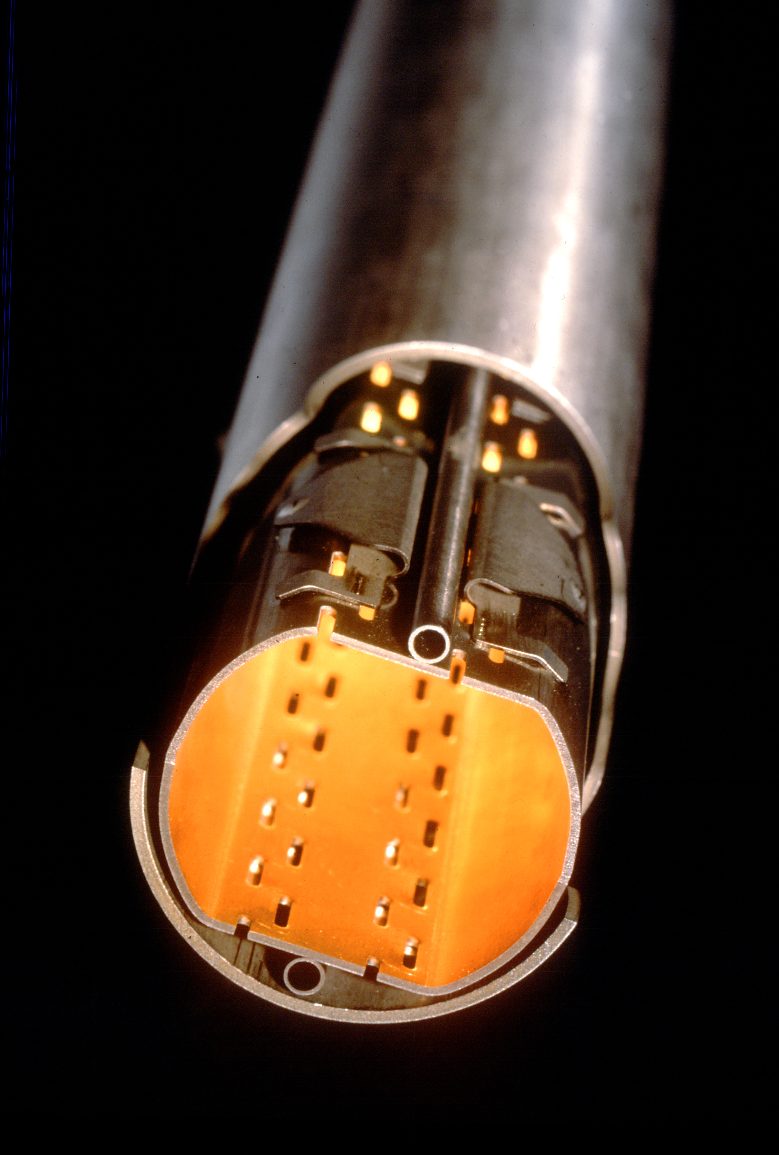
In the CERN Large Hadron Collider [1] a copper-coated stainless-steel beam pipe (or liner)
is kept at by active Helium cooling, and effectively handles
the heat load represented by synchrotron radiation,
photoelectrons, and image-charge losses.
A large number ( ) of tiny slots are drilled in the liner wall (see Figure 1)
in order to maintain the desorbed gas densities below a critical level
( for )
by allowing desorbed gas to be continuously cryopumped toward the
stainless steel cold bore (co-axial to the liner) of the superconducting magnets,
which is kept at by superfluid Helium.
The size, geometry and density of the pumping holes
affect the beam dynamics and stability in a way which is
synthetically described by the longitudinal and transverse
beam coupling impedances [2].
The hole geometry should be chosen so as to minimize
the effect of trapped (cut-off) modes,
and the hole pattern should be designed so as to prevent
the possible coherent buildup of synchrotron radiation
in the TEM waveguide limited by the pipe and the cold bore [3].
Open-cell metal foams could be interesting candidate materials
for beam liner design.
In the following we give a brief review of their properties, and of the pertinent modeling tools,
and draw some preliminary conclusions about the pros and cons of their possible use
in beam liners.
2 OPEN-CELL METAL FOAMS
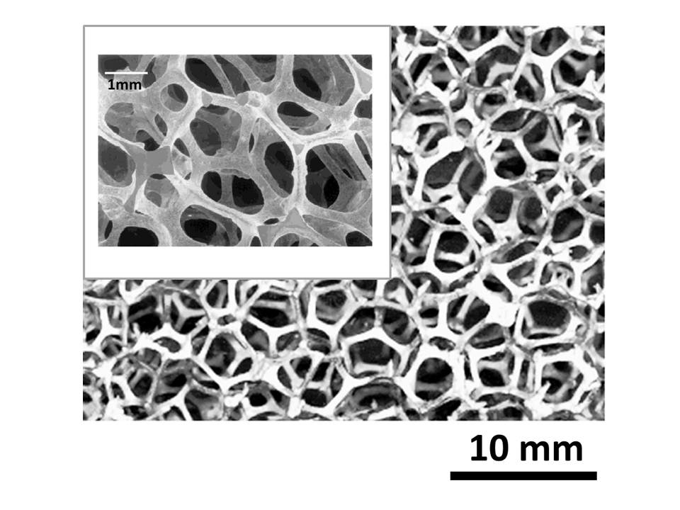
Open-cell metal foams are produced either by vapor- (or electro-) deposition of metal on an open-cell polymer template, followed by polymer burn-off, and a final sintering step to densify the ligaments. Alternatively, they are obtained by infiltration/casting of molten metal into a solid mould, consisting of packed (non-permeable) templates of the pores, followed by burn-out and removal of the mould [4]. Both processes result into highly gas-permeable reticulated foams, where only a 3D web of solid conducting struts among the pores survives. The typical structure of these materials is displayed in Figure 2.
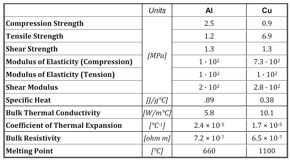
The key structural parameters of reticulated metal foams are the vacuum ”pore” size, and the porosity (volume fraction of pores). Pore sizes in the range from to and porosities in the range 0.8 - 0.99 are currently manufactured. These two parameters determine the material’s gas-permeability, and, together with the electrical properties of the metal matrix, its electrical properties. Metal foams have interesting structural properties (low density and weight, high (tensile and shear)-strength/weight ratio, nearly isotropic load response, low coefficient of thermal expansion), as summarized in Table I, which qualified them among the most interesting new materials for aerospace applications.
Aluminum and Copper open-cell foams are presently available off-the-shelf [5],
and are relatively cheap.
They can be further coated, e.g., with Silver, Titanium or Platinum,
for special purpose applications.
Foams using Steel or Brass, as well as pure Silver, Nickel, Cobalt, Rhodium, Titanium or Beryllium have been
also produced by a number of Manufacturers.
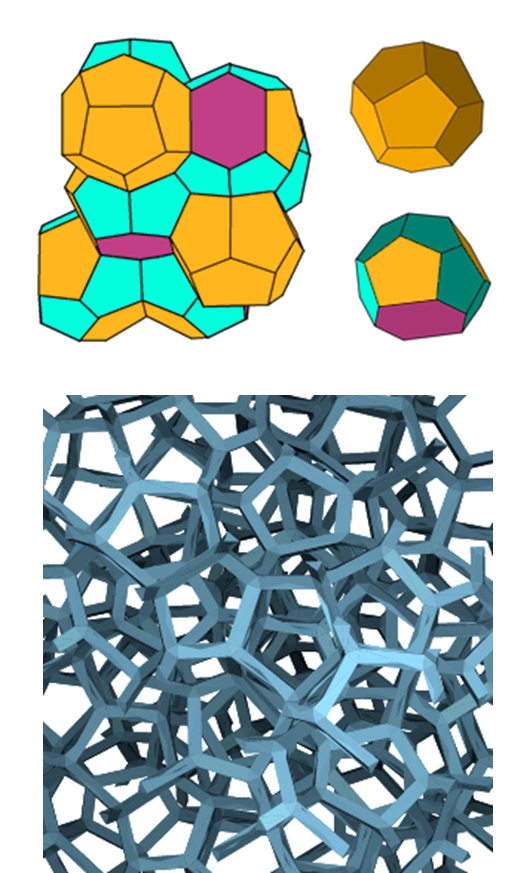
The Weaire-Phelan (WP) space-filling honeycombs are credited
to provide the natural
(i.e., Plateau’s minimal surface principle compliant)
model of a reticulated metal with equal-sized
(but possibly unequal-shaped) pores [6].
The WP unit cell consists of a certain arrangement of (irregular)
polyhedra, namely two pentagonal-face dodecahedra (with tetrahedral symmetry ) ,
and six tetrakaidecahedra (with antiprysmatic symmetry ) featuring
two hexagonal and twelve pentagonal faces.
A computer generated WP honeycomb is displayed in Figure 4, and
its visual similarity to Figure 2 is apparent.
2.1 Electrical Properties of Metallic Foams
Full electromagnetic modeling of reticulated metal foams is still to come.
A numerical approach based on Weiland’s finite integration technique
(FIT, [7]) has been proposed by Zhang et al. [8] to compute
the (frequency, thickness and angle of incidence dependent) reflection coefficient
of SiC reticulated foam, and optimize its design.
A simplified model, consisting of stacked square-mesh grids has been used
by Losito et al. [9],[10] to investigate the RF shielding properties
of metallic foams.
The main limitation of Zhang’s analysis is in the use of a simple body-centered-cubic
unit-cell foam model, for easiest numerical implementation.
The FIT scheme, however may accommodate in principle more complicated and realistic
foam-cell geometries, including in principle the WP one.
In the limit where bubbles and metal struts are much smaller than the smallest
wavelength of interest, the DC conductivity of a metal foam can be computed using effective medium theory
(EMT), for which several formulations exist (see, e.g., [11]-[13] for a review).
These include:
i) the “infinite dilution” approximation, where inclusions do not interact,
and are subject to the field which would exist in the homogeneous host;
ii) the self-consistent approach [14], credited to Bruggemann,
where inclusions are thought of as being embedded in the (yet to be modeled) effective medium;
iii) the differential scheme, whereby inhomogeneities are incrementally added to the composite111
In this approach, the total concentration of inhomogeneities does not coincide with the volume fraction ,
because at each step new inclusions may be placed where old inclusions have already been set.,
until the final concentration is reached, so that at each step the inclusions do not interact,
and do not modify the field computed at the previous step [15];
iv) the effective-field methods, whereby interaction among the inclusions is described in terms of an effective field
acting on each particle, accounting for the presence of the others.
Two main versions of this method exist, credited to Mori-Tanaka [16] and Levin-Kanaun [17],
differing in the way the effective field is computed
(average over the matrix only, or average over the matrix and the inclusions, respectively).
Both the infinite-dilution and the self-consistent approaches yield
| (1) |
where is the bulk metal conductivity, is the porosity (volume fraction of the vacuum bubbles). and is a morphology-dependent factor. The differential approach yields
| (2) |
while the Mori-Tanaka/Levin-Kanaun approaches yield
| (3) |
All equations (1)-(3) merge, as expected, in the limit. The various models are synthetically compared in Figure 5.
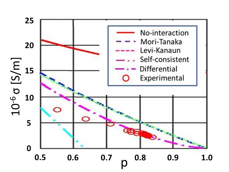
All these models predict larger conductivity then observed in measurements on Al foams222
It should be noted that open and closed cell metal foams behave similarly in terms of electrical conductivity,
while being markedly different as regards thermal conductivity, due to the different role of convective flow..
This has been attributed to significant oxide formation on the Al conducting web [18].
Equation (2) agrees in form with predictions
based on percolation theory [19] - although strictly speaking
there’s no threshold here beyond which the conducting component disconnects.
3 METAL FOAMS vs SOLID METAL
PERFORATED WALLS
In this section we shall attempt to draw a comparison between a metal-foam beam-pipe wall and a solid-metal perforated one, in terms of the relevant vacuum and beam-coupling impedance features .
3.1 Vacuum Issues
The vacuum dynamics for each molecular species which may be desorbed from the wall by synchrotron radiation can be described by the following set of (coupled) rate equations [20]
| (4) |
Here and are the
volume and surface densities of desorbed particles, respectively,
and and represent the volume and wall-area of the liner
per unit length, respectively.
The first term on the r.h.s. of the first rate equation represents the
number of molecules desorbed by synchrotron radiation per unit length
and time, and is given by
| (5) |
where is the desorption yield (number of desorbed molecules per incident photon) and is the specific photon flux (number of photons hitting the wall per unit length and time). The second term represents the number of molecules which are removed per unit time and unit length by either sticking to the wall, or escaping through the holes. The coefficient in (4) can be accordingly written
| (6) |
where is the average molecular speed, being the molecular mass, the Boltzmann constant ant the absolute temperature, is the average numer of collisions of a single molecule per unit time and unit wall surface, is the sticking probability, and is the escape probability. The third term accounts for thermal or radiation induced re-cycling of molecules sticking at the walls. The coefficient in (4) can be accordingly written
| (7) |
Here the first term accounts for radiation induced recycling,
described by the coefficient ,
while the second term describes thermally-activated recycling,
being a typical molecular vibrational frequency,
and a typical activation energy.
The term appears
with reversed sign on the r.h.s. of the second rate equation,
where it represents the the number of molecules de-sticking from the
wall surface per unit time and unit length.
The first term on the r.h.s. of this equation
represents the number of molecules
sticking to the wall, per unit time and unit length,
whence (compare with eq. (6))
| (8) |
At equilibrium, , and the rate equations yield:
| (9) |
Typical values (from LHC) of the parameters in (9) are collected in Table II below [20].
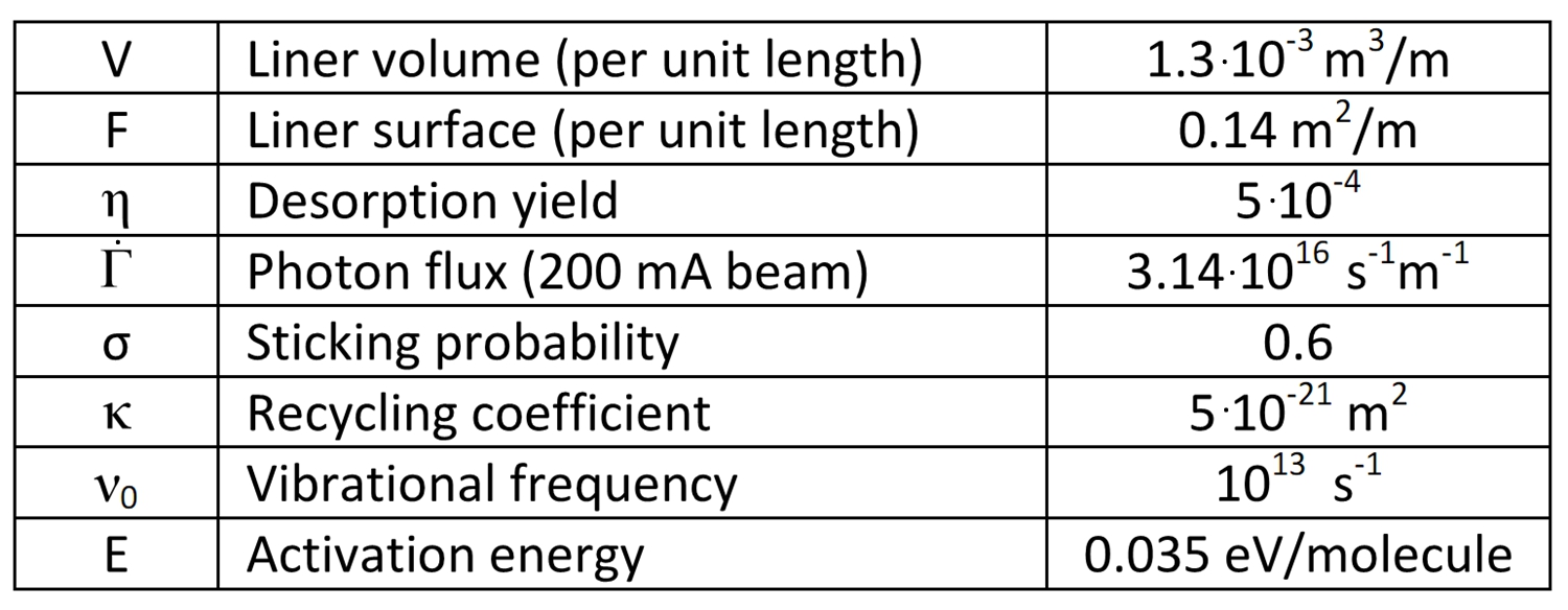
The equilibrium molecular densities in (9) should not exceed some critical values for safe operation [20].
3.1.1 Perforated Solid Metal Wall
For a liner wall with vanishing thickness the escape probability in (6) and (9) will be simply equal to the holey fraction of the wall surface. For holes drilled in a thick wall, the escape probability will be less than , differing from this latter by a factor (named after Clausing) which takes into account the nonzero probability that a molecule may stick at the hole internal surface rather than escaping outside [21]. The Clausing factor for thick cylindrical holes drilled in a metal wall is well approximated by the following empirical formula credited to Iczkowski [22] :
| (10) |
where and are the thickness and radius of the hole.
3.1.2 Open Cell Metal Foam Wall
For an open cell foam the porosity (volume fraction of voids), average pore radius , and volume density of pores are related by:
| (11) |
which allows to compute from and . It is reasonable to assume that the surface density of the holes will be , each hole having an average surface so that the fraction of (unit) surface covered by holes will be
| (12) |
which will exceed for a typical () (volume) porosities.
This is a large number, compared, e.g., to the LHC liner value .
This suggests letting
in eqs. (6) and (9),
since molecules can only stick to the solid portion of the wall surface.
On the other hand, not all molecules hitting the holey portion of the wall
will escape, and we may expect a (much) larger Clausing factor, compared to the simple case
of (right) cylindrical holes drilled in a thick solid plate333
The gas-permeability of metal foams has been investigated since long,
both experimentally [23] and theoretically (see, e.g., [24] for a recent account).
Unfortunately, little attention has been paid so far to the molecular flow limit. .
We may naively assume that the effective number of molecules (per unit time and length)
which will escape from a metal-foam wall with thickness ,
will be related to the number (per unit time and length) of those
entering the face-holes by a Lambert-Beers factor, so that
| (13) |
reflecting the fact that those molecules
may collide with and stick to the (inner) metal web, instead of escaping.
The obvious requirement that (13) agrees with (10)
in the limit yields as an estimate
of the extinction length in (13).
Note that synchrotron radiation will not penetrate the metal foam
beyond a few skin-depths , so that not all molecules sticking to the metal web
inside the metal foam could be recycled by synchrotron radiation.
This implies that the value of the recycling factor in (7) and (9)
may be significantly different for a reticular wall.
3.2 Beam Coupling Impedance
and Parasitic Loss
Beam coupling impedances provide a synthetic description of the beam-pipe interaction, for investigating beam dynamics and stability [2]. For the simplest case of a circular pipe of radius with on-axis beam, the longitudinal beam-coupling impedance per unit length is given by
| (14) |
where is the wall impedance, and a Leontóvich assumption is implied444 Equation (14) is a special case of a general formula which allows to compute the longitudinal and transverse beam-coupling impedances of a pipe with complicated geometric and constitutive properties [25].. Similarly, the nonzero components of the diagonal transverse beam coupling impedance dyadic are
| (15) |
where is the speed of light in vacuum. The parasitic loss (energy lost by the beam per unit pipe length) is directly related to the longitudinal impedance via
| (16) |
where is the beam-current frequency spectrum [2].
The beam coupling impedances (and parasitic losses) should not exceed
some critical values for safe operation [1].
3.2.1 Perforated Solid Metal Wall
The wall impedance for a perfectly conducting perforated beam pipe was deduced in [26] and [27] in the Bethe limit where the hole size is much smaller than the (shortest) wavelength of interest, yielding
| (17) |
| (18) |
where are the electric and magnetic hole polarizabilities, and is the surface density of holes. For circular holes with radius in a wall with thickness one has, e.g.,
| (19) |
where and are the longitudinal damping constants of the dominant TE and TM cutoff mode of a circular waveguide having the same radius as the holes. Equation (18) can be used in (16) to compute the parasitic loss due to the synchrotron radiation leaking through the holes. The parasitic loss due to the finite bulk conductivity of the liner wall, can also be obtained from (16) using
| (20) |
in (14).
3.2.2 Open Cell Metal Foam Wall
The wall impedance of a reticular metal is given by (20),
in terms of the effective conductivity of the material.
Equations (14) and (15) give the corresponding beam coupling impedances,
and equation (16) yields the related parasitic loss.
Heuristically, we can also use the skin depth of the reticular metal (evaluated at the
frequency of the synchrotron radiation )
| (21) |
to set the thickness of the open-cell metal-foam wall, and estimate the fraction of parasitic loss due to synchrotron radiation leakage as
| (22) |
4 CONCLUSIONS
On the basis of the above hints, some preliminary qualitative
conclusions can be drawn about the possible use of reticular metals in
beam liners.
The structural properties of the material may be adequate to resist to eddy-current
induced stresses, in case of superconducting magnets’ failure.
For a given out-gassing capacity, a smaller total surface of reticular metal may be needed,
thanks to the much larger gas permeability of open-cell metal foams in the molecular-flow regime,
compared to perforated solid-metal.
At the same time, synchrotron radiation leakage could be lower, due to better EM shielding properties,
and the risk of coherent beaming of synchrotron radiation in the TEM region between the outer liner wall and
the cold bore would be reduced, due to the almost random hole pattern.
Bulk ohmic losses in reticular metals, on the other hand, may be much larger compared to solid metals.
This could be mitigated to some extent by coating the metallic web, e.g., with a superconducting material.
Using, e.g., relatively larg(er) holes/slots in the beam-liner,
backed by metal foam strips could possibly cope with
the very stringent vacuum and impedance requirements of the perspective SLHC [28].
In order to translate the above hints into quantitative design criteria,
further modeling effort and substantial experimental work are obviously in order.
We believe that such a study program is worth being pursued,
and that the available modeling tools and technologies provide a good starting point for
its succesful implementation.
We are accordingly preparing a research proposal on the subject to be
submitted to the Italian National Institute
for Nuclear Physics Research (INFN).
References
- [1] - ”The Large Hadron Collider Conceptual Design,” CERN Rept. AC/95-05 (1995).
- [2] B.W. Zotter and S.A. Kheifets, ”Impedances and Wakes in High Energy Particle Accelerators,” World Scientific, Singapore (1998).
- [3] S. Heifets and A. Mikhailichenko, ”Coherent Synchrotron Radiation in Multiply Connected Vacuum Chamber,” SLAC Pub. 8428 (2000).
- [4] J. Banhart and N.A. Fleck, ”Cellular Metals and Metal Foaming Technology,” MIT Press, Boston (2003).
- [5] www.ergaerospace.com
- [6] D. Weaire and R. Phelan, ”A Counter-Example to Kelvin’s Conjecture on Minimal Surfaces,” Phil. Mag. Lett. 69 (1994) 107.
- [7] T. Weiland, ”A Discretization Method for the Solution of Maxwell’s Equations for Six-Component Felds,” AEU Int. J. Electr. C31 (1977) 116.
- [8] H. Zhang et al., ”Numerical Predictions for Radar Absorbing Silicon Carbide Foams Using a Fnite Integration Technique with a Perfect Boundary Approximation,” Smart Mater. Struct. 15 (2006) 759.
- [9] O. Losito et al., ”A Wide-Frequency Model of Metal Foam for Shielding Applications,” IEEE Trans. EMC-52 (2010) 75.
- [10] G.Monti, L. Catarinucci and L. Tarricone, ”New materials for electromagnetic shielding: Metal foams with plasma properties,” MOTL 52 (2010) 1700.
- [11] F.G. Cuevas et al., ”Electrical Conductivity and Porosity Relationship in Metal Foams,” J. Porous. Mater. 16 (2008) 675.
- [12] I. Sevostianov, J. Kovacic and F. Simancik, ”Elastic and Electric Properties of Closed Cell Aluminum Foams,” Mat. Sci. Eng. A420 (2006) 87.
- [13] R. Goodall, L. Weber and A. Mortensen, ”The Electrical Conductivity of Microcellular Metals,” J. Appl. Phys., 100 (2006) 044912.
- [14] D.A.G. Bruggemann, ”Berechnung Verschiedener Physikalischer Konstanten von Heterogenen Substanzen,” Ann. Phys. 24 (1935) 636.
- [15] R. McLaughlin, ”A Study of the Differential Scheme for Composite Materials,” Int. J. Eng. Sci. 5 (1977) 237.
- [16] Y. Qui and G.J. Weng, ”On the Application of Mori–Tanaka’s Theory Involving Transversely Isotropic Spheroidal Inclusions,” Int. J. Eng. Sci. 28 (1990) 1121.
- [17] S.K. Kanaun, ”Dielectric Properties of Matrix Composite Materials with High Volume Concentration of Inclusions (Effective Field Approach),” Int. J. Eng. Sci. 41 (2003) 1287.
- [18] T. W. Clyne, ”Thermal and Electrical Conduction in MMCs,” in “Comprehensive Composite Materials,” Elsevier, Amsterdam (2000).
- [19] D. Stauffer and A. Aharony, ”Introduction to percolation Theory,” Taylor and Francis, London (1992).
- [20] O. Gröbner, ”Overview of the LHC Vacuum System,” Vacuum 60 (2001) 25.
- [21] W. Steckelmacher, ”Knudsen Flow 75 Years on: the Current State of the Art for Flow of Rarefied Gases in Tubes and Systems,” Rep. Progr. Phys. 49 (1986) 1083.
- [22] R.P. Iczkowski, J.L. Margrave and S.M. Robinson, ”Effusion of Gases through Conical Orifices,” J. Phys. Chem. 67 (1963) 229.
- [23] B.R.F. Kendall, ”Vacuum Applications of Metal Foams,” J. Vac. Sci. Technol. 17 (1980) 1385.
- [24] K. Boomsma, D. Poulikakos and Y. Ventikos, ”Simulation of Flow through Open Cell metal Foams using an Idealized Periodic Cell Structure,” Int. J. Heat and Fluid Flow 24 (2003) 825.
- [25] S. Petracca, ”Reciprocity Theorem for Coupling Impedance Computation in the LHC Liner.,” Part. Acc. 50 (1995) 211.
- [26] S.S. Kurrenoy, ”Couling Impedances of Pumping Holes,” Particle Accel. 39 (1992) 1.
- [27] S. Petracca, ”Beam Coupling Impedances for Perforated Beam Pipes with General Shape from Impedance Boundary Conditions,” Phys. Rev. E60 (1999) 6030.
- [28] http://care-hhh.web.cern.ch/CARE-HHH/LUMI-06/