Parametrically driven pure-Kerr temporal solitons in a chip-integrated microcavity
Abstract
The discovery that externally-driven nonlinear optical resonators can sustain ultrashort pulses corresponding to coherent optical frequency combs has enabled landmark advances in applications from telecommunications to sensing. The main research focus has hitherto been on resonators with purely cubic (Kerr-type) nonlinearity that are externally-driven with a monochromatic continuous wave laser – in such systems, the solitons manifest themselves as unique attractors whose carrier frequency coincides with that of the external driving field. Recent experiments have, however, shown that a qualitatively different type of temporal soliton can arise via parametric down-conversion in resonators with simultaneous quadratic and cubic nonlinearity. In contrast to conventional solitons in pure-Kerr resonators, these parametrically driven solitons come in two different flavours with opposite phases, and they are spectrally centred at half of the frequency of the driving field. Here, we theoretically predict and experimentally demonstrate that parametrically driven solitons can also arise in resonators with pure Kerr nonlinearity under conditions of bichromatic driving. In this case, the solitons arise through four-wave mixing mediated phase-sensitive amplification, come with two distinct phases, and have a carrier frequency in between the two external driving fields. Our experiments are performed in an integrated silicon nitride microcavity, and we observe frequency comb spectra in good agreement with theoretical predictions. In addition to representing a fundamental discovery of a new type of temporal dissipative soliton, our results constitute the first unequivocal realisation of parametrically driven soliton frequency combs in a microcavity platform compatible with foundry-ready mass fabrication.
I Introduction
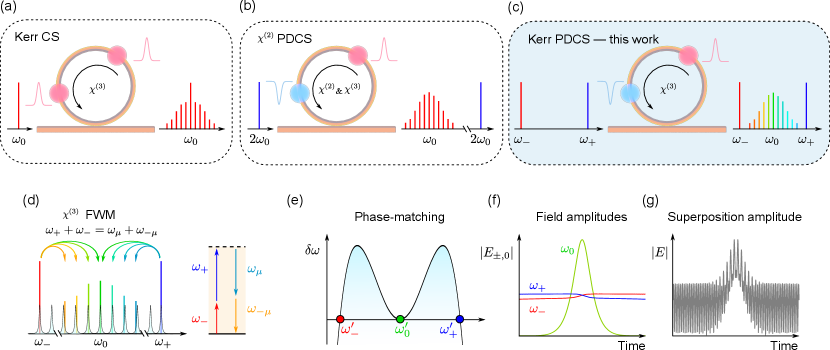
The injection of monochromatic continuous wave (CW) laser light into dispersive optical resonators with purely Kerr-type nonlinearity can lead to the generation of localized structures known as dissipative Kerr cavity solitons (CSs) leo_temporal_2010 ; kippenberg_dissipative_2018 . These CSs correspond to ultrashort pulses of light that can persist within the resonator [Fig. 1(a)], indefinitely maintaining constant shape and energy wabnitz_suppression_1993 . While first observed in macroscopic optical fiber ring resonators leo_temporal_2010 , CSs have attracted particular attention in the context of monolithic Kerr microcavities kippenberg_dissipative_2018 , where they underpin the generation of coherent and broadband optical frequency combs herr_temporal_2014 ; brasch_photonic_2016 ; pasquazi_micro-combs_2018 . By offering a route to coherent frequency comb generation in chip-integrated, foundry-ready platforms, CSs have enabled ground breaking advances in applications including telecommunications marin-palomo_microresonator-based_2017 ; corcoran_ultra-dense_2020 , artificial intelligence xu_11_2021 ; feldmann_parallel_2021 , astronomy suh_searching_2019 ; obrzud_microphotonic_2019 , frequency synthesis spencer_optical-frequency_2018 , microwave generation lucas_ultralow-noise_2020 ; kwon_ultrastable_2022 , and distance measurements suh_soliton_2018 ; riemensberger_massively_2020 .
The conventional CSs that manifest themselves in resonators with pure Kerr nonlinearity sit atop a CW background, and they gain their energy through four-wave-mixing (FWM) interactions with that background leo_temporal_2010 . In the frequency domain, the solitons are (to first order) centred around the frequency of the external CW laser that drives the resonator [Fig. 1(a)]. They are (barring some special exceptions nielsen_coexistence_2019 ; anderson_coexistence_2017 ; hansson_frequency_2015 ; xu_spontaneous_2021 ; lucas_spatial_2018 ) unique attracting states: except for trivial time translations, all the CSs that exist for given system parameters are identical. These features can be disadvantageous or altogether prohibitive for selected applications: noise on the external CW laser can degrade the coherence of nearby comb lines, removal of the CW background may require careful spectral filtering, whilst applications that require coexistence of distinguishable binary elements takesue_10_2016 ; okawachi_quantum_2016 ; okawachi_dynamic_2021 ; inagaki_Large-scale_2016 ; mohseni_ising_2022 are fundamentally beyond reach. Interestingly, recent experiments reveal that qualitatively different types of CSs can exist in resonators that display a quadratic in addition to a cubic nonlinearity [Fig. 1(b)]; in particular, degenerate optical parametric oscillators driven at can support CSs at englebert_parametrically_2021 ; bruch_pockels_2021 . In this configuration, the solitons are parametrically driven through the quadratic down-conversion of the externally-injected field, which endows them with fundamental differences compared to the conventional CSs emerging in monochromatically-driven, pure-Kerr resonators. Specifically, parametrically driven cavity solitons (PDCSs) are spectrally separated from the driving frequency (e.g. versus ), and they come in two binary forms with opposite phase. These traits render PDCSs of interest for an altogether new range of applications.
Optical PDCSs have so far been generated only via the quadratic nonlinearity, which is not intrinsically available in integrated (foundry-ready) resonator platforms, such as silicon thomson_roadmap_2016 or silicon nitride liu_high-yield_2021 ; luSHG2020 ; NitissNat.Photon.2022 . However, it is well-known that phase-sensitive amplification analogous to parametric down-conversion can also be realised in pure Kerr resonators when driven with two lasers with different carrier frequencies mecozzi_long-term_1994 ; agrawal_nonlinear_nodate ; radic_two-pump_2003 ; okawachi_dual-pumped_2015 ; Andrekson_fiber-based_2020 , allowing e.g. for novel random number generators takesue_10_2016 ; okawachi_quantum_2016 ; okawachi_dynamic_2021 and coherent optical Ising machines inagaki_Large-scale_2016 ; mohseni_ising_2022 . A natural question that arises is: is it possible to generate PDCSs in foundry-ready, pure-Kerr resonators with bichromatic driving? Whilst a related question has been theoretically explored in the context of diffractive Kerr-only resonators de_valcarcel_phase-bistable_2013 , the presence of dispersion substantially changes the physics of the problem. The impact of bichromatic driving in the dynamics of conventional Kerr CSs has also been considered hansson_bichromatically_2014 ; ceoldo_multiple_2016 ; zhang_spectral_2020 ; moille_ultra-broadband_2021 ; qureshi_soliton_2021 ; taheri_all-optical_2022 , but the possibility of using the scheme to generate temporal PDCSs remains unexplored.
Here, we theoretically predict and experimentally demonstrate that a dispersive resonator with pure Kerr nonlinearity can support PDCSs in the presence of bichromatic driving [Fig. 1(c)]. We reveal that, under appropriate conditions, a signal field with carrier frequency in between two spectrally-separated driving fields obeys the damped, parametrically driven nonlinear Schrödinger equation (PDNLSE) that admits PDCS solutions, and we unveil the system requirements for the practical excitation of such solutions. Our experiments are performed in a 23 m-radius, chip-integrated silicon nitride microring resonator whose dispersion is judiciously engineered to facilitate PDCS generation at 253 THz (1185 nm) when bichromatically pumping at 314 THz (955 nm) and 192 THz (1560 nm). We observe PDCS frequency comb spectra that are in good agreement with numerical simulations, as well as clear signatures of the anticipated symmetry, i.e., coexistence of two PDCSs with opposite phase. By revealing a fundamentally new pathway for the generation of coherent PDCS frequency combs far from any pump frequency, in a platform that has direct compatibility with foundry-ready fabrication, our work paves the way for integrated, low-noise frequency comb generation in new spectral regions, as well as photonic integration of applications requiring combs with a binary degree of freedom.
II Results
We first summarise the main points that lead to the prediction of PDCSs in bichromatically-driven Kerr resonators [for full details, see Methods]. To this end, we consider a resonator made out of a dispersive, nonlinear waveguide that is driven with two coherent CW fields with angular frequencies [see Fig. 1(c)]. The dispersion of the resonator is described by the integrated dispersion pasquazi_micro-combs_2018 at the cavity resonance (apostrophes highlight resonance frequencies throughout the article) closest to the frequency :
| (1) |
Here, is a relative mode number with respect to the resonance and is the cavity free-spectral range (FSR) at . The terms with account for deviations of the resonance frequencies from an equidistant grid defined by .
Under particular conditions [see Methods], the evolution of the slowly-varying electric field envelope centred at can be shown to be (approximately) governed by the PDNLSE, with the parametric driving ensuing from non-degenerate FWM driven by the intracavity fields at the pump frequencies [, see Fig. 1(d)]. (Note: in stark contrast to standard Kerr CSs, for which only one comb line is externally driven, all of the components of a PDCS frequency comb are separately driven via non-degenerate FWM.) Because the PDNLSE is well-known to admit PDCS solutions englebert_parametrically_2021 ; miles_parametrically_1984 ; barashenkov_stability_1991 , it follows that the system may support such solitons with a carrier frequency in between the two driving frequencies, provided however that the system parameters – particularly resonator dispersion – are conducive for soliton existence.
The resonator dispersion must meet three key conditions for PDCS excitation to be viable [Methods]. First, for solitons to exist, the dispersion around the degenerate FWM frequency must be anomalous, i.e., in Eq. (1). Second, the effective detuning [see Methods] between the degenerate FWM frequency () and the closest cavity resonance () must be within the range of soliton existence, essentially requiring that the degenerate FWM process (approximately) satisfies linear phase-matching [Fig. 1(e)]. This second condition can be written as , where correspond to the modes excited by the driving lasers at . Given that , this requires at least one higher-even-order dispersion coefficient (e.g. ) to be negative. Third, the intracavity field amplitudes at the driving frequencies, , must remain (approximately) homogeneous and stationary to ensure a constant parametric driving strength for the PDCS field centred at [Fig. 1(f)]. This final condition can be met by ensuring dispersion at the driving frequencies is (i) normal (or driving amplitudes small), such that the corresponding intracavity fields do not undergo pattern forming (modulation) instabilities coen_universal_2013 , and (ii) such that the temporal walk-off between the driving frequencies and the signal frequency is sufficiently large so as to mitigate pump depletion in the vicinity of the soliton that would otherwise break the homogeneity of the fields at [Fig. 1(f)]. As will be demonstrated below, all of these conditions can be met through judicious dispersion engineering that is within the reach of contemporary microphotonic fabrication.
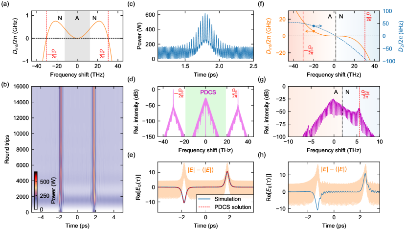
Simulations. Before discussing our experiments, we present results from numerical simulations that illustrate the salient physics. Our simulations are based upon a full iterative “Ikeda” map of the system without any approximations [Methods], and they consider a toy resonator with 25 GHz FSR and minimal dispersion necessary for PDCS existence [see Fig. 2(a)]. Specifically, we assume a quartic dispersion with and , yielding for pump frequency shift (corresponding to mode number ). We assume for simplicity that the two driving fields are coincident on their respective linear cavity resonances (zero detuning), and both carry CW laser power of about 140 mW [see Methods for other parameters]. Because the group-velocity dispersion at the pump frequencies is normal, modulational instabilities are suppressed and the intracavity fields converge to stable homogeneous states with equal circulating CW power of about 43 W, thus yielding an effective parametric driving strength and detuning within the regime of PDCS existence [see Methods].
Figure 2(b) shows the evolution of the numerically simulated intracavity intensity profile with an initial condition consisting of two hyperbolic secant pulses with opposite phases. As can be seen, after a short transient, the field reaches a steady-state that is indicative of two pulses circulating around the resonator. The pulses sit atop a rapidly oscillating background that is due to the beating between the quasi-homogeneous fields at the pump frequencies [Fig. 2(c)]. Correspondingly, the spectrum of the simulation output [Fig. 2(d)] shows clearly the presence of a hyperbolic secant-shaped feature that sits in between the strong quasi-monochromatic components at the pump frequencies. In accordance with PDCS theory [see Methods], there is no significant CW peak at the parametric signal frequency at which the solitons are spectrally centred. To highlight the phase disparity of the steady-state pulses, we apply a numerical filter to remove the quasi-monochromatic intracavity components around the pump frequencies, and plot in Fig. 2(e) the real part of the complex intracavity electric field envelope. The simulation results in Fig. 2(e) are compared against the real parts of the exact, analytical PDCS solutions [Methods], and we clearly observe excellent agreement.
The results in Fig. 2(a)–(e) corroborate the fundamental viability of our scheme. However, they were obtained assuming a completely symmetric dispersion profile with no odd-order terms, which may be difficult to realise even with state-of-the-art microphotonic fabrication (including the resonators considered in our experiments). We find, however, that PDCSs can exist even in the presence of odd-order-dispersion, albeit in a perturbed form. This point is highlighted in Figs. 2(f)–(h), which show results from simulations with all parameters as in Fig. 2(a)–(e) except an additional non-zero third-order dispersion term . As for conventional (externally-driven) Kerr CSs coen_modeling_2013 ; jang_observation_2014 ; milian_soliton_2014 ; brasch_photonic_2016 , we find that third-order dispersion causes the solitons to emit dispersive radiation at a spectral position determined by the phase-matching condition [Fig. 2(g)]. This emission results in the solitons experiencing constant drift in the temporal domain, and endows them with oscillatory tails [Fig. 2(h)]. Yet, as can clearly be seen, the PDCSs continue to exist in two distinct forms with near-opposite phase. It is worth noting that, for the parameters considered in Fig. 2(f)–(h), the low-frequency driving field experiences anomalous group-velocity dispersion; however, the intracavity intensity at that frequency is below the modulation instability threshold coen_universal_2013 , thus allowing the corresponding field to remain quasi-homogeneous (the modulation on the total intensity profile arises solely from the linear beating between the different fields).
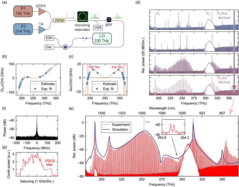
Experiments. For experimental demonstration [see Fig. 3(a) and Methods], we use a microring resonator made from a 690 nm-thick, 850 nm-wide silicon nitride layer embedded in fused silica, fabricated in a commercial foundry. The ring exhibits a radius of 23 m, thus yielding a free-spectral range of about 1 THz. We use two external cavity diode lasers to drive the resonator: one tunable in the telecommunications C-band (from 186 THz to 198 THz, i.e., from 1613 nm to 1515 nm) and the other tunable from 306 THz to 330 THz (980 nm to 910 nm). Both driving fields are optically amplified and combined using a wavelength-division multiplexer (WDM) before being coupled into the resonator via a pulley scheme that ensures efficient coupling at all the relevant frequencies moille_broadband_2019 . At the output of the resonator, 90% of the signal is routed to an optical spectrum analyzer for analysis. The remaining 10% is passed through a bandpass filter to remove spectral components around the driving frequencies, thus allowing to isolate the parametrically-generated signal field for characterisation.
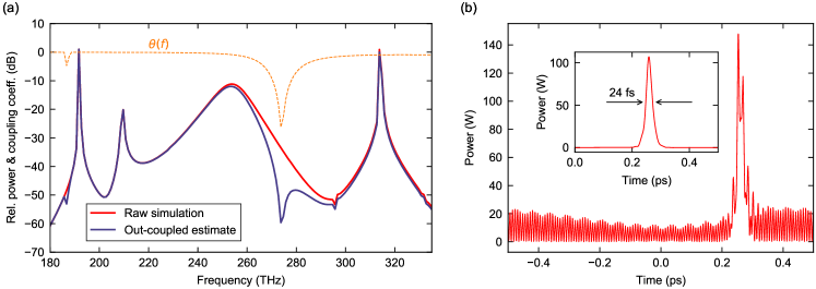
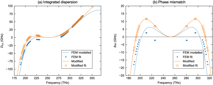
The orange curve in Fig. 3(b) depicts an estimate of the resonator’s integrated dispersion around a cavity mode at 253 THz, obtained through a combination of finite-element-modelling and fitting to our experimental observations [see Methods]. This data is consistent with experimentally measured resonance frequencies (blue circles), yet we caution that our inability to probe the resonances around 253 THz prevents unequivocal evaluation of the dispersion at that frequency. The estimated dispersion can be seen to be such that the requisite phase-matching for generating a PDCS at 253 THz () can be satisfied, provided that the pump lasers are configured to drive cavity modes at 314 THz and 192 THz [Fig. 3(c)].
In our experiments, we set the on-chip driving power for both driving fields to be about 150 mW and tune the high-frequency pump to the cavity mode at 314 THz. We then progressively tune the low-frequency pump to the cavity mode at 192 THz (from blue to red), maintaining the high-frequency pump at a fixed frequency. As the low-frequency pump tunes into resonance, we initially observe non-degenerate parametric oscillation characterised by the generation of two CW components symmetrically detuned about 253 THz. These CW components progressively shift closer to each other as the pump tunes into the resonance, concomitant with the formation of a frequency comb around the degenerate FWM frequency [see Fig. 3(c)]. To characterise the comb noise, we performed a heterodyne beat measurement using a helper laser at 230 THz within the vicinity of a single comb line. Initially, no beat note is observed, which is characteristic of an unstable, non-solitonic state within the resonator. Remarkably, as the 192 THz driving field is tuned further into resonance, we observe that the parametric signals reach degeneracy, concomitant with the emergence of a broadband comb state with smooth spectral envelope [Fig. 3(e)] and a heterodyne beat note (comparable with the helper laser linewidth of 250 kHz) that is considerably narrower than the 300 MHz microcavity linewidth [Fig. 3(f) and Supplementary Figure 1].
The emergence of the smooth comb state [Fig. 3(e)] is associated with an abrupt drop in the photodetector signal recorded around 253 THz, giving rise to a noticeable step-like feature [Fig. 3(f)]. Similar steps are well-known signatures of conventional CSs in monochromatically-driven Kerr resonators herr_temporal_2014 . Moreover, as shown in Fig. 3(e), the smooth spectral envelope observed in the step-region is in very good agreement with the spectrum of a 24 fs (full-width at half-maximum) PDCS derived from numerical modelling that use estimated experimental parameters [see Supplementary Figure 2]. The simulations faithfully reproduce the main features of the experimentally observed spectrum, including a strong dispersive wave peak at about 210 THz. We note that the prominent dip at about 275 THz arises due to the frequency-dependence of the pulley coupler moille_broadband_2019 , which was taken into account ad hoc when estimating the spectrum of the out-coupled PDCS [shown as blue curve in Fig. 3 – see also Methods and Supplementary Figure 2].
It is interesting to note that, in addition to the frequency comb around the degenerate FWM frequency 253 THz, frequency combs arise also around both of the pump frequencies. These combs originate from FWM interactions between the pump fields and the comb lines around 253 THz, in a manner similar to spectral extension zhang_spectral_2020 ; moille_ultra-broadband_2021 ; qureshi_soliton_2021 and two-dimensional frequency comb MoillearXiv2023 schemes studied in the context of conventional Kerr CSs. The combs around the pump frequencies share the line spacing with the comb around 253 THz, but there is a constant offset between the pump and PDCS combs. In our experiments, this comb offset is directly observable in the optical spectrum [inset of Fig. 3(e)] and found to be about 50 GHz 2 GHz (uncertainty defined by the optical spectrum analyzer resolution), which is in good agreement with the value of 49 GHz predicted by our modelling [see Methods]. All in all, given the considerable uncertainties in key experimental parameters (particularly dispersion and detunings), we find the level of agreement between the simulations and experiments remarkable.
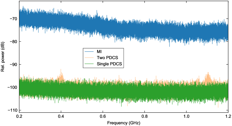
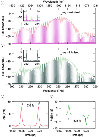
The results shown in Fig. 3 are strongly indicative of PDCS generation in our experiments. Further confirmation is provided by observations of low-noise combs with complex spectral structures that afford a straightforward interpretation in terms of multi-PDCS states [Fig. 4]. Specifically, whilst a single PDCS circulating in the resonator is expected to yield a smooth spectral envelope, the presence of two (or more) PDCSs results in a spectral interference pattern whose details depend upon the soliton’s relative temporal delay and – importantly – phase.
Figures 4(a) and (b) show selected examples of multi-soliton comb spectra measured in our experiments. Also shown as solid curves are spectral envelopes corresponding to fields with two linearly superposed, temporally delayed PDCSs [Figs. 4(c) and (d) and Methods]. We draw particular attention to the fact that, in the measured data shown in Fig. 4(b), the comb component at the degenerate FWM frequency is suppressed by about 40 dB compared to neighbouring lines, which is in stark contrast with results in Fig. 4(a), in which the degenerate FWM component is dominant. This suppression is indicative of a relative phase shift of between the two solitons [Fig. 4(d)] – a clear signature of PDCSs.
III Discussion
We have shown theoretically, numerically, and experimentally that dispersive resonators with a purely Kerr-type nonlinearity can support parametrically driven cavity solitons under conditions of bichromatic driving. Our theoretical analysis has revealed the salient conditions that the system dispersion must meet to allow for PDCS persistence, with approximation-free numerical simulations confirming the fundamental viability of the scheme. Experimentally, we realise suitable dispersion conditions in a chip-integrated silicon nitride microresonator, observing low-noise frequency comb states that evidence PDCS generation. Significantly, our measurements show spectral interference patterns that indicate the co-existence of two localized structures with opposite phase – a defining feature of PDCSs.
Our work fundamentally predicts and demonstrates that dispersive Kerr resonators can support a new type of dissipative structure – the PDCS – in addition to conventional Kerr CSs. We envisage that studying the rich nonlinear dynamics leo_dynamics_2013 ; yu_breather_2017 ; lucas_breathing_2017 , interactions jang_ultraweak_2013 ; cole_soliton_2017 ; wang_universal_2017 , and characteristics (including quantum chembo_quantum_2016 ; bao_quantum_2021 ; yang2021squeezed ; guidry_quantum_2022 ) of pure-Kerr PDCSs will draw substantial future research interest, echoing the extensive exploration of conventional Kerr CS dynamics over the past decade leo_dynamics_2013 ; yu_breather_2017 ; lucas_breathing_2017 ; jang_ultraweak_2013 ; cole_soliton_2017 ; wang_universal_2017 ; chembo_quantum_2016 ; bao_quantum_2021 ; yang2021squeezed ; guidry_quantum_2022 . In this context, to the best of our knowledge, the results reported in our work represent the first prediction and observation of dispersive wave emission by PDCSs in any physical system.
From a practical vantage, our scheme offers a route to generate PDCS frequency combs in foundry-ready, chip-integrated platforms with characteristics that are fundamentally different from those associated with conventional Kerr CSs. For example, forming between the two input frequencies, PDCSs could permit comb generation at spectral regions where direct pump lasers may not be available. Moreover, the lack of a dominating CW component at the PDCS carrier frequency alleviates the need for careful spectral shaping, and could result in fundamental advantages to noise characteristics. We emphasise that PDCSs are underpinned by phase-sensitive amplification mecozzi_long-term_1994 , which can theoretically offer a sub-quantum-limited (squeezed) noise figure McKinstrie_phase-sensitive_2004 ; slavik_all-optical_2010 ; tong_towards_2011 ; Zhang2008 ; Ye2021 . Finally, the fact that PDCSs come in two forms with opposite phase opens the doors to a new range of applications that require a binary degree of freedom, including all-optical random number generation and realisations of coherent optical Ising machines. Whilst the potential of PDCSs for such applications has been noted earlier englebert_parametrically_2021 , our work provides for the first time a route for chip-integrated realisations with potential to CMOS-compatible mass manufacturing.
Methods
Simulation models.
We first describe the theoretical models that describe the dynamics of bichromatically driven Kerr resonators and that underpin simulation results in our work. Our starting point is a polychromatic Ikeda-like map, which we will use to derive an extended mean-field Lugiato-Lefever equation that has been used in previous studies hansson_bichromatically_2014 ; taheri_optical_2017 ; zhang_spectral_2020 ; moille_ultra-broadband_2021 ; qureshi_soliton_2021 ; taheri_all-optical_2022 . To this end, we consider a Kerr resonator made out of a dispersive waveguide [with length and propagation constant ] that is driven with two coherent fields with angular frequencies [see Fig. 1(c)]. The evolution of the electric field envelope [referenced against the degenerate FWM frequency ] during the th transit around the resonator is governed by the generalized nonlinear Schrödinger equation:
| (2) |
Here is a coordinate along the waveguide that forms the resonator, is time in a reference frame that moves with the group-velocity of light at , is the Kerr nonlinearity coefficient and the dispersion operator
| (3) |
with the Taylor series expansion coefficients of around . Note that the single electric field envelope contains all the frequency components pertinent to the nonlinear interactions, including the fields at the pump frequencies and the signal frequency at . Note also that the Taylor series expansion coefficients are linked to the resonance frequency expansion coefficients in Eq. (1) as pasquazi_micro-combs_2018 , such that
| (4) |
The Ikeda map consists of Eq. (2) together with a boundary equation that describes the coupling of light into the resonator. Considering bichromatic driving, the boundary equation reads [see also Supplementary Note 1]:
| (5) |
Here is half of the fraction of power dissipated by the intracavity field over one round trip, is the linear phase detuning of the reference frequency from the closest cavity resonance (with order ), are the complex amplitudes of the driving fields at , respectively, with a positive integer represents the angular frequency shifts of the pumps from the reference frequency , and are the power transmission coefficients that describe the coupling of the driving fields into the resonator. The coefficients allow us to introduce the phase detunings that describe the detunings of the pump frequencies from the cavity resonances closest to them (thus accounting for the fact that the frequency shift may not be an exact integer multiple of ):
| (6) |
Note that the phase detunings described above are related to the frequency detunings of the corresponding carrier frequency from the closest cavity resonances at as .
Before proceeding, we note that, in our specific configuration, only two out of the three detuning terms introduced above ( and ) are independent. This is because the degenerate FWM frequency is completely determined by the pump frequencies viz. ; therefore, the signal detuning can be written in terms of the pump detunings as [see Supplementary Note 2]:
| (7) |
Substituting this expression for into Eq. (6) yields , where
| (8) |
It can be shown [see Supplementary Note 3] that this coefficient describes the offset, , between the frequency combs forming around and viz.
| (9) |
PDCS theory.
All of the simulations presented in our work use the full Ikeda-like map defined by Eqs. (2) and (5). However, the system’s ability to sustain PDCSs can be inferred more readily from the mean-field limit, obtained under the assumption that the intracavity envelope evolves slowly over a single round trip (i.e., the cavity has a high finesse, and the linear and nonlinear phase shifts are all small). In this case, the Ikeda-like map described above can be averaged into the generalized Lugiato-Lefever mean-field equation similar to the one used, e.g., in refs. zhang_spectral_2020 ; moille_ultra-broadband_2021 ; qureshi_soliton_2021 ; taheri_all-optical_2022 . We write the equation in normalized form as [see Supplementary Note 4]:
| (10) | ||||
Here is a slow time variable that describes the evolution of the intracavity field over consecutive round trips (and is thus directly related to the index of the Ikeda-like map), are the normalized strengths of the driving fields, is the normalized detuning of the signal field, and the normalized dispersion operator is defined as Eq. (3) but with normalized Taylor series coefficients . Finally, the coefficient
| (11) |
where are the normalized detunings of the external driving fields. To avoid notational clutter, we use the symbol to represent pump frequency shifts both in our dimensional and normalized equations.
We now make the assumption that the intracavity fields at the pump frequencies are homogeneous and stationary. (Note: this assumption is not used in any of our simulations.) To this end, we substitute the ansatz
| (12) | ||||
into Eq. (10). We then assume further that the (soliton) spectrum around the degenerate FWM frequency (the Fourier transform of ) does not exhibit significant overlap with the pump frequencies. This allows us to separate terms that oscillate with different frequencies, yielding the following equation for the signal field:
| (13) |
where the effective detuning with includes both linear and nonlinear (cross-phase modulation) phase shifts. Equation (13) has the precise form of the parametrically-driven nonlinear Schrödinger equation bondila_topography_1995 with effective detuning and parametric driving coefficient . Accordingly, assuming that the resonator group-velocity dispersion is anomalous at the signal frequency (), the equation admits exact (parametrically-driven) soliton solutions of the form englebert_parametrically_2021 :
| (14) |
where , , and . It should be clear from the last term of Eq. (13) that all of the frequency components of are parametrically driven. This is particularly evident when expanding the field as a Fourier series, : the equation of motion for each modal amplitude will include a parametric driving term .
Of course, the viability of sustaining the PDCS solution described by Eq. (14) in an actual bichromatically-driven Kerr resonator system is contingent on the applicability of the assumptions outlined above. As described in the main text, the assumption that the intracavity fields at the pump frequencies are homogeneous and stationary lead to the requirements of dispersive walk-off and suppression of modulation instabilities. The requirement for phase-matching of the degenerate FWM process ensues from the fact that stable PDCS solutions generically exist only if the effective detuning is sufficiently small bondila_topography_1995 . Indeed, recalling Eq. (7), we have
| (15) |
Considering typical parameters, and are of the order of unity for stable solitons to exist englebert_parametrically_2021 ; bondila_topography_1995 , while the detunings can be assumed small to ensure that sufficient intracavity powers can be attained without excessive driving powers . This implies, then, that the pump frequency shift must satisfy . Unpeeling the normalization, and converting to the integrated dispersion defined as Eq. (1) of the main text, shows that this condition is equivalent with the linear phase-matching of degenerate FWM: .
Resonator used in experiments.
The chip-integrated microring resonator used in our experiments was fabricated in a commercially-available foundry service. The resonators are made of a 690 nm-thick layer of silicon nitride that is fully embedded in fused silica. The ring has a width of 850 nm and a radius of 23 m, thus yielding a round trip length . Light is coupled into the ring via a 460 nm-wide integrated bus waveguide, with a 32 m-long pulley-coupler ensuring good coupling at all the different frequencies of interest (, ). The resonator has intrinsic and loaded -factors of and , respectively, corresponding to a finesse of and a resonance linewidth of . The chip has an input-to-output insertion loss of about 5.6 dB at 980 nm and 8.4 dB at 1550 nm.
Resonator dispersion and thermal nonlinearity.
The theoretically estimated resonator dispersion [orange curve shown in Fig. 3(b)] was obtained in two steps. We first calculated the theoretical resonance frequencies using finite-element modelling, and then slightly modified that data [see Supplementary Figure 3 for a comparison of the two integrated dispersion curves] to match the PDCS simulations to experimentally obtained spectra. Experimentally, we characterized the dispersion at various spectral regions by measuring the resonance frequencies using a set of widely tunable lasers and a high-resolution wavemeter. Unfortunately, the unavailability of a suitable laser around the degenerate FWM frequency (253 THz) prevented us from directly probing the dispersion at that frequency.
Because we are not able to probe the dispersion around 253 THz, it is not possible to unequivocally compare experimentally measured dispersion with our theoretical estimate. This is because the integrated dispersion depends upon the precise resonance frequency and the free-spectral range [] at , which we are unable to probe experimentally. To nonetheless show that our measurements at different spectral regions are consistent with our theoretical estimate, we can use nonlinear least-squares to fit our experimental data to the theoretical data, and in doing so obtain experimental estimates for and , which then allows us to compute the integrated dispersion. The blue dots in Fig. 3(a) were obtained using this procedure. The fitting also provides the one-standard-deviation errors for the parameter estimates, and , which then allows us to compute the fitting errors for and . We find that the maximum (across relative mode order ) error in the estimated is , yielding . These errors are smaller than the markers used in Figs. 3(b) and (c), which is why errorbars are not shown.
Due to the resonator’s small size, it exhibits a strong thermal nonlinearity carmon_dynamical_2004 . We leverage this effect to achieve self-stabilization, such that the input lasers can remain free-running but still maintain near-constant detunings. In addition, the thermal nonlinearity causes the resonance frequencies to shift over several GHz as the pump laser(s) are tuned into resonance [see e.g. Fig. 3(f)], which we suspect is key to achieving phase-matched operation (and thus PDCS generation). We also note that the thermal nonlinearity may influence the resonator dispersion directly moille_integrated_2022 ; whilst this effect is generally weak (and under-examined), it is possible that it also influences the precise phase-matching conditions, thus playing a role in our experiments. A detailed study on the impact of the thermal nonlinearity to PDCS generation is beyond the scope of our present work.
Simulation parameters.
The simulations in Fig. 2 assume a critically-coupled () resonator with a round trip length , nonlinearity coefficient , and finesse . The driving fields are positioned at an angular frequency shift with respect to the degenerate FWM frequency, corresponding to relative mode number . The dispersion coefficients are , and , corresponding to , and .
The above parameters yield an effective (normalised) driving strength and detuning which are known to be in the regime of soliton existence englebert_parametrically_2021 . As a matter of fact, the above parameters were found by looking for the driving powers and frequency shifts that yield these particular values for the driving strength and detuning.
The simulations in Fig. 3 and 4 use experimental values quoted in the main text or in the resonator description above, with the addition that the nonlinearity coefficient was set to . The pump detunings were chosen such that, in Fig. 3, the effective driving strength and , and in Fig. 4, and . The effective detunings were coarsely tuned so as to match the simulations to the experimentally measured spectra. The simulation outcomes are not sensitive to the particular values of the driving strength used.
Frequency-dependent coupling.
All the simulations reported in our manuscript have been obtained using the model defined by Eqs. (2) and (5). However, as explained in the main text [see also Supplementary Figure 2], when comparing against experimentally measured spectra [Figs. 3 and 4], the simulation outputs were post-processed to account for the frequency-dependent coupling, thus providing an estimate for the out-coupled spectrum. This was achieved by multiplying the simulated intracavity spectra with the frequency-dependent coupling coefficient [Supplementary Figure 2] obtained from rigorous coupled-mode simulations moille_broadband_2019 . These coupled-mode simulations assumed the coupler length to be 31.25 m, which was found to provide a better agreement with our experiments compared to the design value of m. This discrepancy is reasonable in terms of fabrication tolerances given the high sensitivity to the phase mismatch between the ring and waveguide modes and that any small discrepancy in the side-wall angle or waveguide width could cause a smaller effective pulley. However we note that the obtained length is well within fabrication tolerance of deep-UV stepper fabrication. Note that the frequency-dependent coupling was not included explicitly in our numerical simulation model for the sake of simplicity.
Multi-soliton states.
Because of pump depletion and finite dispersive walk-off, the PDCSs carve a depletion region onto the intracavity fields at the pump frequencies [see Fig. 1(f)]. These depletion regions are the time-domain manifestations of the frequency combs that form around the pump frequencies, and they give rise to long-range soliton interactions. Compounded by the system’s periodic boundary conditions, stable multi-soliton states only exist at selected relative delays (or not at all) in our simulations. On the other hand, it is well-known (from studies of conventional Kerr CSs) that experimental systems exhibit imperfections (e.g. avoided mode crossings) which, along with oscillatory tails from dispersive waves, force multi-soliton states to only manifest themselves at some prescribed relative delays cole_soliton_2017 ; wang_universal_2017 . Because the PDCSs in our simulations exhibit long-range coupling, it is not possible to obtain a simulation of a multi-soliton state with the same relative delays as in our experiments, unless one has access to full details of the experimental system (including dispersion that captures possible avoided mode crossings), which we do not have.
Because of the above, the theoretical PDCS fields in Fig. 4(c) and (d) were created from a single steady-state PDCS – obtained via simulations of Eqs. (2) and (5). Specifically, the two-soliton fields were obtained by linearly adding together two replicas of the single steady-state PDCS state, with the relative delay and phase between the replicas inferred from nonlinear least squares fitting to the experimentally observed spectral interference pattern. For both in- and out-of-phase states, our fitting algorithm yields two possible configurations that identically minimise the sum of the squared residuals. For the in-phase configuration, these are and , and for the out-of-phase configuration we have and . In Figs. 4(c) and (d), we plot the configurations associated with the larger delay. The one-standard-deviation errors for the fits are all smaller than .
Acknowledgements
G. M. and K. S. acknowledge support from the NIST-on-a-chip program. J. F. acknowledges the CNRS (IRP WALL-IN project).
Author Contributions
G. M. performed all the experiments and assisted in the interpretation of the results. M. L. and D. P contributed to the theoretical development of the scheme and performed initial simulations to confirm the fundamental viability of the scheme. N. E. and F. L. provided guidance on parametrically-driven soliton theory. J. F. assisted in the interpretation of Kerr cavity physics. K. S. supervised and obtained funding for the experiments. M. E. developed the theory, performed the simulations, and wrote the manuscript with input from all the authors.
Data availability
The data that support the plots within this paper and other findings of this study are available from M.E. upon reasonable request.
Competing financial interests
The authors declare no competing financial interests.
References
- (1) F. Leo, S. Coen, P. Kockaert, S.-P. Gorza, P. Emplit, and M. Haelterman, “Temporal cavity solitons in one-dimensional Kerr media as bits in an all-optical buffer,” Nature Photon 4, 471–476 (2010).
- (2) T. J. Kippenberg, A. L. Gaeta, M. Lipson, and M. L. Gorodetsky, “Dissipative Kerr solitons in optical microresonators,” Science 361 (2018).
- (3) S. Wabnitz, “Suppression of interactions in a phase-locked soliton optical memory,” Opt. Lett., OL 18, 601–603 (1993).
- (4) T. Herr, V. Brasch, J. D. Jost, C. Y. Wang, N. M. Kondratiev, M. L. Gorodetsky, and T. J. Kippenberg, “Temporal solitons in optical microresonators,” Nature Photon 8, 145–152 (2014).
- (5) V. Brasch, M. Geiselmann, T. Herr, G. Lihachev, M. H. P. Pfeiffer, M. L. Gorodetsky, and T. J. Kippenberg, “Photonic chip–based optical frequency comb using soliton Cherenkov radiation,” Science 351, 357–360 (2016).
- (6) A. Pasquazi, M. Peccianti, L. Razzari, D. J. Moss, S. Coen, M. Erkintalo, Y. K. Chembo, T. Hansson, S. Wabnitz, P. Del’Haye, X. Xue, A. M. Weiner, and R. Morandotti, “Micro-combs: A novel generation of optical sources,” Physics Reports 729, 1–81 (2018).
- (7) P. Marin-Palomo, J. N. Kemal, M. Karpov, A. Kordts, J. Pfeifle, M. H. P. Pfeiffer, P. Trocha, S. Wolf, V. Brasch, M. H. Anderson, R. Rosenberger, K. Vijayan, W. Freude, T. J. Kippenberg, and C. Koos, “Microresonator-based solitons for massively parallel coherent optical communications,” Nature 546, 274–279 (2017).
- (8) B. Corcoran, M. Tan, X. Xu, A. Boes, J. Wu, T. G. Nguyen, S. T. Chu, B. E. Little, R. Morandotti, A. Mitchell, and D. J. Moss, “Ultra-dense optical data transmission over standard fibre with a single chip source,” Nature Communications 11, 2568 (2020).
- (9) X. Xu, M. Tan, B. Corcoran, J. Wu, A. Boes, T. G. Nguyen, S. T. Chu, B. E. Little, D. G. Hicks, R. Morandotti, A. Mitchell, and D. J. Moss, “11 TOPS photonic convolutional accelerator for optical neural networks,” Nature 589, 44–51 (2021).
- (10) J. Feldmann, N. Youngblood, M. Karpov, H. Gehring, X. Li, M. Stappers, M. Le Gallo, X. Fu, A. Lukashchuk, A. S. Raja, J. Liu, C. D. Wright, A. Sebastian, T. J. Kippenberg, W. H. P. Pernice, and H. Bhaskaran, “Parallel convolutional processing using an integrated photonic tensor core,” Nature 589, 52–58 (2021).
- (11) M.-G. Suh, X. Yi, Y.-H. Lai, S. Leifer, I. S. Grudinin, G. Vasisht, E. C. Martin, M. P. Fitzgerald, G. Doppmann, J. Wang, D. Mawet, S. B. Papp, S. A. Diddams, C. Beichman, and K. Vahala, “Searching for exoplanets using a microresonator astrocomb,” Nature Photonics 13, 25–30 (2019).
- (12) E. Obrzud, M. Rainer, A. Harutyunyan, M. H. Anderson, J. Liu, M. Geiselmann, B. Chazelas, S. Kundermann, S. Lecomte, M. Cecconi, A. Ghedina, E. Molinari, F. Pepe, F. Wildi, F. Bouchy, T. J. Kippenberg, and T. Herr, “A microphotonic astrocomb,” Nature Photonics 13, 31–35 (2019).
- (13) D. T. Spencer, T. Drake, T. C. Briles, J. Stone, L. C. Sinclair, C. Fredrick, Q. Li, D. Westly, B. R. Ilic, A. Bluestone, N. Volet, T. Komljenovic, L. Chang, S. H. Lee, D. Y. Oh, M.-G. Suh, K. Y. Yang, M. H. P. Pfeiffer, T. J. Kippenberg, E. Norberg, L. Theogarajan, K. Vahala, N. R. Newbury, K. Srinivasan, J. E. Bowers, S. A. Diddams, and S. B. Papp, “An optical-frequency synthesizer using integrated photonics,” Nature 557, 81–85 (2018).
- (14) E. Lucas, P. Brochard, R. Bouchand, S. Schilt, T. Südmeyer, and T. J. Kippenberg, “Ultralow-noise photonic microwave synthesis using a soliton microcomb-based transfer oscillator,” Nature Communications 11, 374 (2020).
- (15) D. Kwon, D. Jeong, I. Jeon, H. Lee, and J. Kim, “Ultrastable microwave and soliton-pulse generation from fibre-photonic-stabilized microcombs,” Nature Communications 13, 381 (2022).
- (16) M.-G. Suh and K. J. Vahala, “Soliton microcomb range measurement,” Science 359, 884–887 (2018).
- (17) J. Riemensberger, A. Lukashchuk, M. Karpov, W. Weng, E. Lucas, J. Liu, and T. J. Kippenberg, “Massively parallel coherent laser ranging using a soliton microcomb,” Nature 581, 164–170 (2020).
- (18) A. U. Nielsen, B. Garbin, S. Coen, S. G. Murdoch, and M. Erkintalo, “Coexistence and Interactions between Nonlinear States with Different Polarizations in a Monochromatically Driven Passive Kerr Resonator,” Phys. Rev. Lett. 123, 013902 (2019).
- (19) M. Anderson, Y. Wang, F. Leo, S. Coen, M. Erkintalo, and S. G. Murdoch, “Coexistence of Multiple Nonlinear States in a Tristable Passive Kerr Resonator,” Phys. Rev. X 7, 031031 (2017).
- (20) T. Hansson and S. Wabnitz, “Frequency comb generation beyond the Lugiato–Lefever equation: multi-stability and super cavity solitons,” J. Opt. Soc. Am. B, JOSAB 32, 1259–1266 (2015).
- (21) G. Xu, A. U. Nielsen, B. Garbin, L. Hill, G.-L. Oppo, J. Fatome, S. G. Murdoch, S. Coen, and M. Erkintalo, “Spontaneous symmetry breaking of dissipative optical solitons in a two-component Kerr resonator,” Nat Commun 12, 4023 (2021).
- (22) E. Lucas, G. Lihachev, R. Bouchand, N. G. Pavlov, A. S. Raja, M. Karpov, M. L. Gorodetsky, and T. J. Kippenberg, “Spatial multiplexing of soliton microcombs,” Nature Photon 12, 699–705 (2018).
- (23) H. Takesue and T. Inagaki, “10 GHz clock time-multiplexed degenerate optical parametric oscillators for a photonic Ising spin network,” Opt. Lett., OL 41, 4273–4276 (2016).
- (24) Y. Okawachi, M. Yu, K. Luke, D. O. Carvalho, M. Lipson, and A. L. Gaeta, “Quantum random number generator using a microresonator-based Kerr oscillator,” Opt. Lett., OL 41, 4194–4197 (2016).
- (25) Y. Okawachi, B. Y. Kim, Y. Zhao, X. Ji, M. Lipson, M. Lipson, A. L. Gaeta, and A. L. Gaeta, “Dynamic control of photon lifetime for quantum random number generation,” Optica, OPTICA 8, 1458–1461 (2021).
- (26) T. Inagaki, K. Inaba, R. Hamerly, K. Inoue, Y. Yamamoto, and H. Takesue, “Large-scale Ising spin network based on degenerate optical parametric oscillators,” Nature Photon 10, 415–419 (2016).
- (27) N. Mohseni, P. L. McMahon, and T. Byrnes, “Ising machines as hardware solvers of combinatorial optimization problems,” Nat Rev Phys pages 1–17 (2022).
- (28) N. Englebert, F. De Lucia, P. Parra-Rivas, C. M. Arabí, P.-J. Sazio, S.-P. Gorza, and F. Leo, “Parametrically driven Kerr cavity solitons,” Nat. Photon. 15, 857–861 (2021).
- (29) A. W. Bruch, X. Liu, Z. Gong, J. B. Surya, M. Li, C.-L. Zou, and H. X. Tang, “Pockels soliton microcomb,” Nature Photonics 15, 21–27 (2021).
- (30) D. Thomson, A. Zilkie, J. E. Bowers, T. Komljenovic, G. T. Reed, L. Vivien, D. Marris-Morini, E. Cassan, L. Virot, J.-M. Fédéli, J.-M. Hartmann, J. H. Schmid, D.-X. Xu, F. Boeuf, P. O’Brien, G. Z. Mashanovich, and M. Nedeljkovic, “Roadmap on silicon photonics,” Journal of Optics 18, 073003 (2016).
- (31) J. Liu, G. Huang, R. N. Wang, J. He, A. S. Raja, T. Liu, N. J. Engelsen, and T. J. Kippenberg, “High-yield, wafer-scale fabrication of ultralow-loss, dispersion-engineered silicon nitride photonic circuits,” Nature Communications 12, 2236 (2021).
- (32) X. Lu, G. Moille, A. Rao, D. A. Westly, and K. Srinivasan, “Efficient photoinduced second-harmonic generation in silicon nitride photonics,” Nature Photonics pages 1–6 (2020).
- (33) E. Nitiss, J. Hu, A. Stroganov, and C.-S. Brès, “Optically reconfigurable quasi-phase-matching in silicon nitride microresonators,” Nature Photonics 16, 134–141 (2022).
- (34) A. Mecozzi, W. L. Kath, P. Kumar, and C. G. Goedde, “Long-term storage of a soliton bit stream by use of phase-sensitive amplification,” Opt. Lett., OL 19, 2050–2052 (1994).
- (35) G. Agrawal, “Nonlinear Fiber Optics - 5th Edition,” .
- (36) S. Radic and C. J. McKinstrie, “Two-pump fiber parametric amplifiers,” Optical Fiber Technology 9, 7–23 (2003).
- (37) Y. Okawachi, M. Yu, K. Luke, D. O. Carvalho, S. Ramelow, A. Farsi, M. Lipson, and A. L. Gaeta, “Dual-pumped degenerate Kerr oscillator in a silicon nitride microresonator,” Opt. Lett., OL 40, 5267–5270 (2015).
- (38) P. A. Andrekson and M. Karlsson, “Fiber-based phase-sensitive optical amplifiers and their applications,” Adv. Opt. Photon., AOP 12, 367–428 (2020).
- (39) G. J. de Valcárcel and K. Staliunas, “Phase-bistable Kerr cavity solitons and patterns,” Phys. Rev. A 87, 043802 (2013).
- (40) T. Hansson and S. Wabnitz, “Bichromatically pumped microresonator frequency combs,” Phys. Rev. A 90, 013811 (2014).
- (41) D. Ceoldo, A. Bendahmane, J. Fatome, G. Millot, T. Hansson, D. Modotto, S. Wabnitz, and B. Kibler, “Multiple four-wave mixing and Kerr combs in a bichromatically pumped nonlinear fiber ring cavity,” Opt. Lett., OL 41, 5462–5465 (2016).
- (42) S. Zhang, J. M. Silver, T. Bi, and P. Del’Haye, “Spectral extension and synchronization of microcombs in a single microresonator,” Nat Commun 11, 6384 (2020).
- (43) G. Moille, E. F. Perez, J. R. Stone, A. Rao, X. Lu, T. S. Rahman, Y. K. Chembo, and K. Srinivasan, “Ultra-broadband Kerr microcomb through soliton spectral translation,” Nat Commun 12, 7275 (2021).
- (44) P. C. Qureshi, V. Ng, F. Azeem, L. S. Trainor, H. G. L. Schwefel, S. Coen, M. Erkintalo, and S. G. Murdoch, “Soliton linear-wave scattering in a Kerr microresonator,” Communications Physics 5, 123 (2022).
- (45) H. Taheri, A. B. Matsko, L. Maleki, and K. Sacha, “All-optical dissipative discrete time crystals,” Nat Commun 13, 848 (2022).
- (46) J. W. Miles, “Parametrically excited solitary waves,” Journal of Fluid Mechanics 148, 451–460 (1984).
- (47) I. V. Barashenkov, M. M. Bogdan, and V. I. Korobov, “Stability Diagram of the Phase-Locked Solitons in the Parametrically Driven, Damped Nonlinear Schrödinger Equation,” Europhysics Letters 15, 113 (1991).
- (48) S. Coen and M. Erkintalo, “Universal scaling laws of Kerr frequency combs,” Opt. Lett., OL 38, 1790–1792 (2013).
- (49) S. Coen, H. G. Randle, T. Sylvestre, and M. Erkintalo, “Modeling of octave-spanning Kerr frequency combs using a generalized mean-field Lugiato–Lefever model,” Opt. Lett., OL 38, 37–39 (2013).
- (50) J. K. Jang, M. Erkintalo, S. G. Murdoch, and S. Coen, “Observation of dispersive wave emission by temporal cavity solitons,” Opt. Lett., OL 39, 5503–5506 (2014).
- (51) C. Milián and D. V. Skryabin, “Soliton families and resonant radiation in a micro-ring resonator near zero group-velocity dispersion,” Opt. Express, OE 22, 3732–3739 (2014).
- (52) G. Moille, Q. Li, T. C. Briles, S.-P. Yu, T. Drake, X. Lu, A. Rao, D. Westly, S. B. Papp, and K. Srinivasan, “Broadband resonator-waveguide coupling for efficient extraction of octave-spanning microcombs,” Optics Letters 44, 4737–4740 (2019).
- (53) G. Moille, C. Li, J. Stone, M. Chojnacky, P. Shandilya, Y. K. Chembo, A. Dutt, C. Menyuk, and K. Srinivasan, “Two-Dimensional Nonlinear Mixing Between a Dissipative Kerr Soliton and Continuous Waves for a Higher-Dimension Frequency Comb,” arXiv (2023).
- (54) F. Leo, L. Gelens, P. Emplit, M. Haelterman, and S. Coen, “Dynamics of one-dimensional Kerr cavity solitons,” Optics Express 21, 9180–9191 (2013).
- (55) M. Yu, J. K. Jang, Y. Okawachi, A. G. Griffith, K. Luke, S. A. Miller, X. Ji, M. Lipson, and A. L. Gaeta, “Breather soliton dynamics in microresonators,” Nature Communications 8, 14569 (2017).
- (56) E. Lucas, M. Karpov, H. Guo, M. L. Gorodetsky, and T. J. Kippenberg, “Breathing dissipative solitons in optical microresonators,” Nature Communications 8, 736 (2017).
- (57) J. K. Jang, M. Erkintalo, S. G. Murdoch, and S. Coen, “Ultraweak long-range interactions of solitons observed over astronomical distances,” Nature Photon 7, 657–663 (2013).
- (58) D. C. Cole, E. S. Lamb, P. Del’Haye, S. A. Diddams, and S. B. Papp, “Soliton crystals in Kerr resonators,” Nature Photonics 11, 671–676 (2017).
- (59) Y. Wang, F. Leo, J. Fatome, M. Erkintalo, S. G. Murdoch, and S. Coen, “Universal mechanism for the binding of temporal cavity solitons,” Optica, OPTICA 4, 855–863 (2017).
- (60) Y. K. Chembo, “Quantum dynamics of Kerr optical frequency combs below and above threshold: Spontaneous four-wave mixing, entanglement, and squeezed states of light,” Physical Review A 93, 033820 (2016).
- (61) C. Bao, M.-G. Suh, B. Shen, K. Şafak, A. Dai, H. Wang, L. Wu, Z. Yuan, Q.-F. Yang, A. B. Matsko, F. X. Kärtner, and K. J. Vahala, “Quantum diffusion of microcavity solitons,” Nature Physics 17, 462–466 (2021).
- (62) Z. Yang, M. Jahanbozorgi, D. Jeong, S. Sun, O. Pfister, H. Lee, and X. Yi, “A squeezed quantum microcomb on a chip,” Nature Communications 12, 4781 (2021).
- (63) M. A. Guidry, D. M. Lukin, K. Y. Yang, R. Trivedi, and J. Vučković, “Quantum optics of soliton microcombs,” Nature Photonics 16, 52–58 (2022).
- (64) C. J. McKinstrie and S. Radic, “Phase-sensitive amplification in a fiber,” Optics Express 12, 4973–4979 (2004).
- (65) R. Slavík, F. Parmigiani, J. Kakande, C. Lundström, M. Sjödin, P. A. Andrekson, R. Weerasuriya, S. Sygletos, A. D. Ellis, L. Grüner-Nielsen, D. Jakobsen, S. Herstrøm, R. Phelan, J. O’Gorman, A. Bogris, D. Syvridis, S. Dasgupta, P. Petropoulos, and D. J. Richardson, “All-optical phase and amplitude regenerator for next-generation telecommunications systems,” Nature Photonics 4, 690–695 (2010).
- (66) Z. Tong, C. Lundström, P. A. Andrekson, C. J. McKinstrie, M. Karlsson, D. J. Blessing, E. Tipsuwannakul, B. J. Puttnam, H. Toda, and L. Grüner-Nielsen, “Towards ultrasensitive optical links enabled by low-noise phase-sensitive amplifiers,” Nature Photonics 5, 430–436 (2011).
- (67) J. Zhang, C. Ye, F. Gao, and M. Xiao, “Phase-sensitive manipulations of a squeezed vacuum field in an optical parametric amplifier inside an optical cavity,” Phys. Rev. Lett. 101, 233602 (2008).
- (68) Z. Ye, P. Zhao, K. Twayana, M. Karlsson, V. Torres-Company, and P. A. Andrekson, “Overcoming the quantum limit of optical amplification in monolithic waveguides,” Science Advances 7, eabi8150 (2021).
- (69) H. Taheri, A. B. Matsko, and L. Maleki, “Optical lattice trap for Kerr solitons,” Eur. Phys. J. D 71, 153 (2017).
- (70) M. Bondila, I. V. Barashenkov, and M. M. Bogdan, “Topography of attractors of the parametrically driven nonlinear Schrödinger equation,” Physica D: Nonlinear Phenomena 87, 314–320 (1995).
- (71) T. Carmon, L. Yang, and K. J. Vahala, “Dynamical thermal behavior and thermal self-stability of microcavities,” Optics Express 12, 4742–4750 (2004).
- (72) G. Moille, D. Westly, E. F. Perez, M. Metzler, G. Simelgor, and K. Srinivasan, “Integrated buried heaters for efficient spectral control of air-clad microresonator frequency combs,” APL Photonics 7, 126104 (2022).
- (73) M. Haelterman, S. Trillo, and S. Wabnitz, “Dissipative modulation instability in a nonlinear dispersive ring cavity,” Optics Communications 91, 401–407 (1992).
IV Supplementary Note 1: Derivation of the Ikeda map
We present here a heuristic derivation of the Ikeda-like map used in our numerical simulations [Eq. (5) of the main manuscript]. Including the rapid temporal oscillations at , where are the input frequencies, the intracavity electric field during the cavity transit is written as , where is time in a co-moving reference frame defined as with absolute laboratory time, the coordinate along the waveguide that forms the resonator, the group velocity of light at , and is the slowly-varying electric field envelope that follows the generalized nonlinear Schrödinger equation [Eq. (2) of the main manuscipt]. The boundary equation for the full electric field can then be written as
| (16) |
where is the linear phase detuning of the reference frequency from the closest cavity resonance (with order ), and are the frequencies of the pump fields. Multiplying each side with and replacing where is the round trip time, yields
| (17) |
Note that, in the above formulation, the co-moving time variable should be understood as the “fast time” that describes the envelope of the intracavity electric field over a single round trip, i.e., the distribution of the envelope within the resonator pasquazi_micro-combs_2018 . As such, the variable spans a single round trip time of the resonator, and the intracavity envelope must obey periodic boundaries within that range. These conditions stipulate that the frequency variable , where is a positive integer and is the free-spectral range of the resonator. The fact that the frequency difference may not, in general, be an integer multiple of the FSR is captured by the additional phase shifts accumulated by the driving fields with respect to the intracavity field from round trip to round trip.
To link the frequency differences to the respective phase detunings, we first recall that the phase detuning of a driving field with frequency from a cavity resonance at obeys . We can thus write
| (18) |
where the frequency variables with (without) apostrophes refer to resonance (pump) frequencies. We next write the resonance frequencies as , where with the free-spectral range of the cavity (at ), an integer that represents the mode index (with corresponding to ), and the integrated dispersion
| (19) |
where are the expansion coefficients. Assuming that the resonance frequencies are associated with indices (with ), respectively, we can write Eq. (18) as
| (20) |
The second term on the right-hand-side of Eq. (20) can be ignored, as it yields an integer multiple of when used in Eq. (17). Next, we use the fact pasquazi_micro-combs_2018 that the coefficients with can be linked to the Taylor series expansion coefficients of the propagation constant viz. . This allows us to write the integrated dispersion corresponding to the resonance frequencies as
| (21) | ||||
| (22) |
Using Eq. (22) in Eq. (20) and substituting the latter into Eq. (17) yields the Ikeda-like map described by Eq. (5) of the main manuscript with coefficients as defined in Eq. (6) of the manuscript, and the pump frequency shift . We also note that the map can be straightforwardly extended to include arbitrarily many driving fields following the procedure above.
V Suplementary Note 2: signal detuning
To derive the relationship between the parametric signal detuning and the pump detunings (i.e., Eq. (7) of the main manuscript), we write out the parametric signal frequency as
| (23) |
where are the resonance frequencies closest to the pump frequencies and are the angular frequency detuning of the pump frequencies from those resonances. Substituting and expanding the pump resonance frequencies as yields
| (24) |
Then using Eq. (22) and rearranging, we obtain
| (25) |
This is Eq. (7) of the main manuscript.
VI Suplementary Note 3: comb offset
The boundary equation of the Ikeda-like map [Eq. (5) of the main manuscript] shows that the driving fields experience an additional relative phase shift per round trip determined by the coefficient
| (26) |
Using and , we obtain
| (27) |
By then using , we obtain
| (28) |
Given that , we recognise as the angular frequency shift between the pump at and the degenerate FWM signal at . Moreover, because the integer corresponds to mode number of the driven mode relative to , we may write
| (29) |
where is the angular frequency difference between the pump at and the closest component of the frequency comb (with spacing ) that forms around . Defining the ordinary comb offset as , and using the fact that the combs that form around and have the same spacing, we obtain
| (30) |
where we used .
VII Supplementary Note 4: Lugiato-Lefever equation and normalization
Under the assumption that the intracavity envelope evolves slowly over a single round trip (i.e., the cavity has a high finesse, and the linear and nonlinear phase shifts are all small), the Ikeda-like map described by Eqs. (2) and (5) of the main manuscript can be averaged into a single mean-field equation. The derivation is well-known haelterman_dissipative_1992 , proceeding by integrating Eq. (2) using a single step of the forward Euler method to obtain , which is then substituted into Eq. (5). After linearizing with respect to and and introducing the slow time variable (such that the round trip index ), one obtains:
| (31) |
To obtain the normalized Eq. (10) of the main manuscript, we first introduce the variable transformations , , and , yielding
| (32) | ||||
where , and . The normalized dispersion operator is defined as
| (33) |
where the normalized dispersion coefficients are given by
| (34) |
Finally, the coefficients , where are the normalized detunings of the external driving fields. Note that, for the particular configuration considered in our work, where the signal frequency is strictly linked to the pump frequencies via , the coefficients , where is defined by Eq. (11) of the main manuscript.