Parametrization of the Driven Betatron Oscillation
Abstract
An AC dipole is a magnet which produces a sinusoidally oscillating dipole field and excites coherent transverse beam motion in a synchrotron. By observing this coherent motion, the optical parameters can be directly measured at the beam position monitor locations. The driven oscillation induced by an AC dipole will generate a phase space ellipse which differs from that of the free oscillation. If not properly accounted for, this difference can lead to a misinterpretation of the actual optical parameters, for instance, of 6% or more in the cases of the Tevatron, RHIC, or LHC. The effect of an AC dipole on the linear optics parameters is identical to that of a thin lens quadrupole. By introducing a new amplitude function to describe this new phase space ellipse, the motion produced by an AC dipole becomes easier to interpret. Beam position data taken under the influence of an AC dipole, with this new interpretation in mind, can lead to more precise measurements of the normal Courant-Snyder parameters. This new parameterization of the driven motion is presented and is used to interpret data taken in the FNAL Tevatron using an AC dipole.
pacs:
41.85.-p, 29.27.-aI INTRODUCTION
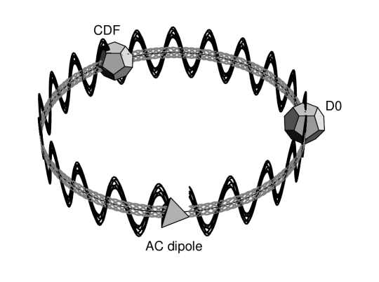
An AC dipole produces a sinusoidally oscillating dipole magnetic field and excites coherent transverse beam motion in a synchrotron for machine diagnosis (Fig 1). Unlike a conventional single turn kicker/pinger magnet, it drives the beam close to the betatron frequency typically for several thousands of revolutions. If the amplitude of its oscillating magnetic field is adiabatically ramped up and down, it can create large coherent oscillations without decoherence and emittance growth bai97 . This property makes it a useful diagnosis tool for a proton synchrotron, especially when it is used with an adequate beam position monitor (BPM) system.
AC dipoles have been used in the BNL RHIC bai01 ; bai02 and were also tested in the BNL AGS bai97 and CERN SPS berrig ; schmidt . Facilitated by its recently upgraded BPM system wolbers (now with a resolution of 20 m), a vertical AC dipole has been used in the FNAL Tevatron biw ; pacopt ; pacsys . There is an ongoing project to develop AC dipoles for LHC as well.
When the beam is driven by an AC dipole, the beam motion is governed by two driving terms and the influence of the lesser driving term makes the driven oscillation different from the free oscillation. Although this difference has typically been ignored in previous analyses bai02 ; peggs , it could affect the interpretation of the linear optics more than 12% in the Tevatron and 6% in the RHIC and LHC.
This paper proceeds as follows. Section II discusses the two driving terms produced by an AC dipole and presents a new formulation of the driven motion which is suited to treat the two driving terms at the same time. By introducing a new amplitude function for the driven motion, the difference between the free and driven oscillations becomes clear. Section III discusses the difference between the ordinary amplitude function for the free oscillation and the newly defined amplitude function for the driven oscillation . It is shown that the AC dipole has an analogy with a gradient error and, relative to , behaves as if there is a gradient error. Section IV presents a few properties of the driven motion which were observed in the Tevatron. The new formulation matches the observed data well.
II A MODEL OF THE DRIVEN OSCILLATION
II.1 Two Driving Terms of an Oscillating Dipole Field
The tune of an AC dipole is defined as the ratio between the frequencies of the AC dipole and the beam revolution : . In the following, for any tunes, only their fractional parts are considered. For instance, if is larger than one, means the fractional part of . Since the beam sees an AC dipole only once per revolution, the tune of an AC dipole and are equivalent (cf. Nyquist sampling theorem). Hence, under the influence of an oscillating dipole field a beam is driven by a pair of driving terms at and . Obviously, the driving term closer to the machine tune () has bigger effects on a beam. In the following, the driving term closer to is called the primary and the other is called the secondary. A symbol is used for the primary driving tune:
| (1) |
For example, the frequencies of the AC dipole and beam revolution in the Tevatron are kHz and kHz, respectively, and hence the tune of the AC dipole is . Since the machine tune of the Tevatron is , is the primary driving tune and is secondary in this case (Table 1).
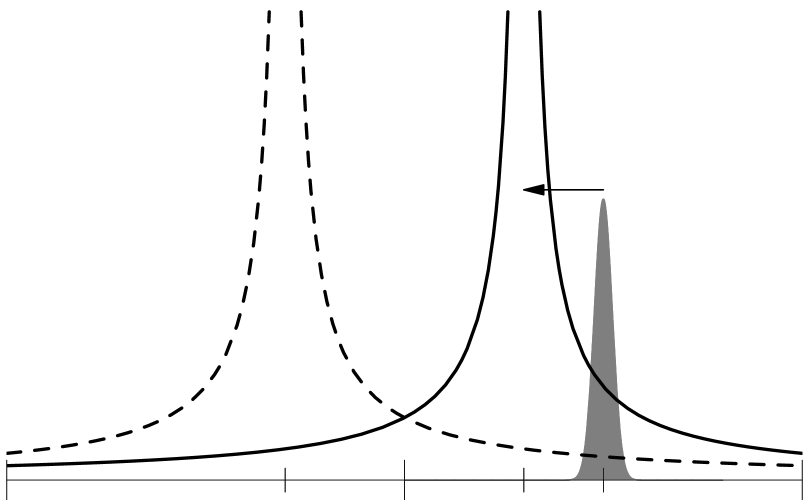
The distance from the primary driving term to the machine tune is an important parameter of the driven betatron oscillation. As seen later, the secondary driving term generates a difference between the free and driven oscillations and affects linear optics measurements. Ideally, if the beam is driven very close to the machine tune (), the influence of the primary driving term becomes dominant and the secondary driving term can be ignored. In reality, however, the finite tune spread of the beam causes beam losses if is too small and there is always a lower limit for (Fig 2). AC dipoles are currently used in the Tevatron and RHIC and planned for the LHC. In these synchrotrons, the lower limit of is about 0.01 to prevent beam losses.
When the amplitude of the field is constant, the position of the driven beam is given by peggs ; tomas
| (2) |
where is the circumference of a ring, is the longitudinal position measured from the location of the AC dipole, is the maximum kick angle of the AC dipole, is the amplitude function at the location of the AC dipole, is the phase advance of the free oscillation measured from the location of the AC dipole, and is the initial phase of the AC dipole. The two terms in Eq 2 are completely symmetric and represent the influences of the two driving terms 111Eq 2 is assuming the amplitude of the AC dipole field is adiabatically ramped up to a constant value. The exact expression of includes transient modes which are inversely proportional to the ramp up time and oscillate with the machine tune . If the ramp up is slow enough, all of these modes are very small and decohere before the end of the ramp up. Hence these ignored modes do not affect the motion of the beam centroid but they may affect the beam size tomas .. To quantify the effect of the secondary driving term, it is useful to define a parameter which describes the ratio between the primary (larger) and secondary (smaller) modes in Eq 2:
| (3) |
When , for the Tevatron with and for the RHIC and LHC with and (Table 1). This is the effect of the secondary driving term on the amplitude of the driven oscillation. When the machine tune is closer to the half-integer, the two driving terms are closer to each other and the influence of the secondary driving term gets larger. This is why of the Tevatron is larger than that of the RHIC and LHC.
| Parameter | Tevatron | RHIC | LHC |
|---|---|---|---|
| Machine Tune | .58 | .7 | .3 |
| AC Dipole Tune | .42 | .7 | |
| 6% | 3% | 3% | |
| Amplitude of the -beat | 12-13% | 6-7% | 6-7% |
II.2 A New Parametrization of the Driven Betatron Oscillation
Eq 2 can be written in the following compact form which includes the influences of both driving terms:
| (4) |
Here, is a quantity with dimensions of :
| (5) |
is a newly defined amplitude function of the driven oscillation which satisfies
| (6) |
is a newly defined phase advance of the driven oscillation measured from the location of the AC dipole:
| (7) |
and the sign in front of is positive when and negative when . Hence, the driven oscillation can be parametrized in the same form as the free oscillation even when the influences of the both driving terms are included. Since is a constant of motion, the difference between the free and driven oscillations comes from the amplitude function and phase advance . As discussed previously, in the limit, , the primary driving term becomes dominant and the secondary driving term can be ignored. In this limit and and converge to and .
If the lesser mode in Eq 2 is ignored, the oscillation phase has an apparent jump of at the location of the AC dipole. However, if the influences of both driving terms are properly included as Eq 4, the phase advance is smooth at the location of the AC dipole. A relation between the phase advances of free and driven oscillations, and , is given by
| (8) |
For the free oscillation, the phase advance in a single revolution is (mod ). In the equation above, when . Hence, the phase advance in a single revolution is for the driven motion.
III DIFFERENCE BETWEEN THE AMPLITUDE FUNCTIONS and
As seen in the previous section, the difference between the free and driven oscillations lies in the difference of their amplitude functions, and . It is crucial to understand this difference between and in detail when an AC dipole is used to diagnose a synchrotron.
In free betatron oscillations tune and amplitude function are coupled, and a change in tune involves a change in amplitude function and vice versa. This is true for the driven betatron oscillation, too. As seen in the previous section, for the driven oscillation, both the amplitude function and tune, and , are different from those for the free oscillation, and . As a matter of fact, the relation between these changes of the tune and amplitude function is the same as that for a gradient error. Hence, reviewing the effect of a gradient error is helpful to understand the driven oscillation.
III.1 Review of a Gradient Error
If a synchrotron has a gradient error, its machine tune and amplitude function change books . Suppose a synchrotron has a gradient error with the strength at the longitudinal position . Then, the equation of motion is given by
| (9) |
where the prime denotes the derivative with the longitudinal coordinate , is the spring constant, and is the Dirac’s delta function.
By comparing the single turn transfer matrices with and without the gradient error, the new tune and amplitude function satisfy the following two equations books :
| (10) | ||||
| (11) |
where is the amplitude function at the gradient error and is the phase advance measured from the gradient error. By substituting the first equation into the second, the ratio between the new and original amplitude functions is given by
| (12) |
Here, is a parameter similar to in Eq 3:
| (13) |
where is the tune shift by a gradient error . When the gradient error is small, the new and original amplitude functions satisfy
| (14) |
This quantity behaves like a standing wave in a synchrotron and is called the -beat (or sometimes -wave). The amplitude of the -beat is .
III.2 Analogy to a Gradient Error
As seen in Eqs 6 and 12, the relation between and for an oscillating dipole field is the same as the relation between and for a gradient error. The following argument gives insight why an oscillating dipole field changes the observed phase space motion as like a gradient error.
When the oscillation amplitude of the AC dipole field is constant, the Hill’s equation of motion is given by
| (15) |
The right-hand-side describes the kicks by the AC dipole located at . The summation runs over the time period when the oscillation amplitude of the AC dipole field is constant and the sign in front of the initial phase is the same convention as Eq 4. Eq 4 is the particular solution of this inhomogeneous Hill’s equation when the oscillation amplitude of the AC dipole field is adiabatically ramped to a constant amplitude. Since the phase of the driven oscillation increases by (mod ) in one revolution, the position of the driven oscillation at the location of the AC dipole is given by
| (16) |
Notice the phases of the driven oscillation and the kicks by the AC dipole in Eq 15 are both at the location of the AC dipole. Hence, when the beam passes the AC dipole, its magnetic field is proportional to the position of the driven oscillation like a quadrupole magnet. This is the physical reason why an oscillating dipole field changes the amplitude function like a gradient error. The phases of the driven oscillation and the AC dipole are synchronized like this only when the oscillation amplitude of the AC dipole field is constant after the adiabatic ramp up. Since is the solution of Eq 15, it formally satisfies the following equation
| (17) |
Here, Eq 16 is used to change the right-hand-side and is a constant given by
| (18) |
Eq 17 is exactly the same as the Hill’s equation with a gradient error, Eq 9. By comparing Eqs 9, 10, 18, and 17, it is trivial that the relation between and is the same as the relation between and .
III.3 Ring-wide Behavior of
As discussed in the previous two sections, for the driven motion, the observed amplitude function differs from the actual as if there is a gradient error. Hence, is beating relative to and the beating amplitude is about from Eq 14. Remember the effect of the secondary driving term on the beam motion is the order of . Since the amplitude function is proportional to the square of the position, its effect on the amplitude function is of the order of . Since the minimum difference between the primary driving tune and machine tune is about 0.01 for the Tevatron, RHIC, and LHC, the beating amplitude of relative to is 12-13% for the Tevatron and 6-7% for the RHIC and LHC (Table 1).
When turn-by-turn beam positions at all BPMs are given for the free oscillation, the relative -function can be determined by simply comparing the square of the oscillation amplitude at each BPM. If the same analysis is applied to the turn-by-turn data of the driven oscillation, what is calculated is instead of . If the difference between and is simply ignored and is determined in this way, the error may be as large as . Furthermore, since the beating of cannot be distinguished from the real -beat caused by gradient errors, the real -beat cannot be measured in this way without depending on a machine model.
To calculate the true -function from turn-by-turn data of the driven oscillation without depending on a machine model, multiple sets of data are necessary pacopt . Fig 3 shows amplitude functions of the free and driven oscillations, and . They are both measured from data of the driven oscillation. Multiple data sets are used to calculate as described in pacopt and is calculated by comparing the square of the amplitude at each BPM. As expected, is showing the beating of 10-15% relative to .

III.4 Relation between and
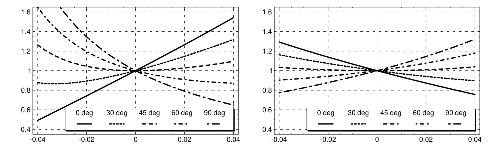
The previous section discussed the global behavior of compared to . This section considers how changes depending on at one location of a synchrotron. From Eq 6, the relation between and becomes nonlinear when is large or the phase term is close to zero. Since the difference between and has a considerable impact on the linear optics measurement, it is important to understand the properties of Eq 6 over wide ranges of parameters. Fig 4 shows the numerical calculations of based on Eq 6. The two plots are for two different machine tunes: like the Tevatron and like the RHIC and LHC. Since is almost twice as large for the same when compared to , the nonlinearity grows much faster with in the Tevatron. It is also seen in the left plot that the nonlinearity becomes larger when gets closer to zero. Such a nonlinear relation between and can be actually seen for the driven oscillation excited in the Tevatron. An example is shown in the next section.
IV EVIDENCE OF THE SECONDARY DRIVING TERM
IV.1 Rotation of the Phase Space Ellipse
The previous section discussed the amplitude function of the driven motion . Parameters corresponding to the other Courant-Snyder parameters and can be also defined as for the free oscillation:
| (19) | ||||
| (20) |
The explicit forms of these parameters are given by
| (21) |
and
| (22) |
When , , , and are defined this way, they satisfy the Courant-Snyder invariance:
| (23) |
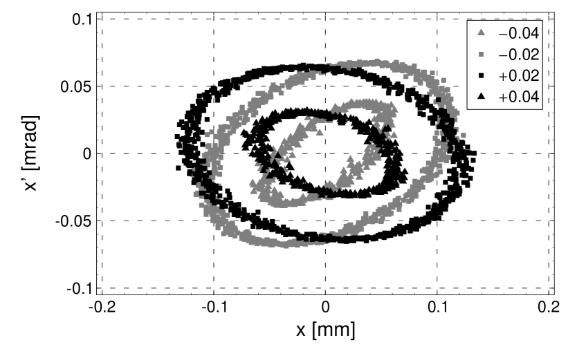
Hence, the turn-by-turn position and angle of the driven oscillation also form an ellipse on the phase space, like the free oscillation. Since not only but also the Courant-Snyder-like parameters , , and depend on the difference between the primary driving tune and the machine tune , both the area and shape of the phase space ellipse changes with for the driven oscillation. In two collision straight sections of the Tevatron, B0 and D0, there are pairs of BPMs with no magnetic element in-between. The beam travels along straight lines between these pairs and, hence, both position and angle can be directly measured at these locations. Fig 5 shows the measured phase ellipses of the driven oscillations by using a pair of such BPMs. The frequency of the AC dipole was changed to adjust to and , while the kick angle of the AC dipole was kept the same. As expected, the shape of the phase space ellipse changes with . Since dependence of , , and comes from the secondary driving term, the rotation of the phase space ellipse is its qualitative evidence.
By fitting Eq (23) to an ellipse in Fig 5, its area and the parameters , , and can be determined. Fig 6 shows determined from the fits to ellipses in Fig 5 (and three more). The curve in the figure is the fit of Eq 6 to the data with parameters and . The model of Eq 6 is fitting well to the data even though the nonlinearity is strong in the relation between and at the location. The -function at the location can be calculated as one of the fit parameters. In the figure it is the value of when .
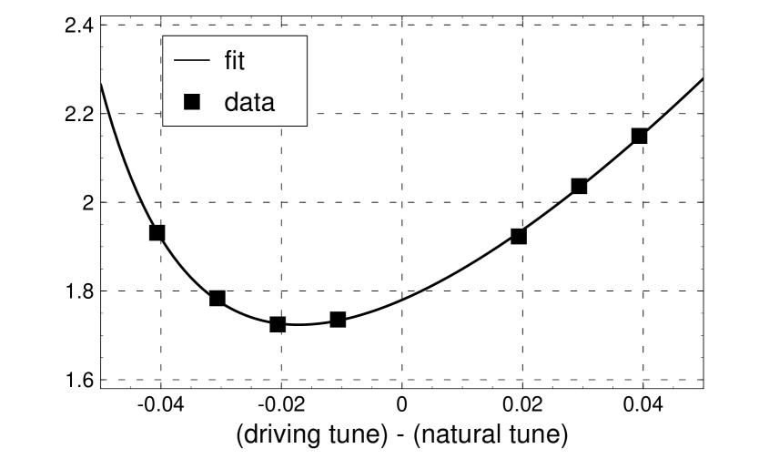
IV.2 Asymmetric Amplitude Response
When the secondary driving term is negligible, by ignoring the smaller term of Eq 2 or taking the limit of in Eqs 4, 5, and 6, the amplitude of the driven oscillation can be approximated by
| (24) |
In this case, the amplitude of the driven oscillation depends on the primary driving tune only through (remember ) and is symmetric around the machine tune . From Eqs 4, 5, and 6, the amplitude including the effect of the secondary driving term is given by
| (25) |
Now, the amplitude depends on through the factor as well. To the first order in , the amplitude is approximated by
| (26) |
Hence, the secondary driving term makes the dependence of the amplitude asymmetric around the machine tune . The magnitude of this asymmetry at each location is determined by the factor .
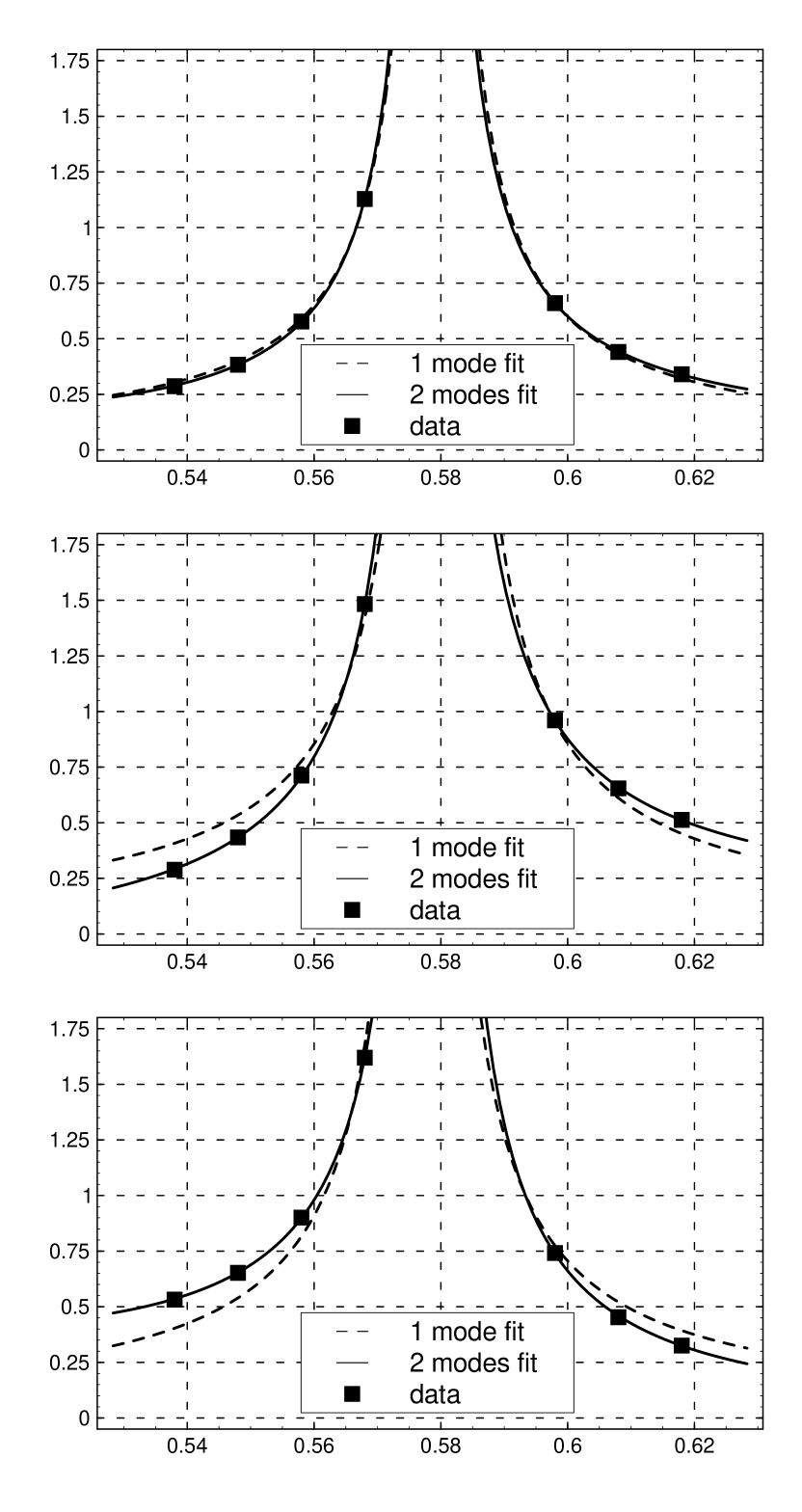
Fig 7 shows the relation between the amplitude of the driven oscillation and at three BPM locations in the Tevatron. In the measurements, only the frequency of the AC dipole was changed while its kick angle was kept the same. The dashed and solid lines represent the fits of Eq 24 and Eq 25 to the data. The fit parameters are and for Eq 24 and , , and for Eq 25 222The ring-wide -function can be determined from the fit up to a constant . The constant is determined from the analysis using a pair of BPMs in the collision straight sections. See pacopt for details. The phase advance can be determined for the fit, too.. At two locations where is close to one, the asymmetry around the machine tune () is large and the result of the fits without the secondary driving term (Eq 24) is not well matched.
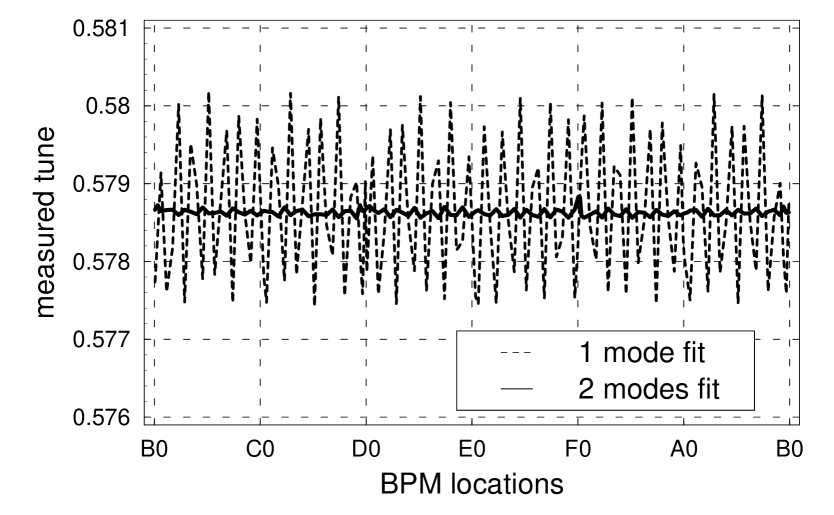
Although the existence of a secondary driven term effect is clear in Fig 7, there is better evidence that Eq 25 fits the data better than 24. From the fits in Fig 7, the machine tune can be determined at each BPM location. Fig 8 shows machine tunes determined at all BPM locations from the fits of the amplitude versus . The dashed and solid lines represent machine tunes from the fits of Eqs 24 and 25. Since the machine tune is a global parameter of a synchrotron, the variation of the measured machine tune over BPMs shows the inaccuracy of the measurement. From the figure, it is clear the model including the secondary driving fits to the data much better. This also shows the importance of the secondary driving term in the driven oscillation.
V CONCLUSION
Under the influence of a sinusoidally oscillating magnetic field of an AC dipole, the beam is driven by two driving terms. As a result the phase space trajectory of the driven motion is different from that of the free betatron motion. If the difference is simply ignored, interpretation of the linear optics based on the data of the driven motion can have 12-13% error for the Tevatron and 6-7% error for the RHIC and LHC. This difference on the phase space is identical to the influence of a gradient error at the same location as the AC dipole. Hence, as a gradient error changes the amplitude function around the ring, the expression of the driven motion can be simplified by introducing a new amplitude function for the driven motion.
This paper presented a few examples of the difference between the free and driven motions as observed in the Tevatron. It also showed that the new parametrization of the driven motion clarifies the data interpretation and multiple data sets are necessary to better resolve the true optical parameters of the free oscillation.
With this knowledge, very precise and direct measurements of the amplitude function in a hadron synchrotron can be obtained quickly without degradation of the beam quality, using a small number of data sets obtained at different frequencies of the AC dipole. This technique will be especially useful in the LHC, for example, to adjust the beam envelope at critical locations such as at beam collimation devices.
References
- (1) M. Bai et al., Phys. Rev. E 56, p. 6002 (1997).
- (2) M. Bai et al., in Proceedings of the 19th Particle Accelerator Conference, Chicago, Illinois, 2001 (IEEE, Piscataway, NJ, 2001), p. 3606.
- (3) M. Bai et al., in Proceedings of the 8th European Particle Accelerator Conference, Paris, France, 2002 (EPS-IGA and CERN, Geneva, 2002), p. 1115.
- (4) O. Berrig et al., in Proceedings of the 5th European Workshop on Beam Diagnostics and Instrumentation for Particle Accelerators, Grenoble, France, 2001 (ESRF, Grenoble, 2001), p. 82.
- (5) F. Schmidt et al., CERN Report No. AB-Note-2003-031 MD, 2003.
- (6) S. Wolbers et al., in Proceedings of the 21st Particle Accelerator Conference, Knoxville, Tennessee, 2005 (IEEE, Piscataway, NJ, 2005), p. 410.
- (7) R. Miyamoto et al., in Proceedings of the 12th Beam Instrumentation Workshop, Batavia, Illinois, 2006 (AIP, Melville, New York, 2006), p. 402.
- (8) R. Miyamoto et al., in Proceedings of the 22nd Particle Accelerator Conference, Albuquerque, New Mexico, 2007 (IEEE, Piscataway, NJ, 2007), p. 3465.
- (9) R. Miyamoto et al., in Proceedings of the 22nd Particle Accelerator Conference, Albuquerque, New Mexico, 2007 (IEEE, Piscataway, NJ, 2007), p. 3868.
- (10) S. Peggs, in Proceedings of the 18th Particle Accelerator Conference, New York, New York, 1999 (IEEE, Piscataway, NJ, 1999), p. 1572.
- (11) R. Tomas, Phys. Rev. ST Accel. Beams 8, 024401 (2005).
- (12) See standard textbooks of accelerator physics such as D. A. Edwards and M. J. Syphers, An Introduction to the Physics of High Energy Accelerators (John Wiley & Sons, Inc., New York, 1993) or S. Y. Lee, Accelerator Physics (Second Edition) (World Scientific, Singapore, 2004).
- (13) M. J. Syphers and R. Miyamoto, in Proceedings of the 22nd Particle Accelerator Conference, Albuquerque, New Mexico, 2007 (IEEE, Piscataway, NJ, 2007), p. 3495.