Periodic Array of Bose-Einstein Condensates in a Magnetic Lattice
Abstract
We report the realization of a periodic array of Bose-Einstein condensates of 87Rb F=1 atoms trapped in a one-dimensional magnetic lattice close to the surface of an atom chip. A clear signature for the onset of BEC in the magnetic lattice is provided by in-situ site-resolved radiofrequency spectra, which exhibit a pronounced bimodal distribution consisting of a narrow component characteristic of a BEC together with a broad thermal cloud component. Similar bimodal distributions are found for various sites across the magnetic lattice. The realization of a periodic array of BECs in a magnetic lattice represents a major step towards the implementation of magnetic lattices for quantum simulation of many-body condensed matter phenomena in lattices of complex geometry and arbitrary period.
pacs:
37.10.Gh, 37.10.Jk, 67.10.Ba, 67.85.HjOptical lattices based on arrays of optical dipole traps are used extensively to trap periodic arrays of ultracold atoms and quantum degenerate gases in a broad range of applications. These range from simulations of condensed matter phenomena Bloch08 to studies of low-dimensional quantum gases Kinoshita06 , high precision atomic clocks Takamoto05 and registers for quantum information processing Calarco00 ; Monroe07 . A potentially powerful alternative approach involves magnetic lattices based on periodic arrays of magnetic microtraps created by permanent magnetic microstructures Ghanbari06 ; Gerritsma06 ; Gerritsma07 ; Boyd07 ; Singh08 ; Whitlock09 ; Schmied10 ; Abdelrahman10 ; Llorente10 ; Leung11 ; Leung13 , current-carrying wires Yin02 ; Grabowsk03 ; Gunnther05 or vortex arrays in superconducting films Romero13 . Magnetic lattices based on patterned magnetic films may, in principle, be tailored to produce 2D (or 1D) arrays of atomic ensembles in arbitrary configurations Schmied10 . Periodicities may range from tens of micrometers, i.e., the interesting range for Rydberg-interacting quantum systems, such as Rydberg-dressed BECs Honer10 and Rydberg-mediated quantum gates Leung11 ; Saffman10 , down to below the optical wavelength where tunneling coupling strengths may exceed those possible with conventional optical lattices. Currently, there is also much interest in creating 2D periodic lattices of complex geometry, such as triangular, honeycomb, Kagome and super-lattices, in order to simulate condensed matter phenomena Lewenestein07 , including exotic quantum phases, such as graphene-like states Zhu07 ; Tarruell ; Uehlinger13 , which are predicted to occur in lattices with non-cubic symmetry.
Despite these prospects for magnetic lattices, little has been achieved to date, compared to optical lattices, in part due to the difficulty in controlling the resulting potentials, including magnetic homogeneity and efficient loading of the microtraps. Another serious challenge is to overcome the inelastic collision losses which can occur at high atom densities and which are accentuated when miniaturizing the traps. For example, previous experiments involving 2D arrays of magnetic microtraps with a period of about 25 m Whitlock09 were limited by rapid three-body loss (decay rates 20 s-1) which precluded the formation of Bose-Einstein condensates with observable condensate fractions.
In this Letter we report clear signatures for the realization of a periodic array of Bose-Einstein condensates (BECs) of 87Rb atoms in a 1D 10 m-period magnetic lattice. The signature for the onset of BEC is provided by in-situ site-resolved radio-frequency (RF) spectroscopy Whitlock09 ; Whitlock07 . To minimize three-body losses in the magnetic lattice the atoms are prepared in the low-field seeking state which has a three-times smaller three-body recombination coefficient Burt97 ; Soeding99 and weaker magnetic confinement than the state on which previous work was based Whitlock09 . Additionally, we employ lattice traps with lower trap frequencies and hence lower peak atom densities. The realization of a periodic array of BECs in a magnetic lattice represents a major step towards creating periodic arrays of BECs in more complex lattice geometries with smaller lattice periods which are required for simulation of many-body condensed matter phenomena.
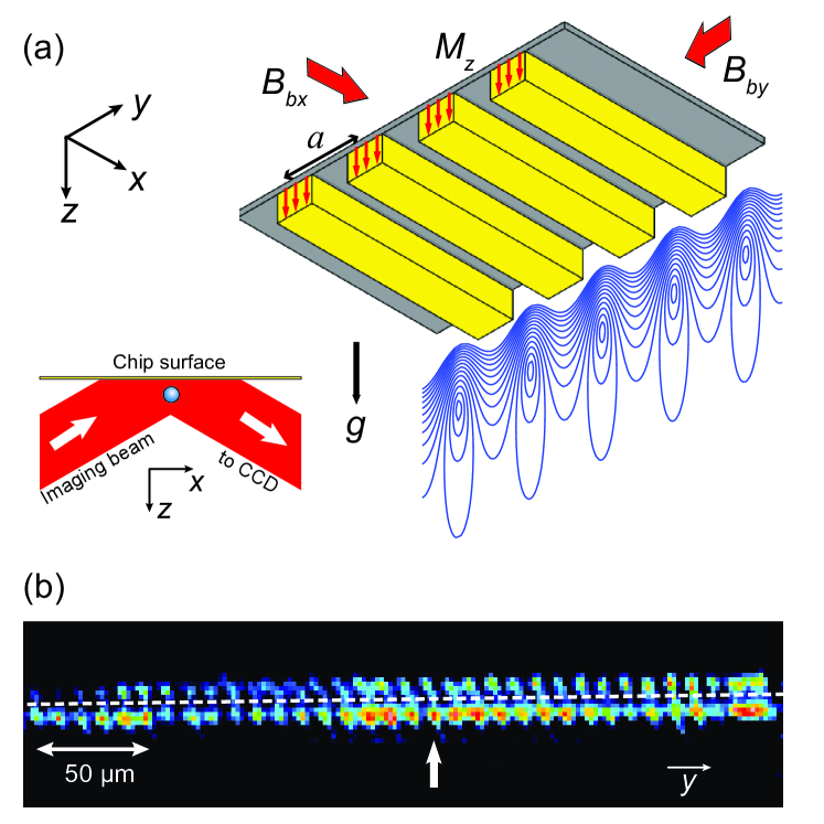
Our 1D lattice of magnetic microtraps is created by superimposing the magnetic field from a grooved, perpendicularly magnetized magnetic film with uniform bias fields and along the x- and y-directions (Fig. 1a) Ghanbari06 ; Singh08 . The magnetic field components in the case of an infinite 1D lattice with no axial confinement along the x-direction and for distances from the magnetic microstructure are [] [sin()e-kz+; B0cos()e-kz] Ghanbari06 , where is the lattice period, k=2, =4–1), t is the magnetic film thickness, and is the magnetization (in Gauss). A contour plot of calculated equipotentials, which are proportional to , is shown in Fig. 1a. The strength and direction of the bias fields determine the potential minima, their distance from the magnetic microstructure, the trap frequencies, and the barrier heights Ghanbari06 . The potential minima need to be non-zero to prevent losses due to Majorana spin-flips.
Details of the 1D 10 m-period magnetic microstructure and atom chip are described elsewhere Singh08 ; SJose13 . Briefly, the microstructure consists of a 10 mm10 mm magnetic film deposited on a microfabricated grooved silicon substrate on the atom chip, which is mounted upside-down in the UHV chamber. The magnetic film is a six-layer structure of 1.0 m-thick perpendicularly magnetized Tb6Gd10Fe80Co4 (total thickness 1.3 m), for which 3 kG, 6 kOe and 300oC Wang05 . The magnetic microstructure is mounted 300 m below a combined - and -wire oriented with its central section perpendicular to the grooves. The bias fields and weak axial confinement are provided by the current-carrying Z-wire SJose13 . For =17 A and =51 G, the trap frequencies determined from numerical simulations are =259 Hz and =7.3 kHz, which is consistent with =7.5 kHz measured by parametric heating. The trap frequencies correspond to a geometric mean frequency =2.40 kHz and an aspect ratio of 30. In comparison to earlier experiments on a 2D magnetic lattice Whitlock09 , is about four times smaller and, correspondingly, the expected three-body loss rates, which scale as Whitlock14 , are about 104 times smaller. The calculated barrier heights are =4 G (130 K) and 1 G (30 K).
Typically, 1108 87Rb atoms are collected in a mirror MOT 1.2 mm below the chip before being transferred to a compressed -wire MOT where they are polarization-gradient cooled and optically pumped to the state. The atoms are then transferred to a -wire trap 600 m below the chip where they are evaporatively cooled. About 3106 atoms at 10-15 K are then brought close to the magnetic lattice by ramping from 38 A down to 17 A in 100 ms with = 51 G. Under these conditions the Z-wire trap merges smoothly with the magnetic lattice microtraps located 8 m below the chip, allowing 1106 atoms to be loaded into the magnetic lattice SJose13 .
The lifetime of the atoms in the magnetic lattice microtraps is 12 s, which is sufficient for the atoms to be evaporatively cooled (for 1.5 s) by ramping an RF field from 7.0 MHz down to a final evaporation frequency . A trap depth of =)=100 kHz (where is the trap bottom) leaves 5104 atoms trapped in 100 lattice sites, or N500 atoms per site, in the central region of the lattice.
Figure 1b shows part of an in-situ absorption image for a periodic array of clouds of 87Rb atoms trapped in multiple sites of the 1D 10 m-period magnetic lattice after evaporative cooling to a trap depth =100 kHz, which cools the atoms below the critical temperature. The image was recorded using reflective absorption imaging Armijo10 along the long axis of the elongated atom clouds. The imaging beam is focused by a cylindrical lens into a light sheet and sent at a slight angle (2o) to the reflecting gold surface of the chip, resulting in images both after and prior to reflection. Detection of the two images provides a measure of the distance of the trapped atoms from the chip surface (8 m). The effective pixel size is 2.0 m, corresponding to 5.0 pixels per lattice period. The measured resolution from the width of the images of individual sites is 4 m.
The clouds of atoms in Fig. 1b are resolved in their individual lattice sites, which allows us to perform site-resolved measurements. The variation in site-to-site transmitted intensity (30) across the lattice is due mainly to imperfections in the gold mirror on the chip surface and to non-uniform loading of the lattice and non-uniformity of the imaging light. In addition, some of the variation is due to inhomogeneity in the magnetic lattice. The positions of the individual clouds of atoms reveal that the lattice period is constant to within 1 across the lattice.
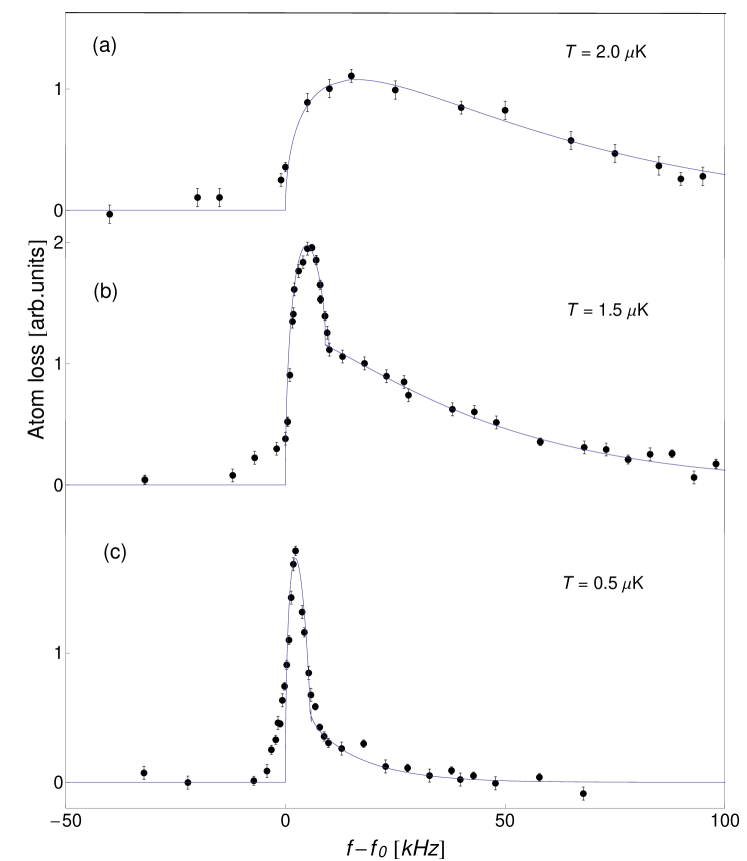
Figure 2 presents in-situ RF spectra of atom loss over a range of RF frequencies f taken at a single lattice site (site 38, vertical arrow in Fig. 1b) after the atoms have been evaporatively cooled to trap depths =600, 400 and 100 kHz. The power of the RF pulse was reduced to one-tenth of that used for evaporative cooling to minimize power broadening, and the RF pulse duration was 40 ms. The RF spectra evolve from (a) a broad truncated Boltzmann type frequency distribution for =600 kHz, characteristic of a thermal cloud, through to (c) a narrow Thomas-Fermi type frequency distribution for =100 kHz, characteristic of a BEC. For (b), =400 kHz, the RF spectrum exhibits a pronounced bimodal distribution consisting of BEC plus thermal cloud components Fernholz08 . The critical temperature for quantum degeneracy for N=500 atoms per site (=100 kHz) and =2.40 kHz is =0.9 K. The time decay of the BECs in the magnetic lattice corresponds to a half-life of 0.5 s.
To fit the data in Fig. 2, we use a self-consistent mean-field model which takes account of atom-atom interactions in both the BEC and thermal cloud and the mutual interaction between them Whitlock09 , but neglects the kinetic energy of the condensate fraction via the Thomas-Fermi approximation and effects of gravity sag in the tightly confining magnetic traps. For the density distribution of the condensates we use Gerbier04
| (1) |
where =Li is the density distribution of the thermal cloud, =++, and =1/2M( is the confining harmonic potential. Li3/2[z] is the polylogarithmic function with base 3/2, dB is the thermal de Broglie wavelength, g=4 is the mean-field coupling constant, is the atom mass, and is the s-wave scattering length. Equation 1 is solved iteratively to obtain for a given temperature T and chemical potential , where the elongated cloud with trap frequencies and can be replaced by a spherical cloud with mean trap frequency =. The RF frequency distribution is then obtained from the resonance condition = for =1 spin-flip transitions and by determining the number of atoms in a spherical shell 4 of constant frequency that are removed by a RF knife of width . For the case of a pure BEC, the number of trapped atoms removed by the RF knife at frequency f is with a base-width .
The solid lines in Fig. 2 represent fits to the RF spectra using the above model. For a given data set, and T are varied until the calculated RF spectrum provides a reasonable fit to the experimental spectrum with the constraint that the total atom number derived from and is consistent with the atom number Nabs derived from the absorption image and normalized to for various lattice sites. For the trap depth =400 kHz (Fig. 2b), the data fit well to a narrow BEC component plus a broad thermal cloud components with chemical potential =19 kHz, corresponding to N8700 atoms, and temperature T=1.5 K. The slight rounding of the leading edge of the spectrum is attributed to residual power broadening. For the trap depth =100 kHz (Fig. 2c), the fit yields =7.5 kHz, corresponding to N380 atoms, and T=0.50 K. The condensate fraction deduced from the fit is 50 (5), or 54 (5) if we include the contribution from the rounded leading edge in Fig. 2c.
| Site | (MHz) | (kHz) | T (K) | BEC (%) | Nabs(atoms) |
|---|---|---|---|---|---|
| 22 | 4.9318 (5) | 7.0 (1.0) | 0.55 (5) | 37 (5) | 240 (100) |
| 35 | 4.9320 (5) | 7.5 (0.5) | 0.50 (5) | 50 (5) | 510 (50) |
| 36 | 4.9322 (5) | 7.5 (0.5) | 0.50 (5) | 50 (5) | 430 (50) |
| 37 | 4.9323 (5) | 7.7 (0.5) | 0.58 (5) | 39 (5) | 430 (50) |
| 38 | 4.9322 (5) | 7.5 (0.5) | 0.50 (5) | 50 (5) | 460 (50) |
| 39 | 4.9322 (5) | 7.3 (0.5) | 0.52 (5) | 45 (5) | 490 (50) |
| 40 | 4.9324 (5) | 7.5 (0.5) | 0.55 (5) | 42 (5) | 480 (50) |
| 41 | 4.9324 (5) | 7.0 (0.5) | 0.55 (5) | 37 (5) | 370 (50) |
| 42 | 4.9324 (5) | 7.0 (0.5) | 0.55 (5) | 37 (5) | 400 (50) |
| 43 | 4.9320 (5) | 8.0 (0.5) | 0.60 (5) | 39 (5) | 320 (50) |
| 44 | 4.9325 (5) | 7.5 (0.5) | 0.53 (5) | 45 (5) | 430 (50) |
| 67 | 4.9320 (5) | 7.8 (0.5) | 0.60 (5) | 38 (5) | 440 (50) |
| 70 | 4.9319 (5) | 7.2 (0.5) | 0.56 (5) | 38 (5) | 390 (50) |
| 71 | 4.9320 (5) | 7.8 (0.5) | 0.55 (5) | 45 (5) | 460 (50) |
| 85 | 4.9320 (5) | 8.7 (1.0) | 0.60 (5) | 44 (5) | 450 (100) |
Our absorption imaging scheme allows RF spectra to be recorded simultaneously for all of the 100 populated sites across the magnetic lattice, with a total acquisition time of about one hour. The spectrum for each of the analyzed lattice sites exhibits a strong BEC component, similar to Fig. 2c. Table 1 summarizes the results for a sample of 15 sites which are representative of the central region (sites 23-85) of the lattice, including a string of 10 adjacent sites (35-44), and sites near the ends of the central region. The site-to-site variations in , , T and condensate fraction indicate that the sites are remarkably uniform across the lattice. In particular, the trap bottoms, which could be accurately determined from the intercepts of the fitted RF spectra with the () axis, show site-to-site variations of only 0.4 kHz corresponding to 0.6 mG in 7.0 G. This degree of uniformity across the lattice is not reflected in the absorption image in Fig. 1b or in the atom numbers derived from the absorption image which show significant variations in transmitted intensity as discussed above.
As an independent check for the onset of Bose-Einstein condensation in the magnetic lattice we measure the atom loss rate due to three-body recombination. For a BEC, the density-density fluctuations are suppressed relative to a thermal cloud, due to a factor of six smaller three-particle correlation function Burt97 . The three-body recombination loss rate is given by =, where is the loss rate constant. Assuming that during the atom loss the BEC maintains a Thomas-Fermi profile, the atom number decay becomes = where = and is the initial peak density of the condensate. The three-body recombination rate is measured by monitoring the atom loss for hold times out to 500 ms where the condensate still persists. A power-law fit to the atom decay curve yields an exponent of , which is consistent with the BEC value of but significantly different from the thermal cloud value of . For an initial peak density =, which was determined from analysis of the RF spectra, the three-body decay constant is found to be =, which is consistent with previous measurements for 87Rb atoms Burt97 ; Laburthe04 , but much smaller than the value = measured for a thermal cloud Burt97 .
Arrays of BECs in a 10 m-period magnetic lattice are promising for the implementation of Rydberg-interacting quantum systems by exploiting the long-range dipolar interaction between atoms excited to Rydberg states. The size of each BEC in the array is well within the typical Rydberg blockade radius, so that each BEC could potentially be used as a collective qubit. The interaction driven level shift between two n80s Rydberg excitations at a distance of 10 m is still several MHz, which far exceeds the Rydberg state decay rate Saffman10 . At the same time, each trap is sufficiently far from the chip surface to minimize unwanted surface effects Leung11 . It should also be possible to create spatially separated Rydberg-dressed BECs Honer10 or degenerate Fermi gases, in which Rydberg states are weakly admixed to the atoms, resulting in strong long-range and anisotropic interactions. This might enable the realization of ‘coupled quantum gases’ where atoms in spatially separated traps may strongly influence one another (e.g., Lakomy12 ).
Another application will be to engineer simple graphene-like model systems with tunable parameters, for example, using magnetic lattices with hexagonal symmetry loaded from a BEC or degenerate Fermi gas. In periodic lattices the tunneling rates scale with period a and barrier height as ] (where C=(32M)) Bloch08 . For a square optical lattice with a=0.64 m, the tunneling rate for 87Rb atoms is estimated to be J20 Hz for (where is the recoil energy) Bakr09 or J330 Hz for . Thus, in order to have significant tunneling rates in a magnetic lattice, sub-micron periods are required. Due to the tighter confinement, atomic states with low inelastic collision rates should be chosen (for example, fermionic atoms such as 40K) or the number of atoms per site should be limited to less than three, which would normally be the case for a 2D lattice with sub-micron period. Additionally, the magnetic potentials need to be smooth and homogeneous with constant periodicity (1-2% Romero13 ) and uniform trap bottoms. To produce high-quality magnetic potentials with sub-micron periods we propose to use nano-fabricated multi-atomic layer Co/Pd (or Pt) films (with 6 nm grain size) presently under development for high density data storage.
In conclusion, we have realized a periodic array of Bose-Einstein condensates in a 10 m-period 1D magnetic lattice. A clear signature for the onset of BEC was provided by in-situ site-resolved RF spectra which show a pronounced bimodal distribution. Similar bimodal distributions were found for various sites across the magnetic lattice. This result represents a major advance towards the implementation of magnetic lattices to create periodic arrays of BECs for quantum simulation of many-body condensed matter phenomena in lattices of complex geometry and arbitrary period .
We thank Mandip Singh, Brenton Hall and Chris Vale for fruitful discussions. We acknowledge funding from an ARC Discovery Project grant (DP130101160).
References
- (1) I. Bloch, J. Dalibard, and W. Zwerger, Rev. Mod. Phys. 80, 885 (2008).
- (2) T. Kinoshita, T. Wenger, and D. S. Weiss, Nature 440, 900 (2006).
- (3) M. Takamoto, F-L. Hong, R. Higashi, and H. Katori, Nature 435, 321 (2005).
- (4) T. Calarco et al., Phys. Rev. A. 61, 022304 (2000).
- (5) C. Monroe, Nature Phys. 416, 469 (2007).
- (6) S. Ghanbari, T. D. Kieu, A. Sidorov, and P. Hannaford, J. Phys. B 39, 847, (2006).
- (7) R. Gerritsma, and R. J. C. Spreeuw, Phys. Rev. A. 74, 043405 (2006).
- (8) R. Gerritsma et al., Phys. Rev. A 76, 033408 (2007).
- (9) M. Boyd et al., Phys. Rev. A 76, 043624 (2007).
- (10) M. Singh et al., J. Phys. B. 41, 065301 (2008).
- (11) S. Whitlock, R. Gerritsma, T. Fernholz, and R. J. C. Spreeuw, New J. Phys. 11, 023021 (2009).
- (12) R. Schmied, D. Leibfried, R. J. C. Spreeuw, and S. Whitlock, New J. Phys. 12, 012320 (2010).
- (13) A. Abdelrahman, M. Vasiliev, K. Alameh, and P. Hannaford, Phys. Rev. A 82, 012320 (2010).
- (14) I. Llorente Garcia et al., New J. Phys. 12, 093017 (2010).
- (15) V. Y. F. Leung, A. Tauschinsky, N. J. van Druten, and R. J. C. Spreeuw, Quant. Inf. Process. 10, 955 (2011).
- (16) V. Y. F. Leung et al., arXiv 1311.4512 (2013).
- (17) J. Yin, W. Gao, J. Hu and Y. Wang, Opt. Commun. 206, 99 (2002).
- (18) A. Grabowski and T. Pfau, Eur. Phys. J. D 22, 347 (2003).
- (19) A. Günther et al., Phys. Rev. A. 71, 063619 (2005).
- (20) O. Romero-Isart, C. Navau, A. Sanchez, P. Zoller, J. I. Cirac, Phys. Rev. Lett. 111, 145304 (2013).
- (21) J. Honer, H. Weimer, T. Pfau, and H. P. Büchler, Phys. Rev. Lett. 105, 160404 (2010).
- (22) M. Saffman, T. G. Walker, and K. Mlmer, Rev. Mod. Phys. 82, 2313 (2010).
- (23) M. Lewenstein et al., Adv. Phys. 56, 243 (2007).
- (24) S.-L. Zhu, B. Wang, and L.-M. Duan, Phys. Rev. Lett. 98, 260402 (2007).
- (25) L. Tarruell et al., Nature 483, 302 (2012).
- (26) T. Uehlinger et al., arXiv: 1308.4401 (2013).
- (27) S. Whitlock et al., Phys. Rev. A 75, 043602 (2007).
- (28) E. Burt et al., Phys. Rev. Lett. 79, 337 (1997).
- (29) J. Soeding et al., Appl. Phys. B 69, 257 (1997).
- (30) S. Jose, PhD Thesis, Swinburne University (2013).
- (31) J. Y. Wang et al., J. Phys. D 38, 4015 (2005).
- (32) S. Whitlock, C. F. Ockeloen, and R. J. C. Spreeuw, Phys. Rev. Lett. 104, 120402 (2010).
- (33) J. Armijo, T. Jacqmin, K. V. Kheruntsyan, and I. Bouchoule, Phys. Rev. Lett. 105, 230402 (2010).
- (34) T. Fernholz, R. Gerritsma, S. Whitlock, I. Barb, R. J. C. Spreeuw, Phys. Rev. A 77, 033409 (2008).
- (35) F. Gerbier et al., Phys. Rev. A 70, 013607 (2004).
- (36) B. Laburthe Tolra et al., Phys. Rev. Lett. 92, 190401 (2004).
- (37) K. Lakomy, R. Nath, and L. Santos, Phys. Rev. A. 85, 033618 (2012).
- (38) W. S. Bakr et al., Nature, 462, 74 (2009).