Quantum circuits for the preparation of spin eigenfunctions on quantum computers
Abstract
The application of quantum algorithms to the study of many-particle quantum systems requires the ability to prepare wavefunctions that are relevant in the behavior of the system under study. Hamiltonian symmetries are an important instrument, to classify relevant many-particle wavefunctions, and to improve the efficiency of numerical simulations.
In this work, quantum circuits for the exact and approximate preparation of total spin eigenfunctions on quantum computers are presented. Two different strategies are discussed and compared: exact recursive construction of total spin eigenfunctions based on the addition theorem of angular momentum, and heuristic approximation of total spin eigenfunctions based on the variational optimization of a suitable cost function. The construction of these quantum circuits is illustrated in detail, and the preparation of total spin eigenfunctions is demonstrated on IBM quantum devices, focusing on 3- and 5-spin systems on graphs with triangle connectivity.
I Introduction
One of the central goals of quantum mechanics is to determine the behavior of multiple interacting particles. A fundamental and important example is the determination of the eigenstates of spin Hamiltonians, especially those with the possibilities of frustration. Of particular richness is the behavior of spin liquids [1, 2], and signatures of spin-liquid behavior have been observed in a variety of magnetic materials [3, 4, 5].
Quantum spin liquids are exotic phases of matter featuring topological order and long-range quantum entanglement, which motivated the proposal and exploration of techniques to engineer such systems for topological protection of quantum information [6, 7]. To gain a more profound understanding of quantum spin liquids requires concerted experimental and computational efforts.
Digital quantum computers have been proposed as an alternative and complementary approach to the exploration of these strongly correlated quantum phases [8, 9]. Systems with frustration caused by the lattice geometry or long-range interactions have been identified as promising avenues in the search for quantum spin liquids [10, 11, 12, 13, 14, 15, 16]. Spin liquid behavior in frustrated quantum systems has been explored with a variety of computational platforms, namely annealers [17], superconducting quantum circuits [18, 19], and atom arrays [20].
Hamiltonian symmetries play a central role in the classification of Hamiltonian eigenfunctions, and in improving the efficiency and the accuracy of algorithms for the solution of the Schrödinger equation. The incorporation of symmetries in quantum simulation algorithms is an active research area with many important declinations, from qubit reduction [21, 22, 23, 24, 25], to careful design of state preparation circuits [26], to the introduction of symmetry violation penalties [27], to the adoption and refinement of post-selection and error-mitigation techniques. An important example, particularly for spin Hamiltonians, is spin symmetry: when a Hamiltonian operator commutes with the total spin and spin- operators, respectively and , there exists a basis of simultaneous eigenfunctions of and such constants of motion. Spin symmetry is encountered across a wide variety of situations relevant for the characterization of spin liquid behavior: from the Heisenberg model on a complete graph , to spin Hamiltonian providing a minimal model of magnetic correlations in molecular systems [28, 29], and the electronic structure of molecules and materials [30, 31, 32, 33, 34].
In this work, we explore quantum circuits for the synthesis of spin eigenfunctions on quantum computers. Previous approaches have typically concentrated on circuits for exact or controllably approximated encoding of general spin eigenstates [35], that require quantum resources (ancillae and multi-controlled multi-qubit gates) often beyond the capabilities of contemporary quantum hardware, or circuits for encoding of specific spin eigenstates [36, 37], that have less generality but require less quantum resources.
Here, we investigate the balance between generality, accuracy, and computational cost in the encoding of spin eigenfunctions by quantum circuits, by pursuing two approaches: an exact recursive construction of spin eigenstates, and a heuristic variational construction of approximate spin eigenstates.
The remainder of the present work is structured as follows. In Section II we present the two families of circuits studied in this work. In Section III we apply the proposed circuits to systems of 3 and 5 spin- particles on graphs with triangle connectivities, using classical simulators of quantum computers and quantum hardware. Conclusions are drawn in Section IV, and additional theoretical and implementation details are presented in the Appendix.
II Methods
In this Section, we describe our approaches to encode spin eigenstates on quantum computers. The exact recursive construction is presented in Subsection II.1, focusing on the structure and computational cost of the corresponding quantum circuits. The heuristic variational construction is presented in Subsection II.2, focusing on the Ansätze proposed and tested in the present work.
II.1 Exact recursive construction
In this Section, we consider a system of spin- particles, and our aim is to prepare such a system in an eigenfunction of the total spin operators and with eigenvalues and respectively, with , and . Following an established convention, we map the Hilbert space of a single spin-up particle onto that of a single qubit as
| (1) |
A single qubit can thus be prepared in a spin eigenfunction by applying to the initial state one of the following unitary transformations,
| (2) |
where denotes the Pauli operator, defined in Appendix B. A register of qubits can be prepared in a total spin eigenfunction using the quantum circuit shown in Figure 1, which uses a single gate, also defined in Appendix B.
| 0 | 0 | |||
|---|---|---|---|---|
| 1 | 1 | |||
| 1 | 0 | |||
| 1 | -1 |
In the remainder of this section, we will present a recursive procedure to prepare qubits in a total spin eigenfunction. For , such a preparation was shown in Figure 1.
Let us now show that the possibility to prepare qubits into a total spin eigenfunction implies the possibility to prepare qubits into a total spin eigenfunction. The starting point is the angular momentum addition theorem,
| (3) |
where , , and are eigenfunctions of the total spin operators with eigenvalues , and respectively, and is a Clebsch-Gordan coefficient. Here, our goal is to map onto a wavefunction of qubits. To this end, let us consider the case , so that Eq. (3) takes the form
| (4) |
By the induction hypothesis, can be mapped onto an -qubit wavefunction applying a quantum circuit to a register of qubits prepared in . Writing
| (5) |
for a suitable angle shows that the state can be mapped onto an -qubit wavefunction applying either of the the unitary transformations
| (6) | ||||
| (7) |
to a register of qubits prepared in . In Eq. (6) and (7), is a rotation of an angle applied to qubit , and the symbols and indicate application of a unitary transformation when qubit is in or respectively. The unitary transformations in Eq. (6) and (7) are equivalent to the quantum circuits shown in Figure 2.
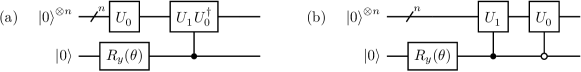
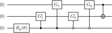
As a simple and relevant example, in Figure 3 we apply the exact recursive construction to spins. The gates , , , are defined as in the right portion of Figure 1, and implement the unitaries and respectively, with
| (8) |
Comparing Figures 2b and 3 shows that the latter circuit is simplified, in order to remove redundant gates.
II.1.1 Computational cost
Compared against previous approaches, the exact recursive construction presented here requires no ancillae [35], and applies to generic spin eigenfunctions [36]. However, it requires a number of single-qubit and gates scaling exponentially with .
This circumstance can be understood considering the structure in Figure 2. Constructing an -qubit total spin eigenfunction requires two controlled -qubit circuits and a single-qubit rotation. Denoting , the number of and single-qubit gates comprised by the -qubit circuit respectively, one can easily see that the -qubit circuit requires Toffoli, controlled single-qubit gates, and 1 additional single-qubit gate. By Lemmas 6.1 and 5.4 of [38] respectively, a Toffoli gate requires and 6 single-qubit gates, and a controlled single-qubit gate requires 2 and 2 single-qubit gates. Therefore, and .
Numeric integration of these recursion relations, with the initial conditions as seen in Figure 2, gives , which is exponential in the number of qubits. We remark that, in practice, circuit simplification techniques can lower this gate count, especially for total spin eigenfunctions with low entanglement.
II.2 Heuristic variational construction
The high computational cost of exact construction techniques for arbitrary spin eigenfunctions makes it desirable to propose less expensive alternative strategies, that are more suited to contemporary quantum devices. In this Section, we present a technique for heuristic variational construction of approximate total spin eigenfunctions.
Simulations of many-body ground- and excited-states on contemporary quantum hardware frequently make use of parametrized families of wavefunctions, of the form , where is a quantum circuit comprising free parameters, and is an initial wavefunction [39]. The best approximation to a target state within the set is chosen by minimizing a suitable cost function with respect to the parameters in the quantum circuit. A prominent example is the variational quantum eigensolver [40], where the target state is the ground state of a Hamiltonian operator , and the cost function is the expectation value of the Hamiltonian over the state . A natural choice for the cost function is
| (9) |
where denotes expectation value of an operator over the state . In the present work, we also consider the possibility to fix the total spin of one or more qubit subsets to a target value, respectively . To achieve this goal, we alter the cost function as follows,
| (10) |
where and denotes the total spin of subset . The functional takes value provided that is an eigenfunction of the operators , , and with eigenvalues , , and respectively.
The gradient of the cost function Eq. (10) is computed using the chain rule, and gradients of expectation values are computed analytically, rather than by finite differences, using a suitable shift formula [41, 42, 43, 44, 45].
II.2.1 Ansätze
The quality of a variational simulation depends not only on the cost function, but also on the underlying Ansatz, i.e. the map . In the present work, we explore several Ansätze, with the goal of assessing and comparing their accuracy and efficiently in the approximation of total spin eigenfunctions.
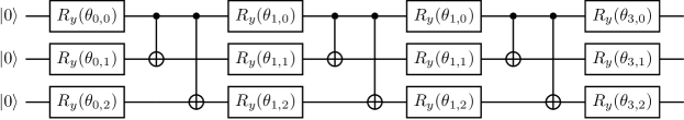
First, we consider the following Ansatz [46],
| (11) |
where is an initial wavefunction, is the number of qubits, is a rotation of an angle applied to qubit , is a gate acting on qubits , and is an integer denoting the number of times an entangling gate followed by a layer of rotations is repeated. The Ansatz is illustrated in Figure 4 for .
Next, we consider an Ansatz inspired by time evolution. Ref. [47] illustrated a recursive procedure for the preparation of an -qubit system in a total spin eigenfunction. An -qubit system is prepared in a total spin eigenfunction and coupled with a qubit prepared in . The system evolves under the action of a Heisenberg Hamiltonian with all-to-all coupling, , leading to the wave-function
| (12) |
Provided that the coefficients satisfy the relation
| (13) |
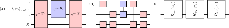
the state is a total spin eigenfunction with eigenvalues , . Motivated by this results, following and adapting the construction of the QAOA method [48], we introduce a variational form inspired by time evolution, shown in Figure 5. The Hamiltonian is represented as
| (14) |
and in Figure 5a the time evolution operator is approximated with the following primitive Trotter formula [49, 50, 51, 52],
| (15) |
In Figure 5b, we further impose the following primitive Trotter approximation,
| (16) |
and substitute each unitary with a parametrized two-qubit gate of the kind shown in Figure 5c.
III Results
Computational details.
We use IBM’s open-source Python library for quantum computing, Qiskit [53]. Qiskit provides tools for various tasks such as creating quantum circuits, performing simulations, and computations on quantum devices. It also contains an implementation of the VQE algorithm, a hybrid quantum-classical algorithm that uses both quantum and classical resources to variationally optimize the cost function, and a classical exact eigensolver algorithm, against which to compare results. We then minimize the expectation value of the cost function with respect to the parameters of the variational circuit. The minimization is carried out through a classical optimization method [54, 55, 56, 57, 58, 59]. In this work, we used the conjugate gradient [59] on the noiseless and deterministic statevectorsimulator of Qiskit. We then use the optimized parameters to compute expectation values on quantum hardware. We performed experiments on 5-qubit devices available through IBM Quantum Experience, each with a Quantum Volume [60] of 32, namely, ibmqathens, ibmqsantiago, and ibmqmanila [61].
Error mitigation.
We employed readout-error mitigation (EM) [62, 63, 64, 65] as implemented in Qiskit Ignis to correct measurement errors. We also used a noise extrapolation scheme, namely a simplified form of the Richardson extrapolation (RE), that uses additional gates at the minimum-energy VQE iterations to account for errors introduced by two-qubit entangling operations [66, 67]. More specifically, each gate in the circuit is replaced with a product of gates, , and the expectation value of an observable is extrapolated with a linear Ansatz,
| (17) |
Following Ref. [66], we call the ”noise parameter”.
Tomography.
An important goal of the present work is to assess how faithfully a quantum circuit executed on a quantum device approximates a target wavefunction . To answer this question, we compute the fidelity
| (18) |
between and the density operator prepared on the quantum hardware, and the purity of the former,
| (19) |
The density operator is measured by quantum tomography [68], and Eq. (18) and (19) are computed on the statevectorsimulator of Qiskit based on the measurement outcomes.
Target problems.
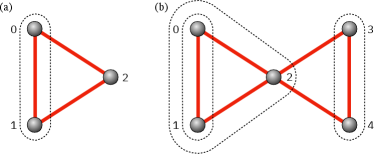
In the present work, we consider systems of and spins on graphs with triangle connectivity, illustrated in Figure 6. For 3-spin problems, our goal is to prepare total spin eigenfunctions starting from total spin eigenfunctions of the left spins (labeled 0,1 in Figure 6a). For 5-spin problems, we start from total spin eigenfunctions of the left spins (labeled 0,1 in Figure 6b and henceforth L), of the left and central spins (labeled 0,1,2 in Figure 6b and henceforth LC), and of the right spins (labeled 3,4 in Figure 6b and henceforth R).
III.1 Exact recursive construction
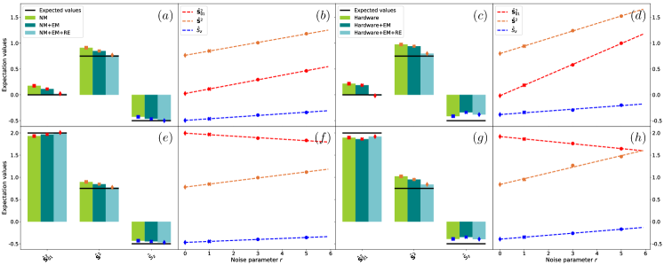
In Figure 7 we demonstrate the exact recursive construction for systems of spins prepared in the representative states and . We focus on the evaluation of the total spin operators (total spin of qubits 0 and 1), , and . As naturally expected, the use of EM and EM+RE significantly improves the agreement between exact and simulated values for these quantities.
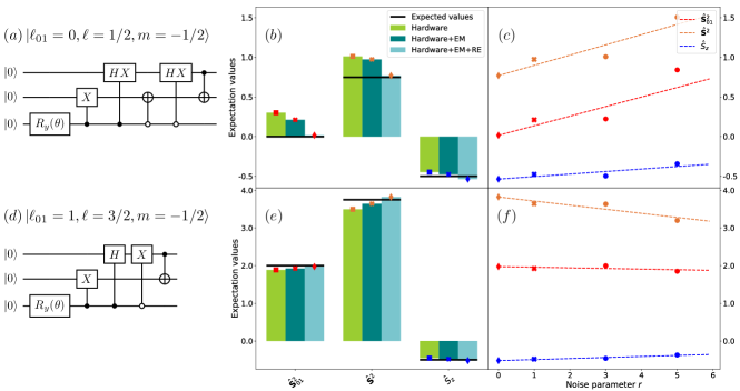
Two natural questions are whether the improved quality observed for expectation values of spin operators translates to generic observables, and what decoherence mechanisms are responsible for the deviations seen in raw hardware simulations.
To address these questions, in Table 1 we compute the fidelity and purity of the state , respectively Eq. (18) and (19). We observe , which mirrors the deviations between exact and simulated expectation values of spin operators. Furthermore, in raw hardware simulations, indicating that qubits are depolarized by decoherence. The combined use of EM+RE increases the fidelity towards 1, indicating a more faithful representation of the quantities measured on the device. Fidelities are extrapolated as shown in the right panel of Figure 8, where analogous results are presented for all the total spin eigenfunctions of qubits.
| (raw) | (raw) | (EM+RE) | |
|---|---|---|---|
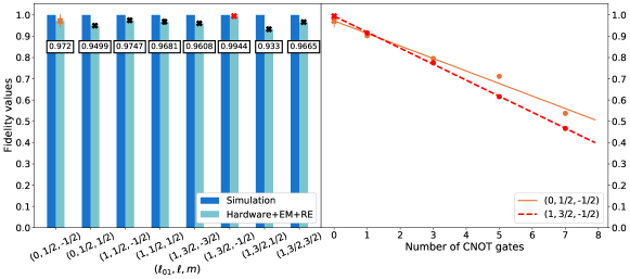
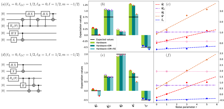
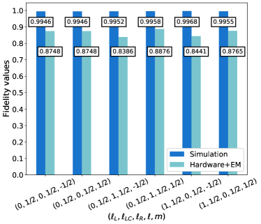
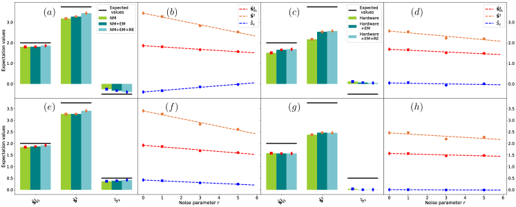
In Figure 9, we apply the exact recursive construction to systems of spins, using the qasmsimulator with noise model from ibmqathens, and ibmqathens. We focus on the states and . Although the trends seen for qubits, especially the beneficial impact of EM+RE techniques, are confirmed, a significant difference exists between Figures 7 and 9: in the latter case, error mitigation techniques do not close the gap between exact and simulated expectation values. The same phenomenon is observed in Figure 10, where we compute the fidelities between exact and simulated total spin eigenfunctions, for several representative states, using qasmsimulator and ibmqmanila. The different efficacy of error mitigation techniques for and qubits is an important observation of the present work, and it will be discussed in detail in the conclusions.
III.2 Heuristic variational construction
In this Section, we assess the accuracy and performance of VQE-based quantum circuits for approximate encoding of total spin eigenstates. Unlike in the case of exact recursive construction, variationally optimized circuits are not guaranteed to accurately approximate all the total spin eigenstates. For each Ansatz explored in the present work, we thus begin our analysis by assessing the Ansatz accuracy using classical simulators of noiseless quantum hardware, and we finally demonstrate the corresponding quantum circuits on IBM devices.
III.2.1 Ansatz
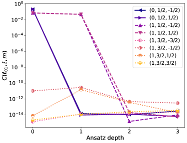
In Figure 11, we show the optimized cost function for the Ansatz with qubits and the connectivity in Figure 4, as a function of the Ansatz depth , as defined in Eq. (11). As seen, the choice ensures minimization of the cost function within single numeric precision across all spin eigenstates. In Table 2, we list the fidelity between the state and the target eigenstate . As seen, the fidelity is equal to 1 except for the Dicke states [69, 70, 71, 72, 73]. This is not unexpected, as the Dicke states are the most entangled -spin states, and therefore the most difficult targets for a variational optimization.
In Figure 12 we compute the spin operators , and using qasmsimulator with noise model from ibmqathens and on the device ibmqathens, and the Ansatz with depth . Similar trends are seen in both cases, with the combined use of EM+RE systematically improving results. It is clear that the noise models do not faithfully emulate the noise observe in our experiments, as readily seen when comparing the data in Figure 12. Given that the results are highly sensitive to noise affecting the qubits, it will be important to investigate these noise source further and determine the extent to which they can mitigated.
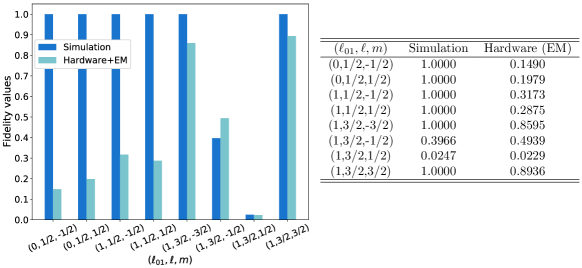
While the combination of EM and RE reduces the deviations between exact and simulated quantities, it does not completely remove them. To document this observation, in Figure 13 we compute the fidelity between optimal exact total spin eigenstates and VQE wavefunctions computed with statevectorsimulator (seen in Table 2) and on ibmqathens. As seen, decoherence significantly affects the fidelities of the obtained wavefunctions.
III.2.2 Time-evolution variational form
We now consider the time-evolution variational form. Unlike in the case of , where the initial state is customarily fixed to , here the initial state is set to
| (20) |
For repetitions, the time-evolution variational form returned and fidelity for all total spin eigenfunctions, including Dicke states. It should be noted, on the other hand, that to the better accuracy of the time-evolution variational form corresponds a higher computational cost, quantified in Table 3.
In Figure 14 we show the expectation values of the total spin operators for qubits, using the time-evolution variational form, computed with statevectorsimulator (seen in Table 2) and on ibmqsantiago. The higher computational cost of the time-evolution variational form, compared with the variational form, results in an increased sensitivity to noise, and ultimately in a worse agreement between exact and simulated quantities, a trend especially pronounced on the actual quantum device.
IV Conclusions
In this work, quantum circuits for the exact and approximate preparation of total spin eigenfunctions on quantum computers were presented. We described two families of circuits, representative of two different approaches to address this problem. First, we presented a recursive construction of total spin eigenfunctions based on the addition theorem of angular momentum, which we demonstrated for systems of 3- and 5-spin systems on graphs with triangle connectivity on IBM quantum devices. The approach is simple to understand and implement, and it guarantees exact mapping of total spin eigenfunctions on multi-qubit wavefunctions, without making use of ancillary qubits. On the other hand, its computational cost is at worst exponential in the number of qubits, which limits applications to large systems.
In addition, we presented a heuristic approximation of total spin eigenfunctions based on the variational optimization of a suitable cost function. The approach does not guarantee exact mapping of total spin eigenfunctions on multi-qubit wavefunctions. On the other hand, the heuristic variational approximation lends itself to simulations on contemporary quantum hardware, as it relies on families of quantum circuits whose computational cost can by construction be fit within the computational budget allowed by a certain device.
We show the effect of errors on the simulation of total spin eigenfunctions, by performing experiments on actual quantum devices. We observed that qubit decoherence and gate errors cause significant infidelities between target and simulated wavefunctions. The extent of such a phenomenon depends on the number of spins, as well as on the simulated circuit. We note particular problems with variational simulation of the most strongly correlated states, such as the Dicke states for spins, as well as topologies such as spins in a bow-tie, with the 4-way coordinated center spin.
Using the exact recursive construction, for qubits and qubits (as documented in Fig. 8 and 10), infidelities are 0.05 and 0.15 respectively, and roughly consistent across various spin eigenfunctions.
Larger and less uniform infidelities are seen for qubits when VQE is used (Fig. 13). These infidelities translate into significant deviations between exact and simulated observables, as seen in Fig. 14.
We demonstrate the effect of state-of-the-art error mitigation techniques to reduce the impact of measurement and gate errors on such results. To start with, systems with quits will have less error than , due to the different size and topology of these systems.
Of particular significance is the performance of the Richardson extrapolation, which breaks down for some of the qubits using exact recursive construction (see Fig. 9) and some of the qubits with very deep variational circuits (see Fig. 14). In the case of qubits, we ascribe this effect mainly to the problem of frequency crosstalk for the central qubit of the bowtie topology, which needs to couple to other closely valued but different frequency qubits. This problem will have to be solved if we are ever going to look at strongly coupled spin qubits in spin liquids. Ideally the next system to study would be the bow-tie (Figure 6) with the four corners (pairs (0,3) and (1,4)) also connected, with minimal connectivity 3.
Acknowledgments
AC and DEG acknowledge the Università degli Studi di Milano INDACO Platform for providing resources that have contributed to the results reported in this work. This material is based upon work supported by the U.S. Department of Energy, Office of Science, National Quantum Information Science Research Centers, Quantum Science Center.
Appendix A Structure of total spin eigenfunctions
In this Section, we list the total spin eigenfunctions explored in the present study, for and spins, respectively in Tables 4 and 5.
| 0 | ||||
|---|---|---|---|---|
| 0 | ||||
| 1 | ||||
| 1 | ||||
| 1 | ||||
| 1 | ||||
| 1 | ||||
| 1 |
| 0 | 0 | |||||
| 0 | 0 | |||||
| 0 | ||||||
| 0 | ||||||
| 0 | ||||||
| 0 |
Appendix B Quantum computing terms and symbols
In Table 6, we illustrate the quantum operations used in the present work. Single-qubit rotations are exponentials of single-qubit Pauli operators, for example . Single-qubit Pauli operators are equal to special single-qubit Pauli rotations up to a global phase, for example . Single-qubit operations in the Clifford group (Hadamard, and gates) are equal to special single-qubit Pauli rotations up to a global phase, namely , and .
The gate is sometimes denoted , where and are called the control and target qubit respectively, and applies an transformation to its target qubit ( symbol) if its control qubit ( symbol) is in the state , the can be written as a product of up to two gates and four single-qubit gates, and the gate can be written as a product of three gates, .
![[Uncaptioned image]](https://cdn.awesomepapers.org/papers/6b7f55b8-7e92-4b9a-b052-d6c005df427c/x15.png)
References
- Wen [2017] X.-G. Wen, Rev. Mod. Phys 89, 041004 (2017).
- Sachdev [2018] S. Sachdev, Rep. Prog. Phys 82, 014001 (2018).
- Fu et al. [2015] M. Fu, T. Imai, T.-H. Han, and Y. S. Lee, Science 350, 655 (2015).
- Banerjee et al. [2018] A. Banerjee, P. Lampen-Kelley, J. Knolle, C. Balz, A. A. Aczel, B. Winn, Y. Liu, D. Pajerowski, J. Yan, C. A. Bridges, et al., npj Quantum Materials 3, 1 (2018).
- Anderson [1987] P. W. Anderson, Science 235, 1196 (1987).
- Kitaev [2003] A. Y. Kitaev, Annals of Physics 303, 2 (2003).
- Nayak et al. [2008] C. Nayak, S. H. Simon, A. Stern, M. Freedman, and S. D. Sarma, Rev. Mod. Phys 80, 1083 (2008).
- Georgescu et al. [2014] I. M. Georgescu, S. Ashhab, and F. Nori, Rev. Mod. Phys 86, 153 (2014).
- Bauer et al. [2020] B. Bauer, S. Bravyi, M. Motta, and G. Kin-Lic Chan, Chem. Rev 120, 12685 (2020).
- Savary and Balents [2016] L. Savary and L. Balents, Rep. Prog. Phys 80, 016502 (2016).
- Rokhsar and Kivelson [1988] D. S. Rokhsar and S. A. Kivelson, Phys. Rev. Lett 61, 2376 (1988).
- Sachdev [1992] S. Sachdev, Phys. Rev. B 45, 12377 (1992).
- Misguich et al. [2002] G. Misguich, D. Serban, and V. Pasquier, Phys. Rev. Lett 89, 137202 (2002).
- Moessner and Sondhi [2001] R. Moessner and S. L. Sondhi, Phys. Rev. Lett 86, 1881 (2001).
- Read and Sachdev [1991] N. Read and S. Sachdev, Phys. Rev. Lett 66, 1773 (1991).
- Samajdar et al. [2021] R. Samajdar, W. W. Ho, H. Pichler, M. D. Lukin, and S. Sachdev, Proc. Natl. Acad. Sci. USA 118 (2021).
- Zhou et al. [2021] S. Zhou, D. Green, E. D. Dahl, and C. Chamon, Phys. Rev. B 104, L081107 (2021).
- Song et al. [2018] C. Song, D. Xu, P. Zhang, J. Wang, Q. Guo, W. Liu, K. Xu, H. Deng, K. Huang, D. Zheng, et al., Phys. Rev. Lett 121, 030502 (2018).
- Andersen et al. [2020] C. K. Andersen, A. Remm, S. Lazar, S. Krinner, N. Lacroix, G. J. Norris, M. Gabureac, C. Eichler, and A. Wallraff, Nat. Phys 16, 875 (2020).
- Semeghini et al. [2021] G. Semeghini, H. Levine, A. Keesling, S. Ebadi, T. T. Wang, D. Bluvstein, R. Verresen, H. Pichler, M. Kalinowski, R. Samajdar, A. Omran, S. Sachdev, A. Vishwanath, M. Greiner, V. Vuletić, and M. D. Lukin, Science 374, 1242 (2021).
- Bravyi et al. [2017] S. Bravyi, J. M. Gambetta, A. Mezzacapo, and K. Temme, arXiv preprint arXiv:1701.08213 (2017).
- Setia et al. [2020] K. Setia, R. Chen, J. E. Rice, A. Mezzacapo, M. Pistoia, and J. D. Whitfield, J. Chem. Theory Comput 16, 6091 (2020).
- Faist et al. [2020] P. Faist, S. Nezami, V. V. Albert, G. Salton, F. Pastawski, P. Hayden, and J. Preskill, Phys. Rev. X 10, 041018 (2020).
- Elfving et al. [2021] V. E. Elfving, M. Millaruelo, J. A. Gámez, and C. Gogolin, Phys. Rev. A 103, 032605 (2021).
- Eddins et al. [2022] A. Eddins, M. Motta, T. P. Gujarati, S. Bravyi, A. Mezzacapo, C. Hadfield, and S. Sheldon, PRX Quantum 3, 010309 (2022).
- Gard et al. [2020] B. T. Gard, L. Zhu, G. S. Barron, N. J. Mayhall, S. E. Economou, and E. Barnes, npj Quantum Inf 6, 1 (2020).
- Kuroiwa and Nakagawa [2021] K. Kuroiwa and Y. O. Nakagawa, Phys. Rev. Research 3, 013197 (2021).
- Logemann et al. [2017] R. Logemann, A. Rudenko, M. Katsnelson, and A. Kirilyuk, J. Phys. Cond. Mat 29, 335801 (2017).
- Schurkus et al. [2020] H. F. Schurkus, D. Chen, M. J. O’Rourke, H.-P. Cheng, and G. K.-L. Chan, J. Phys. Chem Lett 11, 3789 (2020).
- Sugisaki et al. [2018] K. Sugisaki, S. Nakazawa, K. Toyota, K. Sato, D. Shiomi, and T. Takui, ACS Cent. Sci 5, 167 (2018).
- Rost et al. [2020] B. Rost, B. Jones, M. Vyushkova, A. Ali, C. Cullip, A. Vyushkov, and J. Nabrzyski, arXiv preprint arXiv:2001.00794 (2020).
- Jones and Hore [2010] J. A. Jones and P. J. Hore, Chem. Phys. Lett 488, 90 (2010).
- Cao et al. [2019] Y. Cao, J. Romero, J. P. Olson, M. Degroote, P. D. Johnson, M. Kieferová, I. D. Kivlichan, T. Menke, B. Peropadre, N. P. Sawaya, et al., Chem. Rev 119, 10856 (2019).
- Motta and Rice [2021] M. Motta and J. E. Rice, WIREs Comput. Mol. Sci , e1580 (2021).
- Bacon et al. [2006] D. Bacon, I. L. Chuang, and A. W. Harrow, Phys. Rev. Lett 97, 170502 (2006).
- Sugisaki et al. [2019] K. Sugisaki, S. Yamamoto, S. Nakazawa, K. Toyota, K. Sato, D. Shiomi, and T. Takui, Chem. Phys. Lett X 1, 100002 (2019).
- Bärtschi and Eidenbenz [2019] A. Bärtschi and S. Eidenbenz, in Fundamentals of Computation Theory, edited by L. A. Gasieniec, J. Jansson, and C. Levcopoulos (Springer, 2019) pp. 126–139.
- Barenco et al. [1995] A. Barenco, C. H. Bennett, R. Cleve, D. P. DiVincenzo, N. Margolus, P. Shor, T. Sleator, J. A. Smolin, and H. Weinfurter, Phys. Rev. A 52, 3457 (1995).
- Cerezo et al. [2021] M. Cerezo, A. Arrasmith, R. Babbush, S. C. Benjamin, S. Endo, K. Fujii, J. R. McClean, K. Mitarai, X. Yuan, L. Cincio, et al., Nat. Rev. Phys , 1 (2021).
- Peruzzo et al. [2014] A. Peruzzo, J. McClean, P. Shadbolt, M.-H. Yung, X.-Q. Zhou, P. J. Love, A. Aspuru-Guzik, and J. L. O’Brien, Nat. Commun 5, 4213 (2014).
- McClean et al. [2016] J. R. McClean, J. Romero, R. Babbush, and A. Aspuru-Guzik, New J. Phys 18, 023023 (2016).
- Parrish et al. [2019] R. M. Parrish, E. G. Hohenstein, P. L. McMahon, and T. J. Martinez, arXiv preprint arXiv:1906.08728 (2019).
- Schuld et al. [2019] M. Schuld, V. Bergholm, C. Gogolin, J. Izaac, and N. Killoran, Phys. Rev. A 99, 032331 (2019).
- Mitarai et al. [2020] K. Mitarai, Y. O. Nakagawa, and W. Mizukami, Phys. Rev. Research 2, 013129 (2020).
- Kottmann et al. [2021] J. S. Kottmann, A. Anand, and A. Aspuru-Guzik, Chem. Sci 12, 3497 (2021).
- Kandala et al. [2017] A. Kandala, A. Mezzacapo, K. Temme, M. Takita, M. Brink, J. M. Chow, and J. M. Gambetta, Nature 549, 242 (2017).
- Sharma and Tulapurkar [2021] A. Sharma and A. A. Tulapurkar, Quantum Inf. Process 20, 1 (2021).
- Farhi et al. [2014] E. Farhi, J. Goldstone, and S. Gutmann, arXiv:1411.4028 (2014).
- Trotter [1959] H. F. Trotter, Proc. AMS 10, 545 (1959).
- Suzuki [1976] M. Suzuki, Comm. Math. Phys 51, 183 (1976).
- Childs et al. [2021] A. M. Childs, Y. Su, M. C. Tran, N. Wiebe, and S. Zhu, Phys. Rev. X 11, 011020 (2021).
- Childs and Su [2019] A. M. Childs and Y. Su, Phys. Rev. Lett 123, 050503 (2019).
- Aleksandrowicz et al. [2019] G. Aleksandrowicz, T. Alexander, P. Barkoutsos, L. Bello, Y. Ben-Haim, D. Bucher, F. Cabrera-Hernández, J. Carballo-Franquis, A. Chen, C. Chen, et al., Zenodo 16 (2019).
- Kingma and Ba [2014] D. P. Kingma and J. Ba, arXiv preprint arXiv:1412.6980 (2014).
- Stokes et al. [2020] J. Stokes, J. Izaac, N. Killoran, and G. Carleo, Quantum 4, 269 (2020).
- Spall [1998] J. C. Spall, Johns Hopkins APL Tech. Dig. 19, 482 (1998).
- Spall [1998] J. C. Spall, in Proc. IEEE Conf. Decis. Control, Vol. 4 (1998) pp. 3872–3879.
- Bhatnagar et al. [2013] S. Bhatnagar, H. Prasad, and L. Prashanth, Stochastic recursive algorithms for optimization: simultaneous perturbation methods (Springer, 2013).
- Hestenes et al. [1952] M. R. Hestenes, E. Stiefel, et al., Methods of conjugate gradients for solving linear systems, Vol. 49 (NBS Washington, DC, 1952).
- Cross et al. [2019] A. W. Cross, L. S. Bishop, S. Sheldon, P. D. Nation, and J. M. Gambetta, Phys. Rev. A 100, 032328 (2019).
- ibmqathens v1.3.1, ibmqsantiago v1.2.1, and ibmqmanila v1.1.1 [2020] ibmqathens v1.3.1, ibmqsantiago v1.2.1, and ibmqmanila v1.1.1, IBM Quantum Team, Retrieved from https://quantum-computing.ibm.com (2020).
- Temme et al. [2017] K. Temme, S. Bravyi, and J. M. Gambetta, Phys. Rev. Lett 119, 180509 (2017).
- Kandala et al. [2019] A. Kandala, K. Temme, A. D. Córcoles, A. Mezzacapo, J. M. Chow, and J. M. Gambetta, Nature 567, 491 (2019).
- Bravyi et al. [2020] S. Bravyi, S. Sheldon, A. Kandala, D. C. Mckay, and J. M. Gambetta, arXiv:2006.14044 (2020).
- Maciejewski et al. [2020] F. B. Maciejewski, Z. Zimborás, and M. Oszmaniec, Quantum 4, 257 (2020).
- Dumitrescu et al. [2018] E. F. Dumitrescu, A. J. McCaskey, G. Hagen, G. R. Jansen, T. D. Morris, T. Papenbrock, R. C. Pooser, D. J. Dean, and P. Lougovski, Phys. Rev. Lett. 120, 210501 (2018).
- Stamatopoulos et al. [2020] N. Stamatopoulos, D. J. Egger, Y. Sun, C. Zoufal, R. Iten, N. Shen, and S. Woerner, Quantum 4, 291 (2020).
- Samach et al. [2021] G. O. Samach, A. Greene, J. Borregaard, M. Christandl, D. K. Kim, C. M. McNally, A. Melville, B. M. Niedzielski, Y. Sung, D. Rosenberg, et al., arXiv preprint arXiv:2105.02338 (2021).
- Dicke [1954] R. H. Dicke, Phys. Rev 93, 99 (1954).
- Prevedel et al. [2009] R. Prevedel, G. Cronenberg, M. S. Tame, M. Paternostro, P. Walther, M.-S. Kim, and A. Zeilinger, Phys. Rev. Lett 103, 020503 (2009).
- Özdemir et al. [2007] S. K. Özdemir, J. Shimamura, and N. Imoto, New J. Phys 9, 43 (2007).
- Tóth [2012] G. Tóth, Phys. Rev. A 85, 022322 (2012).
- Childs et al. [2002] A. M. Childs, E. Farhi, J. Goldstone, and S. Gutmann, Quant. Info. Comput 2, 181–191 (2002).