Quantum Transduction:
Enabling Quantum Networking
††thanks:
Abstract
The complementary features of different qubit platforms for computing and storage impose an intrinsic hardware heterogeneity in any quantum network, where nodes, while processing and storing quantum information, must also communicate through quantum links. Indeed, one of the most promising hardware platforms at quantum nodes for scalable and fast quantum computing is the superconducting technology, which operates at microwave frequencies. Whereas, for communicating at distances of practical interest beyond few meters, quantum links operate at optical frequencies. Therefore, to allow the interaction between superconducting and photonic technologies, a quantum interface, known as quantum transducer, able to convert one type of qubit to another is required. In this paper, we analyse the quantum transduction from a communication perspective, by shedding the light on its fundamental role within quantum network design and deployment. This analysis reveals that there exist different types of transduction, including the one allowing a transducer to act as entanglement source. From this standpoint, it is possible to conceive different source-destination link archetypes, where transduction plays a crucial role in the communication performances. The analysis also translates the quantum transduction process into a proper functional block within a new communication system model for a quantum network.
Index Terms:
Quantum Transduction, Quantum Internet, Qubit, Entanglement, Quantum Communications, Quantum Network, electro-optic transductionI Introduction
The scientific and industrial communities recognize the imperative to use different technologies to achieve the ultimate vision of the Quantum Internet, as there is no single hardware platform that can address all the challenges connected to store, process and communicate quantum states [1, 2, 3, 4, 5]. Indeed, there exist several hardware platforms for realizing a quantum bit (qubit), and each of them exhibits different advantages and limitations.
On one hand, superconducting technology stands out as one of the most promising platforms for universal quantum computing. Indeed, superconducting quantum circuits are characterized by high-scalability and fast gates [7, 8, 9]. Yet, superconducting qubits require cryogenic temperatures (millikelvin) through dilution refrigerators.
On the other hand, photonic technology is worldwide recognized as the “technology” for communication purpose. Indeed, weak interaction with the environment (thus, reduced decoherence), low-loss transmissions, easy control with standard optical components, and high-speed operation make optical photons the best candidates to interconnect remote quantum processors [10, 1]. Therefore, there exists a consensus within the research community about optical photons being the most promising platform for implementing flying qubits. However, optical photons do not naturally interact with each other, making it challenging to develop high-fidelity and fast two-qubit gates [11].
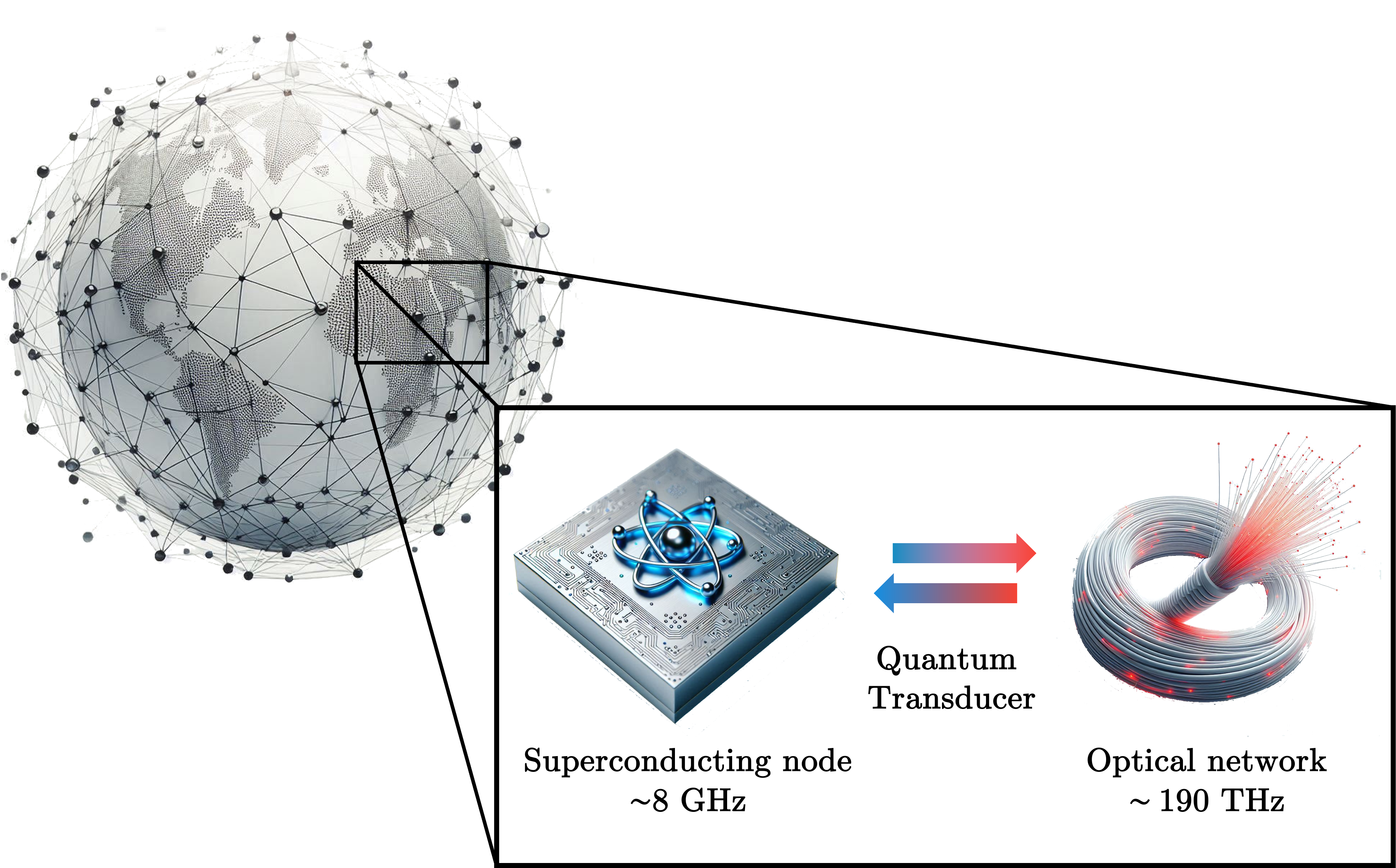
The complementary features of the aforementioned qubit hardware-platforms make them ideal candidates to fulfil the DiVincenzo criteria for quantum computing and communication [12], for fully unleashing the ultimate vision of the quantum revolution represented by the Quantum Internet. But, at the same time, these complementary features call for an inherent heterogeneity within a quantum network, where quantum states are processed by superconducting nodes and transmitted via flying qubits through optical quantum channels, as schematically depicted in Figure 1.
In order to embrace and sustain such a heterogeneity within a quantum network, quantum transduction is needed [2, 4]. More into details, quantum transduction is the process of converting one type of qubit to another, thus making possible the interaction between superconducting and photonic hardware technologies, which unfortunately operate at extremely different energy scales [6]. Accordingly, a Quantum Transducer (QT) – i. e. a network component performing quantum transduction – plays a crucial role in any quantum network, by constituting a matter-flying interface capable of integrating different qubits platforms [13, 6, 14, 15, 16].
Numerous challenges encompass both the hardware realization of a quantum transducer as well as the network architectures required to integrate it, making these topics very active areas of research.
I-A Outline and contribution
In the last decade, the field of quantum transduction has advanced significantly from a hardware standpoint [6, 17, 18]. The physics and hardware-engineering communities have been active in investigating schemes and technologies enabling such an interface, with multiple solutions.
In this context, the aim of this paper is to model quantum transduction from a complementary yet fundamental perspective, namely, from the communication engineering perspective. To this aim, we introduce and analyse different transducer strategies, by translating the quantum transduction process into a proper functional block within the quantum communication model. This analysis reveals that the transducer plays the functionality of adapting the quantum source output to the transmission channel at the source side, while at the receiver side it implements the opposite functionality. Thus, by resorting to a classical communication terminology, the transducer functionality is reminiscent of the modulator (transmission side) and de-modulator (receiver side) functional blocks within the classical communication system model [19].
Counter-intuitively, while in the classical world there exists only one scheme for implementing modulation/demodulation – namely, direct modulation – in a quantum network, direct modulation is one possibility, indeed, not even the most promising one due to the state-of-the-art limitations of transducer hardware.
Stemming from the above considerations, the aim of this paper is to drive the reader, with a tutorial approach, to grasp the fundamental research challenges underlying quantum transduction within the communication engineering domain. To the best of authors’ knowledge, a tutorial of this type is the first of its own.
The paper is structured as depicted in Figure 2.
Specifically, in Section II, we introduce and detail the core challenge for enabling the interaction between the different considered hardware-platforms, namely, the significant frequency gap between microwave and optical quantum carriers. In this same section, we describe how quantum transduction can operate either on quantum-information carrier or on entanglement carrier for entanglement generation and distribution111We suggest an unfamiliar reader to read the Boxes named Entanglement and Quantum Teleportation to grasp the importance of entanglement as a communication resource, before delving into the field of transduction acting on entanglement carrier.. Finally, we show that the same hardware device used for transduction of quantum-information or entanglement carriers – namely, for the so-called direct transduction – can be remarkably used as an entanglement source. This allows us to distinguish222It is worthwhile to note that the jargon direct quantum transduction is mainly limited by the literature to the process of transducing quantum information carrier [17, 20], whereas in the following we extend its use to the transduction of entanglement carrier, being entanglement the fundamental resource of quantum networks [21]. Furthermore, in the same works, EGT coupled with quantum teleportation is also referred to as Entanglement-Based Quantum Transduction (EQT). between Direct Quantum Transduction (DQT) and Entanglement Generation Transduction (EGT).
In Section III, we unpacks the specifics of DQT, by discussing individually the two cases: the conversion of a quantum-information carrier (i.e., of a qubit) in Section III-A and the conversion of an entanglement carrier (i.e., of an ebit) in Section III-B, respectively. This section is enriched with an in-depth analysis of the performance of DQT in terms of the key performance indicator from a communication engineering perspective, the quantum channel capacity, by taking into account the current state-of-the-art of transducer hardware. Through this analysis, we are able to highlight the reasons for which DQT acting on ebits is preferable with respect to DQT acting on informational qubits.
In Section IV we delve into the details of EGT, by introducing and discussing the ability of the transducer hardware to enable entanglement generation between the microwave and the optical domains. Specifically, we present two different physical interactions that can be exploited for entanglement generation: the two-mode squeezing interaction in Section IV-A and the beam splitter interaction in Section IV-B, respectively.
Then, stemming on the material presented so far, in Section V we provide some guidelines for elucidating and analysing how transduction is exploited for quantum information transmission. Specifically, we deepen different source-destination link archetypes, by exploiting different QT techniques. Our objective is to configure QT into network architecture considerations for a more comprehensive overview.
In Section VI, we introduce the transducer within a communication system model, designing it as a modulator/demodulator block.
II Quantum Transduction: Bridging the Frequency Gap
The main challenge underlining the interaction between superconducting and photonic quantum technologies lies in the huge gap between their operating frequencies. Indeed, flying qubits working at optical frequencies (typically about hundreds of terahertz) cannot directly interact with superconducting qubits that, conversely, work at microwave frequencies (typically few GHz). Therefore, a quantum transducer is needed to convert the state of a superconducting qubit into the state of a flying qubit and vice-versa, by bridging the five-order frequency gap between microwave and optical frequencies and, at the same time, by preserving the quantum state from one form to another.
![[Uncaptioned image]](https://cdn.awesomepapers.org/papers/8d26affe-7654-4f32-8b71-b9ae38bc7516/Tab.01.png)
It must be noted that there exist different physical channels for transmitting flying qubits, ranging from free-space optical channels to optical fibers. As a result, the transducer should be designed by taking into account the peculiarities of the physical channel the flying qubits propagate through [1].
It must be noted, though, that quantum transduction is not just a merely frequency conversion process, but many factors concur to it, as deeply discussed in Section VII.
Here, we introduce one first key aspect that characterizes quantum transduction: the “nature” of the carrier undergoing transduction. Similarly to classical transduction, a quantum transducer can in fact operate on a quantum information carrier, such as a qubit, as shown in Table I. But, differently from classical transduction, a quantum transducer can operate on an entanglement carrier, namely, a carrier of entanglement encoding quantum correlation rather than quantum information such as an entanglement bit (ebit)333In the following, EPR pair and EPR are used equivalently to denote a pair of maximally entangled qubits, and each qubit of the pair (with a slight abuse of notation, though, given than ebit is a unit of measure for entanglement) is referred to as ebit., as shown in Table I. In other words, a quantum transducer can operate either as frequency converter for an information carrier or as entanglement distributor for an entanglement resource [24], i.e., an interface to transfer entanglement resources from one hardware platform to another.
But there exists a second key aspect characterizing quantum transduction and summarized again in Table I: whether the hardware is used to transduce a carrier (as discussed above) or to directly generate hybrid entanglement, i.e. entanglement between the microwave and the optical domain. The two different operation-modes are thus referred to as Direct Quantum Transduction (DQT) and Entanglement Generation Transduction (EGT), respectively.
It is worthwhile to note that the difference between the two transduction-modes of DQT – quantum information carrier vs entanglement carrier – as well as the overall difference between the two operational-modes – DTQ vs EGT – are very far from being only conceptual. Rather, they have profound impact from a communication engineering perspective, as summarized in Table I and deeply discussed in Sections III and V, respectively.
III Direct Quantum Transduction
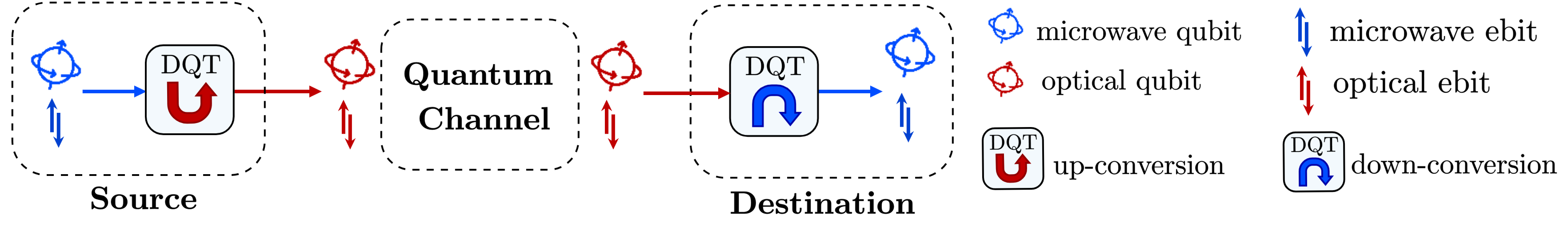
As introduced, DQT coherently converts superconducting qubits/ebits to flying qubits/ebits and vice versa, by allowing the transmission of quantum information and entanglement resources among distant quantum nodes [14].
By looking at a source-destination link, two transduction steps are required [27], as represented in Fig. 3:
-
-
up-conversion: converting the state of a superconducting qubit/ebit operating at microwave frequency into a degree of freedom of an optical photon operating at frequency .
-
-
down-conversion: converting the state of a photonic qubit/ebit, operating at optical frequency , into the state of a superconducting qubit/ebit, operating at microwave frequency .
However, there exists a non-zero probability that either or both the conversions fail, with failure-probability values strictly depending on the particulars of the hardware used for implementing the microwave-optical transduction. Among them, the conversion efficiency plays a key role as discussed in Sec. III-C. Other factors such as added noise, conversion bandwidth, and mode-shape mismatch also affect the failure probability, as discussed in Sec. VII. In literature, on one hand, the highest achieved conversion efficiency is about 50%, by using bulk optomechanical transducers [28, 29]. On the other hand, bulk electro-optical transducers have achieved slightly lower efficiency 10% [30], but with much lower added noise (). This allowed the demonstration of microwave-optical photon entanglement [31]. Integrated transducers [32, 33, 34, 35, 36, 37, 38, 39, 40] can offer more compact device footprint and high scalability, but the efficiency so far is limited to up to a few percent, mostly due to the lower power handling capabilities. Great efforts are being actively put on designing and improving the experimental devices. However, despite a huge progress has been made in the past decades, preserving the quantum states during conversions is still hard to reach with the state-of-the-art technology [41].
III-A Direct Transduction on informational qubit
DQT acting on an informational qubit is not a trivial process, since it should be able to preserve the encoded quantum information [42]. To this aim, it is necessary that the quantum information is preserved through both the transmission on the quantum channel and during the up- and down-conversion processes. However, if the qubit is lost during the transmission due to the channel attenuation or is corrupted by noise, the associated quantum information cannot be recovered by a measurement process or by re-transmitting a copy of the original information, due to the quantum measurement postulate and the No-Cloning Theorem [24]. Accordingly, by taking into account both the impairments induced by the channel transmission and the failure probability of conversion processes, we conclude that DQT on informational qubits is not yet a viable strategy for the today technology.
III-B Direct Transduction on ebits
By considering the limitations of DQT on informational qubits, an alternative approach is to apply up- and down-conversions on the entanglement resource itself, i.e. on the ebits. With this strategy the impact of noisy quantum transduction and noisy optical propagation shifts from quantum information to entanglement resource. Thus, its main advantage lies in the possibility of entanglement to be regenerated. Indeed, differently from informational qubits, entanglement, being a communication resource rather than information, is not constrained by the no-cloning theorem [22]. Thus, even if the ebit carrying quantum correlation is lost during the channel transmission or the transduction conversion failure, it can be regenerated without restrictions, until the conversions succeed and the entanglement is correctly distributed between the remote nodes. Once the entanglement distribution is successful, an informational qubit can then be “transmitted” via quantum teleportation. This allows to overcome the stringent requirements of DQT on quantum information. The main differences between DQT on quantum information and on ebits are summarized in Tab. I.
III-C Hardware limitations of DQT
| Symbol | Hardware Parameter |
| microwave frequency | |
| optical frequency | |
| optical pump frequency | |
| conversion efficiency | |
| cooperativity | |
| extraction ratio of mode | |
| total dissipation rate | |
| external coupling rates of mode | |
| single-photon electro-coupling rate | |
| pump photon number |
To implement both up- and down- conversions, an input laser pump is required to initiate the conversion of the photon associated to the qubit/ebit to be converted.
The conversion of the input photon into the output photon at the desired frequency can be performed through one or more intermediate steps, such as mechanics [28, 29, 33, 34, 38] or magnonics [43, 44], depending on the transducer hardware. A direct conversion between microwave and optical frequencies is instead realized through electro-optic transducers [45, 46, 35, 47, 36, 30, 31], which reduce device complexity and avoid intermediate noise sources. The trade-off though is the weaker nonlinearity compared with optomechanical schemes.
For the sake of clarity, in this paper we focus on electro-optic quantum transducers, but developed the theoretical analysis can be easily extended to different transduction hardware, by properly accounting for the particulars of the hardware parameters444See as instance the conversion efficiency (eq. 6) in [17] for electro-optomechanical transducers.. In a nutshell, electro-optic transducers implement the transduction process by exploiting an input pump laser that initialize the Pockels effect [45, 46] to create a beam splitter interaction between optical and microwave signals. Schematically, an input laser pump at frequency interacts with an input photon at microwave frequency frequency (at optical frequency ) to produce an optical photon at (a microwave photon at ).
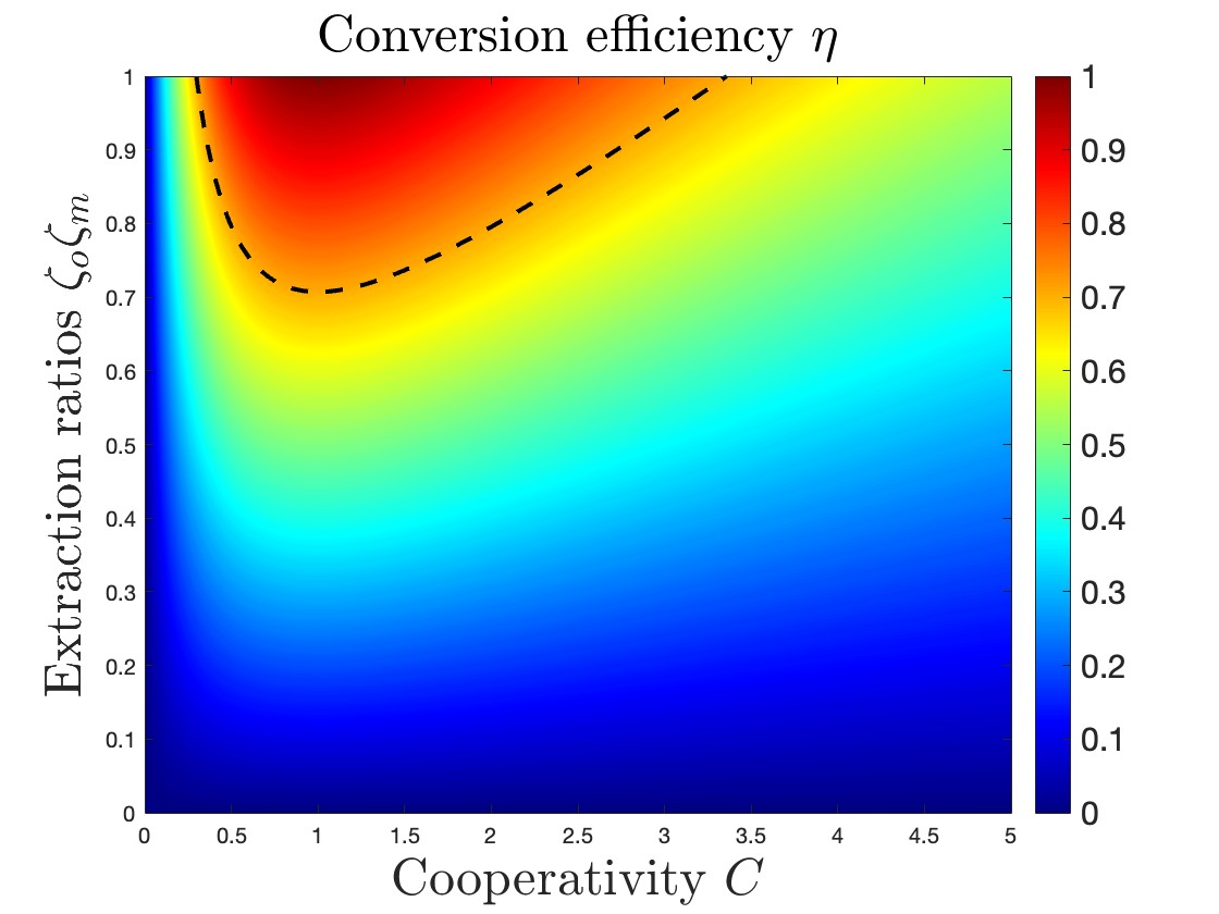
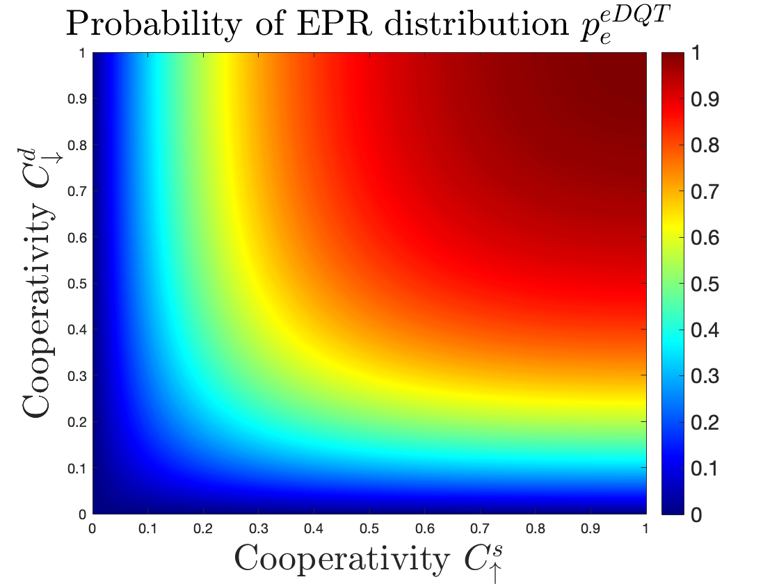
The main parameter governing electro-optic transduction is the conversion efficiency , which is the probability of successful conversion. In the resolved-sideband limit where undesired amplification is negligible, the system is reciprocal and the efficiency is the same for up- and down- conversions. Under resonant conditions, the efficiency can be expressed as [46, 17]:
| (3) |
In (3), denotes the so-called extraction ratio of mode 555We denote optical mode with subscript whereas microwave mode with subscript ., given by the ration between the external coupling rates and the total dissipation rates: [17], and denotes cooperativity, related to the interaction of microwave and optical field within the transducer, defined as [46, 17]:
| (4) |
In (3), denotes the single-photon electro-coupling rate and is the pump photon number. It’s worth pointing out that the added noise, in general, can be different for different conversion directions, depending on how the noise sources couple to the conversion process. Detailed analysis of added noise can be found in Ref. [17]. In the following texts, we use and to denote the efficiencies of up- and down- conversion, respectively. We choose this notation to enhance clarity of the paper, even though the formulation of the conversion efficiency, in terms of dependence on the transducer parameters, remains unchanged for both conversion directions. The main transducer parameters are summarized in Tab. II.
By accounting for eq. 3, it follows that high conversion efficiency requires both cooperativity and extraction ratios close to 1. This is clearly depicted in Fig. 4, which shows as a function of , and the product of the extraction ratios . However, reaching high values of both these parameters is still an open and crucial challenge. Indeed, while there is a wide-scientific consensus in considering unitary values for feasible to achieve in the near-future666Typical values assumed in theoretical studies are around [48], whereas experimental values in the order of have already been measured [47]., experimentally measured values for only recently reached . Therefore, the cooperativity parameter constitutes the bottleneck of the transducer electro-optical efficiency.
Since the conversion efficiency is the probability of having a successful conversion, low values of , in turn, affect also the achievable quantum channel capacity. In other words, for having a non-zero quantum capacity, stringent conditions on should hold [48, 20]. These conditions change whether DQT occurs on the informational qubit or on the ebit.
More into details, the cascade of up-conversion, quantum channel and down-conversion, in point-to-point communication link leveraging DQT on informational qubits, can be modeled as an overall equivalent quantum erasure channel. Accordingly and as highlighted in [49], the one-way quantum capacity is the right metric to adopt for capturing the communication performance. As proved in [2], by neglecting the length effects of the fiber connecting the source and the destination, assuring a unitary capacity requires unitary cooperativity for both the up- and the down- conversions. Yet, such a value, as aforementioned, exceeds current state-of-the-art technologies. By relaxing the hypothesis of unitary capacity, i.e., by requiring only a non-null one-way quantum capacity, the up- and down efficiencies should satisfy the condition . By accounting for eq. (3), this, in turn, implies that the cooperativity should approximately satisfy [2]. In Fig. 4, the efficiency values enabling non-null one-way quantum capacity are highlighted with the dotted black curve.
Similarly, when in a point-to-point communication link, DQT acts on ebits, the cascade of up-conversion, fiber channel and down-conversion can be still modelled as an equivalent quantum erasure channel [4]. However, in such a case [20, 42], the two-way quantum capacity [49] should be considered as performance metric rather than the one-way capacity. In fact, the ebits of the EPR pairs – distributed for eventually teleporting the informational qubit to the destination – can be regenerated and re-distributed in case of losses, without affecting the informational qubit. Thus, for assuring a no-null two-way quantum capacity, the up- and down efficiencies should satisfy the condition: . In a nutshell, the key advantage of DQT applied on ebits with respect to DQT on informational qubits is the less stringent requirement on the transducer hardware parameters for assuring a no-null quantum capacity. We will delve deeper on this in Sec. V-D.
IV Entanglement generation Transduction

As mentioned in Sec. II, in EGT, it is possible to generate hybrid microwave-optical entanglement [31, 40].
Specifically, transducer can generate entanglement with two different electro-optic interaction: two-mode squeezing or beam-splitter interaction as shown in Fig. 5 and explained in the next sections.
IV-A EGT through two-mode sequeezing interaction
In the case of EGT via two-mode squeezing interaction, the input pump, exciting the transducer, drives a spontaneous parametric down-conversion (SPDC), which generates entanglement between optical and microwave fields [48, 50, 51, 27]. Specifically, entanglement is generated whenever the quantum transducer is initialized with no input microwave photon, as depicted in Fig. 5, and the input pump frequency is set to the sum of the frequencies of the optical and microwave photons, i.e., , (aka “blue detuning”). Ideally, the output state can be expressed with Fock state notation as[51, 27, 52]:
| (5) |
with the subscripts and denoting the photon domain, i.e., microwave or optical. Accordingly, in Eq. (5) the term denotes the generation of both microwave and optical photons, and the term denotes no photon generation [53]. The coefficients and depend on the hardware parameters as the effective squeezing factor [51] and the cooperativity parameter . It is important to note that Eq.(5) assumes that the generation of higher order photon pairs is negligible, which is a good approximation in the low power regime. In general, the SPDC produces a two-mode squeezed vacuum that gives continuous-variable entanglement [53].
IV-B EGT through beam splitter interaction
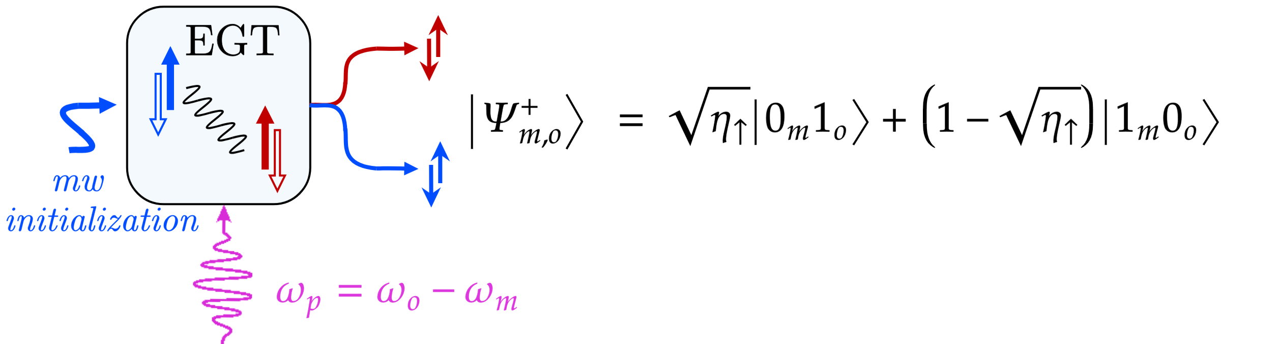
The assumption of neglecting the generation of higher order photon pairs in EGT with two-mode squeezing interaction is satisfied without any restriction in case of exploiting beam splitter interaction for entanglement generation. In this case the transducer requires a specific initialization of a microwave photon inside the cavity [27], as schematically depicted in Fig. 5, and the input pump field is set to operate on a frequency that is the difference of the frequencies of the optical and microwave photons, i.e. . This leads to an entangled state in the form[2]:
| (6) |
where the term denotes that the microwave photon of the initizalization was converted into an optical one and the term denotes that the microwave photon was not converted. Specifically, if the transducer conversion efficiency is the state in eq. (6) becomes [2]:
| (7) |
that constitutes a Bell State between different frequency domains.
Remark.
The assumption of obtaining an EPR state in the form of eq. (7) depends on a careful setting of the transduction hardware parameters [27]. In this paper we only consider the effect of the conversion efficiency on the purity of the generated state, as in eq. (6), but other noise source and hardware parameters must be take into account to obtain the ideal state of eq. (7). Any hardware mismatch from the ideal setting would impact on the purity of the generated entangled pair.
It is important to notice that the beam splitter interaction exploited in EGT is the same interaction exploited in DQT for frequency conversions (up- and down-) presented in Sec. III. The main differences between the beam splitter interaction exploited for DQT and EGT lie in two key points. First, the photon to be converted in the DQT is the informational qubit, we aim to transmit, or the ebit of the EPR pair, we aim to distribute. Therefore, these quantum states have to be preserved in the conversion. In contrast, in the EGT, the entanglement is generated in the so-called path-entanglement [54, 55, 56]. Thus, the preservation of the quantum states is not of concern.
The second key point is that, while low values of the efficiency imply higher conversion-failure probability in the DQT (either for informational qubit or ebit), in EGT low values of the efficiency do not imply a failure of the process, as evident from (6). Indeed, determines how much the generated entangled state deviates from being a maximally entangled one. According to this last consideration, the great advantage of the EGT over DQT is therefore related to the hardware limitations itself. In other words, while the quality of DQT is strictly related to high values of conversion efficiency, the EGT process can generate entanglement with values of that are reachable with current state-of-the-art technology. The main differences between DQT and EGT are summarized in Tab. I.
Remark.
It is worthwhile to note that in EGT with beam splitter interaction the role played by the microwave initialization at hardware level is reminiscent of a basis change. Indeed, (5) and (6) are equivalent quantum states up-to a basis change. This consideration allows us to use interchangeably the two EGT interactions, since they produce LOCC-equivalent states, from a communication perspective.
V Source-Destination Link Archetypes
The analysis developed in the previous sections is not sufficient for grasping all the implications of QT on the design of a quantum network. Indeed, it is fundamental to configure QT into network architecture considerations, for a more comprehensive overview.
For the reasons highlighted in Sec. III, DQT on informational qubits is still beyond the state-of-the-art technologies, due to the stringent requirements in terms of high efficiency () and low added noise (). As a result, in the following, we focus only on the possibility to share quantum information among the network nodes via teleporting. Since quantum teleportation requires a pre-shared EPR pair between source and destination, we contextualize quantum transduction for entanglement generation and/or distribution. Thus, in the next subsections we present different source-destination link archetypes leveraging both DQT on ebits and EGT.
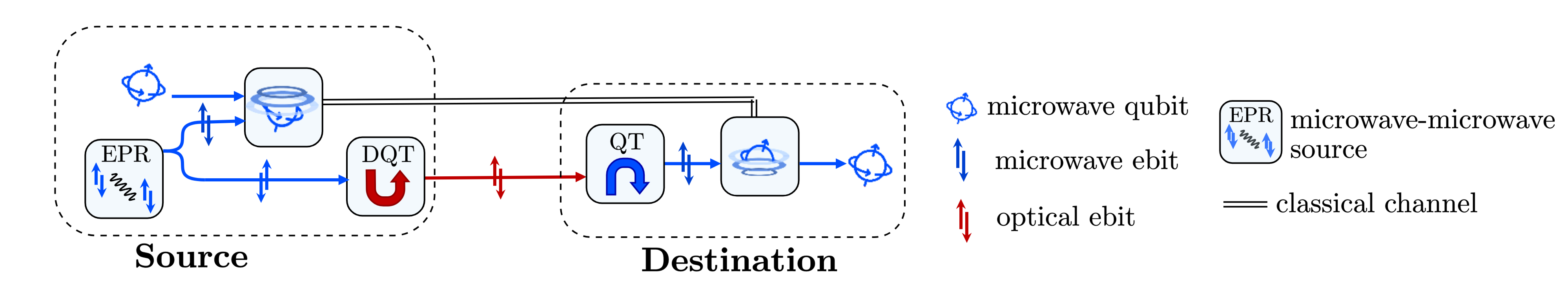
V-A e-DQT
The first archetype we consider is a source-destination link, where entanglement distribution exploits two DQTs, as depicted in Fig. 6(a). For the sake of clarity, we assume that the entangled state, to be distributed, is an EPR pair. The state is locally generated at the source at microwave frequencies, which can be expressed in the Fock-state notation as [57]:
| (8) |
with the superscript denotes the “location” of the photons, i.e., at the source. The EPR is then distributed with a sequence of up- and down-conversions. Specifically, one microwave photon is up-converted at the source, sent over a fiber channel, and down-converted at the destination. If both the conversions are successful, the resulting EPR state shared between the source and the destination is:
| (9) |
where the superscript denoting the “location” of the photons at the destination. Once the EPR is distributed the teleportation protocol can be performed.
As mentioned in Sec. III, if one or both conversions fail, the entanglement generation and distribution process can be re-executed again until the distribution is successful. Moreover, it is important to empathize that the informational qubit is not involved in the transduction process, but only in the local operations and classical communications (LOCC) [1] required by the quantum teleportation protocol. This, in turn, implies that the noise introduced by DQT impacts on the quantum state to be transmitted.
In Sec. V-E, we generalize the described e-DQT archetype, by removing the hypothesis of entanglement generated at the source.
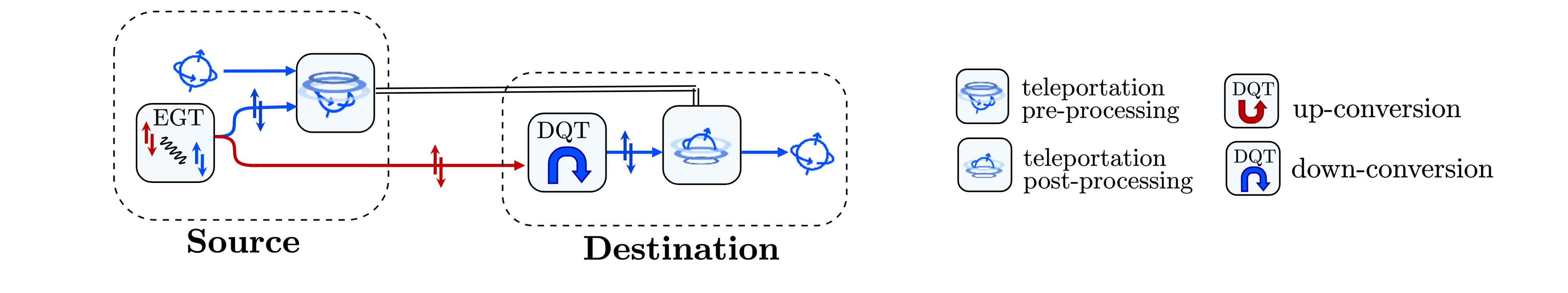
V-B EGT Coupled with DQT
In this section, we present a second archetype for a source-destination link, exploiting EGT, as depicted in Fig. 6(b). This archetype allows to reduce the number of direct conversions for distributing entanglement between source and destination, with respect to the e-DQT archetype.
Specifically, a transducer located at the source generates hybrid entanglement, by exploiting one of the two physical interactions described in Sec. IV-A and Sec. IV-B. For the sake of clairty, by assuming a beam spitter interaction and a conversion efficiency of , a Fock state in the form of eq. (7) is generated. The optical photon of the generated entangled pair is then transmitted to the destination through an optical fiber and down-converted to the microwave domain therein. The resulting shared between the source and the destination can be expressed as follows:
| (10) |
The teleportation protocol can now be applied to transfer the quantum information.
In this archetype, the entanglement distribution process requires that the destination is equipped with a quantum transducer capable of down-converting from optical to microwave one ebit of the generated hybrid entangled state. Thus, the strategy still suffers from the inefficiency of direct quantum transduction – although limited to a single conversion (optical to microwave) rather than both up- and down-conversions.
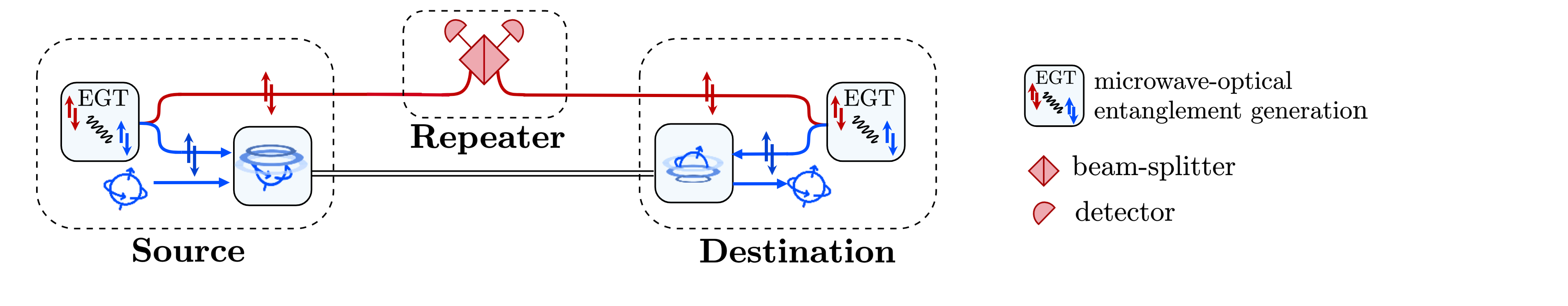
V-C EGT Coupled with Swapping
A third source-destination link archetype exploits EGT coupled with entanglement swapping777Entanglement swapping[65] is a strategy which extends the entanglement distribution distance. The reader may refer to the vast literature on the subject. , as depicted in Fig. 6(c).
Specifically, with two EGT at the source and destination side, two hybrid EPR states, in the form of eq. (7), are generated. Accordingly, the entanglement generation occurs “at both points” rather than at “source only” [24, 21].
The optical ebits of both the generated entangled states are then transmitted through optical fibers, by reaching a beam splitter followed by two detectors. The overall setup is unable to distinguishing the which-path information [27, 66, 67]. A click of one of the two detectors denotes the presence of an optical photon. However, due to the path-erasure – i.e., the impossibility of knowing whether the optical photon responsible for the detector-click has been generated at the source or at the destination – it is impossible to distinguish where the entanglement generation process has taken place (namely, whether at the source or at the destination), and thus it is impossible to distinguish whether a microwave photon is present at source or at destination. This results into the generation of another form of path-entanglement [68] between the microwave photons at the source and at the destination, in the form of (10). Basically, the famous Duan–Lukin–Cirac–Zoller protocol is performed [69].Thus, the overall effect of beam splitter and detectors is reminiscent of entanglement swapping, projecting the received optical photons into a Bell state.
The distributed microwave-microwave entanglement can now be exploited to transmit quantum information, through quantum teleportation.
It is worthwhile to highlight that a detector click does not always correspond to an EPR shared between source and destination. Indeed, while the purity of the hybrid generated EPR depends exclusively on the transducer hardware, as discussed in Sec. IV-B, the purity of heralded microwave EPR expressed in (10) depends also on the characteristics of the repeater node, i.e. on the beam splitter and optical detectors characteristics. Specifically, there exists the possibility that more than one photon reach the repeater node. In fact, when both the transducers generate optical photons, only one detector click is triggered due to path erasure. In such a case, a detector click corresponds to the presence of two microwave photons, one at the source and one at the destination. Hence, the state shared between the remote nodes is , which is definitely not an entangled state as in (10). However, if we reasonably assume the availability of photon-number-resolved detectors (PNRD), then it is possible to distinguish the event of receiving two optical photons – one for each transducer in each link – from the event where only one optical photon is received. And the double-photon event can be discarded in favour of a new distribution attempt.
It must be acknowledged that the key advantage of the archetype “EGT coupled with swapping” lies in the possibility of heralding entanglement via off-the-shelf hardware – i.e., via PNRD. Specifically, a detector click for each transduction attempt constitutes an indicator for identifying the generation of entanglement between the source and the destination, without destroying it. In the previous two archetypes, i.e. e-DQT (Sec. V-A) and EGT coupled with e-DQT (Sec. V-B), there exists the possibility of heralding entanglement, by exploiting another degree of freedom, different from the one for entanglement encoding.
For instance, time-bin entanglement of microwave photons have been experimentally demonstrated [70]. Also time bin of hybrid entanglement generated within a traducer (EGT) have been measured [53, 40]. These examples not only exploit two different degree of freedom (one for entanglement generation and the other for entanglement heralding), but also imply the introduction of additional hardware setups for the heralding. On the contrary, in EGT coupled with swapping, the entanglement heralding is embedded in the setup itself and, for this reason, it is not necessary to exploit other degree of freedom and/or to introduce any additional heralding equipment.
![[Uncaptioned image]](https://cdn.awesomepapers.org/papers/8d26affe-7654-4f32-8b71-b9ae38bc7516/Tab.03.png)
![[Uncaptioned image]](https://cdn.awesomepapers.org/papers/8d26affe-7654-4f32-8b71-b9ae38bc7516/tabsymbol3.png) denotes the EPR that has to be distributed.
denotes the EPR that has to be distributed. ![[Uncaptioned image]](https://cdn.awesomepapers.org/papers/8d26affe-7654-4f32-8b71-b9ae38bc7516/tabsymbol1.png) and
and ![[Uncaptioned image]](https://cdn.awesomepapers.org/papers/8d26affe-7654-4f32-8b71-b9ae38bc7516/tabsymbol2.png) represent DQT, up- and down-conversion respectively.
represent DQT, up- and down-conversion respectively. ![[Uncaptioned image]](https://cdn.awesomepapers.org/papers/8d26affe-7654-4f32-8b71-b9ae38bc7516/egt.png) represents the EGT.
represents the EGT.V-D Archetype Comparison
Stemming from the above described archetypes, here we conduct a performance comparison among them, by analysing some key communication metrics as functions of the main transducer-hardware parameters. Specifically, our analysis bridges the gap between different hardware platforms for quantum transducers, such as electro-optic and opto-mechanical systems. Indeed, by focusing on common characteristics shared by all transducer implementations, such as conversion efficiency, we establish communication metrics that are agnostic to specific hardware configuration. The key metric we define is the probability of successfully distributing an EPR from the source to the destination888For the theoretical details about the closed-form expressions of the success ebit distribution and for the achievable quantum capacity for all the three archetypes, we refer the reader to the appendices in [4]. [4].
For the e-DQT archetype, , as a function of transducer parameters, can be expressed as follows [4]:
| (11) |
where the superscripts and destination denote the “location” of the transducer process, i.e., at source and at destination side. In Eq. (11) the term takes into account the fiber losses, with denoting the length of the fiber link between source and destination and denoting the attenuation length of the fiber999As for today, commercial fibers feature an attenuation lower than db/km. As instance, optical photons with wavelength equal to nm – i.e., DWDM ITU GHz channel number in the C band – experience an attenuation of dB/km, which corresponds to km. [71]..
It is evident that in case of noiseless quantum teleportation, i.e, under the hypothesis of noise-free LOCC, can be seen as the probability of successful transmission of quantum information as well. Therefore, the probabilities of successfully transmitting quantum information and successfully distributing entanglement become equivalent. In other words, the two-way quantum capacity coincides with .
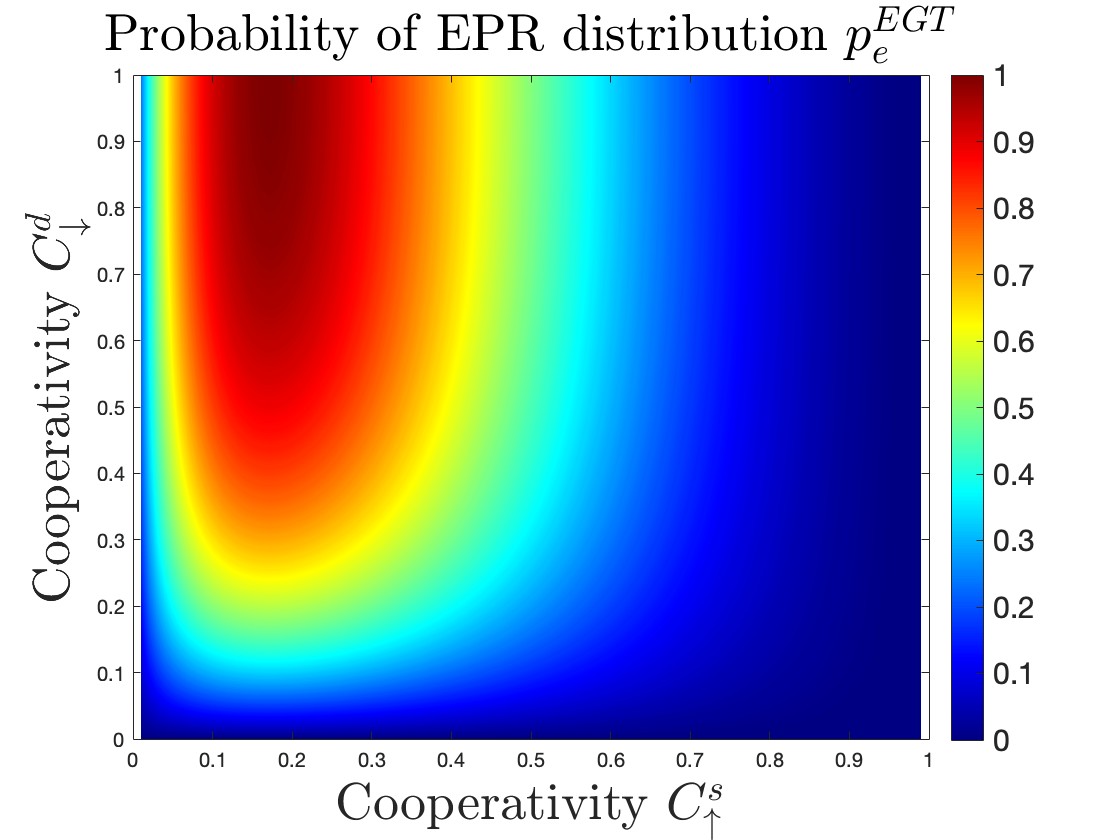
For the “EGT coupled with e-DQT” archetype, the probability of successfully distributing an EPR pair is:
| (12) |
where 101010With a small abuse of notation, we have indicated in the argument of the Von Neuman entropy the eigenvalue determining its value rather than – as usually done – the density matrix on which the entropy is evaluated. denotes the Von Neuman entropy given by:
| (13) |
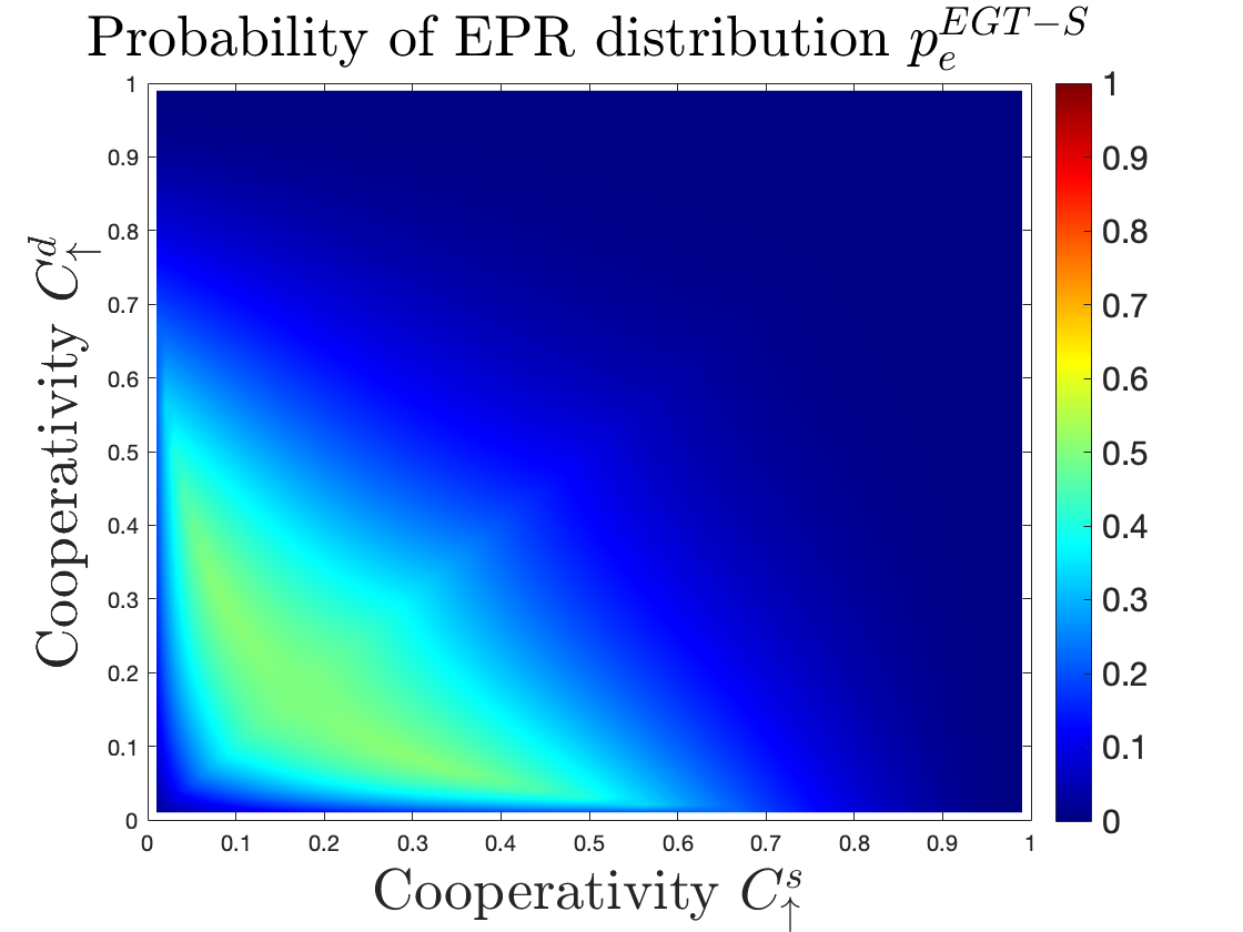
Finally, for the “EGT coupled with Swapping” archetype, the probability of successfully distributing an EPR is given by [4]:
| (14) |
where denotes the efficiency between and that minimizes .
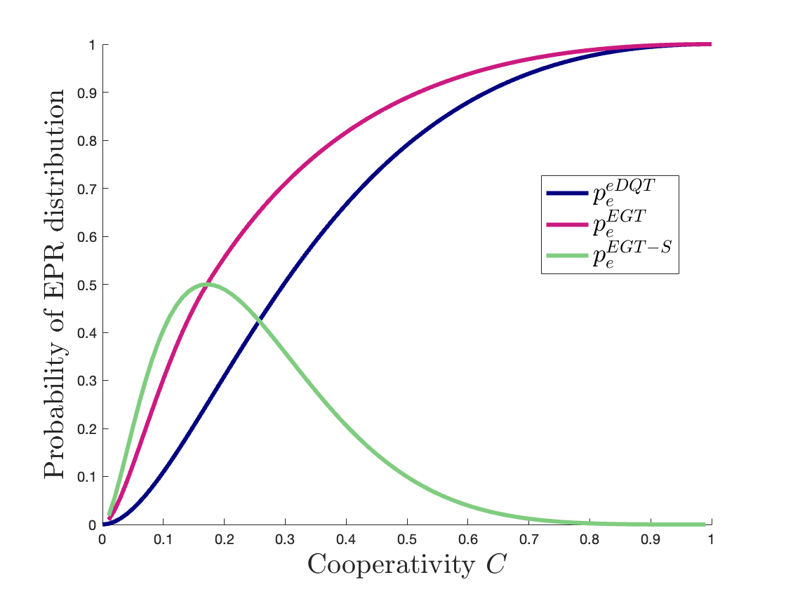
Fig. 7 shows the probability of successful EPR distribution for the three considered archetypes, as function of the cooperativity , namely, as discussed in Sec. III-C, the main hardware parameter limiting the transducer performances. Similarly to what was done with , also for we indicate with the subscripts and the direction of the conversion (up or down) and with the superscripts and the location of the transduction (source and destination).
We note that for the e-DQT archetype, the presence of two e-DQT processes requires unitary values for both and in order to obtain (equivalently unitary two-way quantum capacity), as shown in Fig. LABEL:fig:07.1. This restriction can be relaxed in the case of EGT coupled with e-DQT. In fact, in this type of archetype, to obtain a unitary , the value of strictly equal to 1 is required only for the transducer at the destination (=1), responsible for the direct conversion, while has to satisfy , as shown in Fig. LABEL:fig:07.2.
Finally, in EGT coupled with swapping, no direct conversion is required. Therefore, the maximum amount of can be achieved with , as shown Fig. LABEL:fig:07.3. Thus, this archetype determines an improvement in terms of minimum cooperativity that allows a non-zero entanglement distribution probability. But, this comes at the cost of a probability that never reaches . This, in turn, implies that the two-way quantum capacity does not reach one as well.
To further highlight the comparison between the performances of the different proposed archetypes, Fig. 8 presents the three as function of within the same plot111111Here, for EGT coupled with e-DQT, is .. It is evident that in archetypes exploiting hybrid entanglement generation transducers, it is possible to relax the constraints on the required hardware parameters, for reaching selected probability values (aka, both unitary cooperativity at source and destination). Therefore, the presence of a DQT acts as a bottleneck, limiting the overall performances of the system.
V-E Additional Source-Destination Link Archetypes
The analysis developed in the previous subsections is not exhaustive. Indeed, additional source-destination link archetypes can be considered, accordingly to i) the entanglement generation “location” and ii) the entanglement type.
More in detail, with reference to the “location”, the entanglement generator can be at source, at the middle or at both points [24, 21]. Instead, regarding the type, it is possible to distinguish archetypes whether the entanglement resource is generated within (aka EGT deeply described in Sec. IV) or outside the transducer, through an external entanglement source. In literature, it is common to refer to these two types of entanglement generation as intrinsic and extrinsic process [42], respectively.
Tab. III summarizes the possible source-destination link archetypes, accordingly to the “location”, frequencies and type of entanglement, by including also the archetypes discussed in the previous subsections. Teleportation process for quantum information transmission is not explicitly depicted to make the figures clearer. As done before, blue and red symbols refer to ebit at microwave and optical frequencies, respectively.
By observing the various possibilities, we can draw some considerations. First, it is worth to highlight that as the number of DQT processes increases, the risk of losing the entanglement increases accordingly. Indeed, any processing can only worsen entanglement. This directly implies that extrinsic entanglement generation at middle point requires at least two DQT processes that can scale up to four in the case of entanglement generated at microwave frequencies.
Additionally, we observe that it is meaningless to treat the generation of extrinsic optical entanglement at the “source”, since we are considering the network scenario where source and destination are superconducting nodes. Furthermore, the generation of extrinsic optical entanglement at “both point” introduces a communication scheme that differs from those introduced in [24, 21]. Indeed, the “both point” referred to are not source and destination nodes, but two external optical nodes, whose function is just to generate entanglement.
Clearly starting from the described source-destination link archetypes, it is possible to consider more complex network architectures, characterized by higher number of direct conversions or swapping nodes, accordingly to the specific network application and distance among the nodes.
VI Communication System Model
Stemming from the analysis developed in the previous sections, we are now ready to map a transducer into a functional block within a quantum communication system model.
More into details, a transducer plays a role reminiscent of the role played by a modulator at source side in a classical communication system model (a de-modulator at destination side), since it basically adapts the source output to the transmission channel (and vice versa at destination).
However, while in the classical world there exists only one approach for implementing modulation/demodulation, namely, direct modulation/demodulation, in a quantum network, direct modulation/demodulation is only one possibility. Indeed, in the quantum realm, we can distinguish between:
-
•
Direct Modulation/Demodulation,
-
•
Un-direct Modulation/Demodulation.
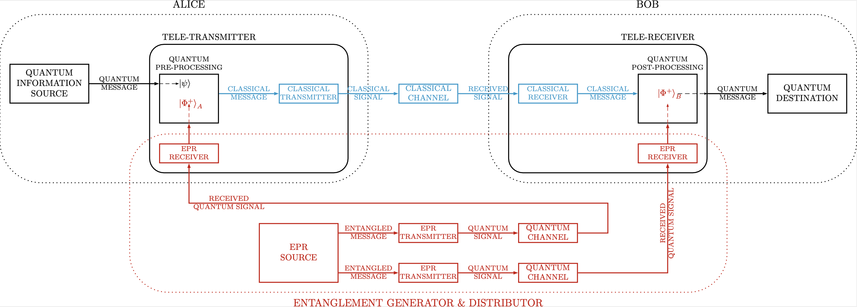
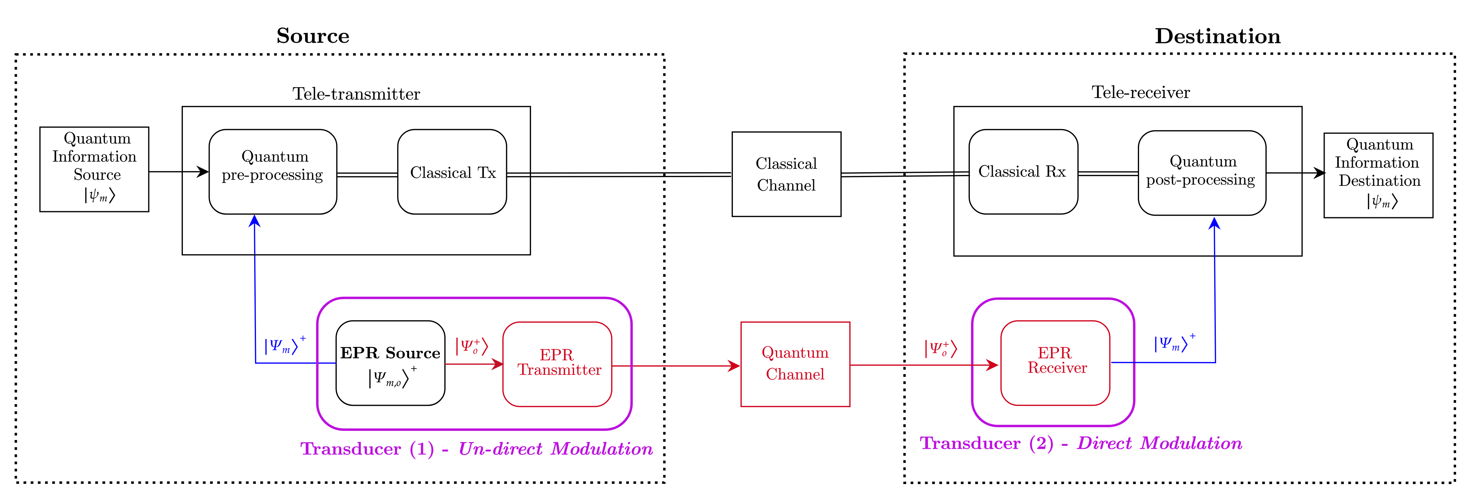
Direct Modulation/Demodulation refers to the functionality actually implemented by a DQT. In this sense, there exists a one-to-one mapping between a transducer and a modulator (demodulator) functional block within the classical Shannon communication system model [19]. The modulation/demodulation functionality of DQT can be performed on the informational qubit, as depicted in Fig. 3, or on the ebits, as in the source-destination link archetypes in Sec. V. For the reasons highlighted in Sec. III-C, we focus on the e-DQT for its communication performance. With this in mind and by elaborating further, we re-call the communication system model proposed in [24] and shown in Fig. 9 for quantum teleportation121212In Fig. 9 “Alice” and “Bob” refers to source and destination nodes, respectively..
By inspection, it is possible to infer that the model in Fig. 9 holds also for describing the source-destination archetype exploiting e-DQT, in case of entanglement generation at middle-point (see Tab. III). In particular, in this scheme, the modulator/demodulator functional block is included within the EPR Transmitter and Receiver blocks. And this functionality is implemented by the transducer.
On the other hand, Un-direct Modulation/Demodulation refers to the functionality implemented by EGT, which exploits the transduction process itself for generating entanglement. More into details, the EGT generates hybrid entanglement between microwave and optical modes. Thus, the optical generated ebit is already adapted to the quantum channel, while the microwave ebit remains at the source for being successively exploited for quantum teleportation. In the above sense, there is no need to adapt the generate ebits to the quantum transmission channel. And, thus, we refer to the functionality implemented by EGT as undirect modulation/demodulation. In a nutshell, with EGT the modulation process is “virtually” performed within the quantum transduction. For the above differentiation between e-DQT and EGT, we refer to the latter as second generation of transducers.
Accordingly, a one-to-one correspondence between quantum transducer functionality and the classical modulation/demodulation functional block is not established.
Stemming from the above considerations, we particularize in Fig. 10(a) the communication system model reported in Fig. 9 to the EGT Coupled DQT archetype, analysed in Sec.V-B. Specifically, the transducer at the source, that implements an EGT, performs an Un-direct modulation. While, at destination, the transducer, by performing a e-DQT, acts as an EPR demodulator, aka direct-demodulation.
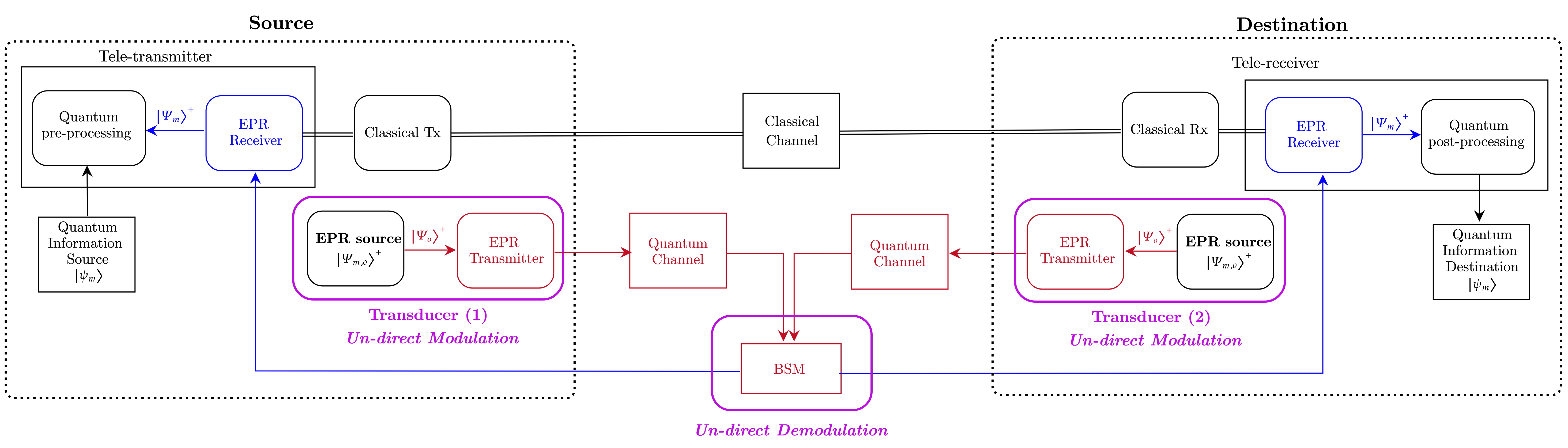
Let us now consider the case of EGT Coupled with Swapping of Fig. 6(c). The correspondent communication system model is schematically depicted in Fig. 10(b). In this case, both transducers at source and destination implement EGT performing Un-Direct Modulation.
It is worth to notice that in this scenario also the demodulation is performed “virtually”. Here, the demodulator block is not implemented by a transducer but by the BSM node, which, by generating optical path entanglement, distributes entanglement between superconducting non-interacting nodes.
This implies that, the process of “receiving” the ebits of the EPR is fulfilled without the physical reception of the particle by the source and the destination nodes. Indeed, the entanglement swapping distribute the EPR without physically transmitting the microwave ebit to source and destination nodes. Therefore the EPR Receiver blocks is “virtual”, since its functionality, i.e., the process of “receiving” the member of the entangled pair, is fulfilled without the physical reception of the particle [24].
VII Discussion
As mentioned in Sec. III-C, several factors concur to the transducer conversion efficiency and, consequently, to the communication performances of the considered strategies.
To elaborate more, quantum transduction is not just a merely frequency conversion process, since many parameters challenge the interfacing between different hardware platforms such as photonic and superconducting. Indeed, in order to achieve a good transduction, the physical modes of microwave and optical systems must be matched, which includes considerations of impedance, spatial overlap, and the temporal properties of the signals. This, as showed in [15], can be captured by the electro-optic coupling coefficient in equation (3). Another key parameter is the power of the laser pump that enables the interaction. This parameter is captured by the pump photon number parameter in (3). Indeed, increasing the pump power can easily boost the conversion efficiency. However, high levels of pump power, in turn, introduce thermal noise, differently from the utilization of low-power and pulsed laser pump [30]. Accordingly to the above, our choice of focusing on the conversion efficiency as the main characterizing parameter for quantum transduction has been key. In fact, this choice allowed us to abstract from the particulars of the specific technology underlying the transducer hardware. Consequently, the proposed analysis can be easily extended to different transducer hardware solutions, available in the state-of-the-art technology. And remarkably, this choice also allows us to track technological advancements by just adjusting a single parameter to incorporate the technological improvements.
VII-A Intra-band Transduction
In this work, we analysed microwave-optical transduction with the aim of interconnecting distant superconducting quantum nodes via optical quantum channels. However, as mentioned in Sec.I, there exist several qubit platforms. Among them, trapped ions[72, 73], quantum dots [74, 75, 76] and spin-qubits [77] directly interact with optical photons.
These qubit platforms emit entangled photons at visible/NIR wavelengths. Therefore, for long-distance entanglement distribution, it is necessary a frequency conversion to teleco frequencies. Indeed, O-band and C-band are commonly used for long-distance entanglement distribution [78, 79] with the ultimate goal of entanglement distribution on lit-fiber networks. [80, 81, 82]. This frequency conversion from optical to optical frequencies is referred to as intra-band transduction [17]. Therefore, also if some qubit platforms exploited for computation can spontaneously interact with optical photons, quantum transduction is inevitable for long-distance communications. And moreover, due to the intrinsically weak interactions between photons, a frequency converter for O- or C-band requires high power pump and coupling [17].
In a nutshell, quantum transduction is mandatory for quantum networks. We choose to focus on the transduction between microwave and optical domains, since at the time of the manuscript writing, superconducting technology constitutes the most promising platform for quantum computing. Indeed, superconducting quantum gates are fast [83] with high-fidelity levels [84], and their scalability allows to build quantum processors with hundreds of qubits [85].
References
- [1] A. S. Cacciapuoti, M. Caleffi, F. Tafuri, F. S. Cataliotti, S. Gherardini, and G. Bianchi, “Quantum internet: Networking challenges in distributed quantum computing,” IEEE Network, vol. 34, no. 1, pp. 137–143, 2020.
- [2] L. d’Avossa, A. S. Cacciapuoti, and M. Caleffi, “Quantum transduction models for multipartite entanglement distribution,” in 2024 International Conference on Quantum Communications, Networking, and Computing (QCNC), 2024, pp. 1–8.
- [3] L. d’Avossa, M. Caleffi, C. Wang, J. Illiano, S. Zorzetti, and A. S. Cacciapuoti, “Towards the quantum internet: Entanglement rate analysis of high-efficiency electro-optic transducer,” IEEE QCE 2023, 2023.
- [4] L. d’Avossa, A. S. Cacciapuoti, and M. Caleffi, “Modelling quantum transduction for multipartite entanglement distribution,” arXiv preprint arXiv: 2407.04015, 2024.
- [5] L. d’Avossa, C. Zhan, J. Chung, R. Kettimuthu, A. S. Cacciapuoti, and M. Caleffi, “Simulation of quantum transduction strategies for quantum networks,” arXiv preprint arXiv:2411.11377, 2024.
- [6] N. Lauk, N. Sinclair, S. Barzanjeh, J. Covey, M. Saffman, M. Spiropulu, and C. Simon, “Perspectives on quantum transduction,” Quantum Science and Technology, vol. 5, 02 2020.
- [7] G. Wendin, “Quantum information processing with superconducting circuits: a review,” Reports on Progress in Physics, vol. 80, no. 10, p. 106001, sep 2017.
- [8] H.-L. Huang, D. Wu, D. Fan, and X. Zhu, “Superconducting quantum computing: a review,” Science China Information Sciences, vol. 63, pp. 1–32, 2020.
- [9] M. Kjaergaard, M. E. Schwartz, J. Braumüller, P. Krantz, J. I.-J. Wang, S. Gustavsson, and W. D. Oliver, “Superconducting qubits: Current state of play,” Annual Review of Condensed Matter Physics, vol. 11, no. 1, pp. 369–395, 2020.
- [10] J.-G. Ren, P. Xu, H.-L. Yong, L. Zhang, S.-K. Liao, J. Yin, W.-Y. Liu, W.-Q. Cai, M. Yang, L. Li et al., “Ground-to-satellite quantum teleportation,” Nature, vol. 549, no. 7670, pp. 70–73, 2017.
- [11] E. Knill, R. Laflamme, and G. Milburn, “A scheme for efficient quantum computation with linear optics,” Nature, vol. 409, pp. 46–52, 02 2001.
- [12] D. P. DiVincenzo, “The physical implementation of quantum computation,” Fortschritte der Physik: Progress of Physics, vol. 48, no. 9-11, pp. 771–783, 2000.
- [13] M. Caleffi, A. S. Cacciapuoti, and G. Bianchi, “Quantum internet: From communication to distributed computing!” in Proceedings of the 5th ACM international conference on nanoscale computing and communication, 2018, pp. 1–4.
- [14] F. S. Nicholas J. Lambert, Alfredo Rueda and H. G. L. Schwefel, “Coherent conversion between microwave and optical photons—an overview of physical implementations,” Advanced Quantum Technologies (Online), vol. 3, 2020.
- [15] A. Rueda, F. Sedlmeir, M. C. Collodo, U. Vogl, B. Stiller, G. Schunk, D. V. Strekalov, C. Marquardt, J. M. Fink, O. Painter, G. Leuchs, and H. G. L. Schwefel, “Efficient microwave to optical photon conversion: an electro-optical realization,” Optica, vol. 3, no. 6, pp. 597–604, Jun 2016.
- [16] W. Hease, A. Rueda, R. Sahu, M. Wulf, G. Arnold, H. G. Schwefel, and J. M. Fink, “Bidirectional electro-optic wavelength conversion in the quantum ground state,” PRX Quantum, vol. 1, p. 020315, Nov 2020.
- [17] X. Han, W. Fu, C.-L. Zou, L. Jiang, and H. X. Tang, “Microwave-optical quantum frequency conversion,” Optica, vol. 8, no. 8, p. 1050, Aug. 2021.
- [18] N. J. Lambert, A. Rueda, F. Sedlmeir, and H. G. Schwefel, “Coherent conversion between microwave and optical photons–an overview of physical implementations,” Adv. Quantum Technol., vol. 3, p. 1900077, 2020.
- [19] C. E. Shannon, “A mathematical theory of communication,” The Bell System Technical Journal, vol. 27, no. 3, pp. 379–423, 1948.
- [20] C. Zhong, X. Han, and L. Jiang, “Microwave and optical entanglement for quantum transduction with electro-optomechanics,” Phys. Rev. Appl., vol. 18, p. 054061, Nov 2022.
- [21] W. Kozlowski, S. Wehner, R. V. Meter, B. Rijsman, A. S. Cacciapuoti, M. Caleffi, and S. Nagayama, “Architectural Principles for a Quantum Internet,” RFC 9340, Mar. 2023.
- [22] J. Illiano, M. Caleffi, A. Manzalini, and A. S. Cacciapuoti, “Quantum internet protocol stack: A comprehensive survey,” Computer Networks, p. 109092, 2022.
- [23] R. Eleanor and P. Wolfgang, Quantum Computing: A Gentle Introduction, 1st ed. The MIT Press, 2011.
- [24] A. S. Cacciapuoti, M. Caleffi, R. Van Meter, and L. Hanzo, “When entanglement meets classical communications: Quantum teleportation for the quantum internet,” IEEE Transactions on Communications, vol. 68, no. 6, pp. 3808–3833, 2020.
- [25] M. A. Nielsen and I. L. Chuang, Quantum Computation and Quantum Information. Cambridge University Press, 2000.
- [26] V. Vedral, M. B. Plenio, M. A. Rippin, and P. L. Knight, “Quantifying entanglement,” Phys. Rev. Lett., vol. 78, pp. 2275–2279, Mar 1997.
- [27] S. Krastanov, H. Raniwala, J. Holzgrafe, K. Jacobs, M. Lončar, M. J. Reagor, and D. R. Englund, “Optically heralded entanglement of superconducting systems in quantum networks,” Phys. Rev. Lett., vol. 127, p. 040503, Jul 2021.
- [28] R. Andrews, R. Peterson, T. Purdy, K. Cicak, R. Simmonds, C. Regal, and K. Lehnert, “Bidirectional and efficient conversion between microwave and optical light,” Nat. Phys., vol. 10, 03 2014.
- [29] A. P. Higginbotham, P. S. Burns, M. D. Urmey, R. W. Peterson, N. S. Kampel, B. M. Brubaker, G. Smith, K. W. Lehnert, and C. A. Regal, “Harnessing electro-optic correlations in an efficient mechanical converter,” Nat. Phys., vol. 14, no. 10, pp. 1038–1042, jul 2018.
- [30] R. Sahu, W. Hease, A. Rueda, G. Arnold, L. Qiu, and J. M. Fink, “Quantum-enabled operation of a microwave-optical interface,” Nature Communications, vol. 13, no. 1, mar 2022.
- [31] R. Sahu, L. Qiu, W. Hease, G. Arnold, Y. Minoguchi, P. Rabl, and J. M. Fink, “Entangling microwaves with light,” Science, vol. 380, no. 6646, pp. 718–721, May 2023.
- [32] L. Fan, C.-L. Zou, R. Cheng, X. Guo, X. Han, Z. Gong, S. Wang, and H. X. Tang, “Superconducting cavity electro-optics: a platform for coherent photon conversion between superconducting and photonic circuits,” Sci. Adv., vol. 4, no. 8, p. eaar4994, aug 2018.
- [33] M. Mirhosseini, A. Sipahigil, M. Kalaee, and O. Painter, “Superconducting qubit to optical photon transduction,” Nature, vol. 588, no. 7839, pp. 599–603, Dec. 2020.
- [34] X. Han, W. Fu, C. Zhong, C.-L. Zou, Y. Xu, A. A. Sayem, M. Xu, S. Wang, R. Cheng, L. Jiang, and H. X. Tang, “Cavity piezo-mechanics for superconducting-nanophotonic quantum interface,” Nature Communications, vol. 11, no. 1, Jun. 2020.
- [35] J. Holzgrafe, N. Sinclair, D. Zhu, A. Shams-Ansari, M. Colangelo, Y. Hu, M. Zhang, K. K. Berggren, and M. Lončar, “Cavity electro-optics in thin-film lithium niobate for efficient microwave-to-optical transduction,” Optica, vol. 7, no. 12, pp. 1714–1720, Dec 2020.
- [36] Y. Xu, A. A. Sayem, L. Fan, C.-L. Zou, S. Wang, R. Cheng, W. Fu, L. Yang, M. Xu, and H. X. Tang, “Bidirectional interconversion of microwave and light with thin-film lithium niobate,” Nature Communications, vol. 12, no. 1, Jul. 2021.
- [37] S. Hönl, Y. Popoff, D. Caimi, A. Beccari, T. J. Kippenberg, and P. Seidler, “Microwave-to-optical conversion with a gallium phosphide photonic crystal cavity,” Nature Communications, vol. 13, no. 1, Apr. 2022.
- [38] W. Jiang, F. M. Mayor, S. Malik, R. V. Laer, T. P. McKenna, R. N. Patel, J. D. Witmer, and A. H. Safavi-Naeini, “Optically heralded microwave photon addition,” Nature Physics, vol. 19, no. 10, pp. 1423–1428, Jul. 2023.
- [39] T. Blésin, W. Kao, A. Siddharth, R. N. Wang, A. Attanasio, H. Tian, S. A. Bhave, and T. J. Kippenberg, “Bidirectional microwave-optical transduction based on integration of high-overtone bulk acoustic resonators and photonic circuits,” Nature Communications, vol. 15, no. 1, Jul. 2024.
- [40] S. Meesala, D. Lake, S. Wood, P. Chiappina, C. Zhong, A. D. Beyer, M. D. Shaw, L. Jiang, and O. Painter, “Quantum entanglement between optical and microwave photonic qubits,” Physical Review X, vol. 14, no. 3, Sep. 2024.
- [41] C. Zhong, X. Han, and L. Jiang, “Microwave and optical entanglement for quantum transduction with electro-optomechanics,” Phys. Rev. Appl., vol. 18, p. 054061, Nov 2022.
- [42] A. Kyle, C. L. Rau, W. D. Warfield, A. Kwiatkowski, J. D. Teufel, K. W. Lehnert, and T. Dennis, “Optically distributing remote two-node microwave entanglement using doubly parametric quantum transducers,” Phys. Rev. Appl., vol. 20, p. 014005, Jul 2023.
- [43] N. Zhu, X. Zhang, X. Han, C.-L. Zou, C. Zhong, C.-H. Wang, L. Jiang, and H. X. Tang, “Waveguide cavity optomagnonics for microwave-to-optics conversion,” Optica, vol. 7, no. 10, p. 1291, Sep. 2020.
- [44] N. Zhu, X. Zhang, X. Han, C.-L. Zou, and H. X. Tang, “Inverse faraday effect in an optomagnonic waveguide,” Physical Review Applied, vol. 18, no. 2, Aug. 2022.
- [45] M. Tsang, “Cavity quantum electro-optics,” Phys. Rev. A, vol. 81, p. 063837, Jun 2010.
- [46] ——, “Cavity quantum electro-optics. ii. input-output relations between traveling optical and microwave fields,” Phys. Rev. A, vol. 84, p. 043845, Oct 2011.
- [47] W. Fu, M. Xu, X. Liu, C.-L. Zou, C. Zhong, X. Han, M. Shen, Y. Xu, R. Cheng, S. Wang, L. Jiang, and H. X. Tang, “Cavity electro-optic circuit for microwave-to-optical conversion in the quantum ground state,” Phys. Rev. A, vol. 103, p. 053504, May 2021.
- [48] J. Wu, C. Cui, L. Fan, and Q. Zhuang, “Deterministic microwave-optical transduction based on quantum teleportation,” Phys. Rev. Appl., vol. 16, p. 064044, Dec 2021.
- [49] C. H. Bennett, D. P. DiVincenzo, and J. A. Smolin, “Capacities of quantum erasure channels,” Phys. Rev. Lett., vol. 78, pp. 3217–3220, Apr 1997.
- [50] A. Rueda, W. Hease, S. Barzanjeh, and J. M. Fink, “Electro-optic entanglement source for microwave to telecom quantum state transfer,” npj Quantum Information, vol. 5, no. 1, Nov. 2019.
- [51] C. Zhong, Z. Wang, C. Zou, M. Zhang, X. Han, W. Fu, M. Xu, S. Shankar, M. H. Devoret, H. X. Tang, and L. Jiang, “Proposal for heralded generation and detection of entangled microwave–optical-photon pairs,” Physical Review Letters, vol. 124, no. 1, Jan. 2020.
- [52] T. H. Haug, A. F. Kockum, and R. Van Laer, “Heralding entangled optical photons from a microwave quantum processor,” Physical Review Applied, vol. 22, no. 3, p. 034068, 2024.
- [53] C. Zhong, Z. Wang, C. Zou, M. Zhang, X. Han, W. Fu, M. Xu, S. Shankar, M. H. Devoret, H. X. Tang, and L. Jiang, “Proposal for heralded generation and detection of entangled microwave–optical-photon pairs,” Phys. Rev. Lett., vol. 124, p. 010511, Jan 2020.
- [54] A. N. Boto, P. Kok, D. S. Abrams et al., “Quantum interferometric optical lithography: Exploiting entanglement to beat the diffraction limit,” Phys. Rev. Lett., vol. 85, pp. 2733–2736, Sep 2000. [Online]. Available: https://link.aps.org/doi/10.1103/PhysRevLett.85.2733
- [55] S. D. Huver, C. F. Wildfeuer, and J. P. Dowling, “Entangled fock states for robust quantum optical metrology, imaging, and sensing,” Phys. Rev. A, vol. 78, p. 063828, Dec 2008. [Online]. Available: https://link.aps.org/doi/10.1103/PhysRevA.78.063828
- [56] F. Monteiro, E. Verbanis, V. C. Vivoli et al., “Heralded amplification of path entangled quantum states,” Quantum Science and Technology, vol. 2, no. 2, p. 024008, may 2017.
- [57] R.-Y. Yan and Z.-B. Feng, “Generating microwave photon fock states in a circuit qed via invariant-based shortcuts to adiabaticity,” Quantum Science and Technology, vol. 5, no. 4, p. 045001, jun 2020.
- [58] J. Provazník, L. Lachman, R. Filip, and P. Marek, “Benchmarking photon number resolving detectors,” Opt. Express, vol. 28, no. 10, pp. 14 839–14 849, May 2020.
- [59] R. Cheng, Y. Zhou, S. Wang, M. Shen, and T. Taher, “A 100-pixel photon-number-resolving detector unveiling photon statistics,” Nature Photonics, vol. 17, pp. 1–8, 12 2022.
- [60] L. Kong, T.-Z. Zhang, X.-Y. Liu, X. Zhao, J.-M. Xiong, H. Li, Z. Wang, and X.-M. Xie, “A superconducting nanowire two-photon coincidence counter with combinatorial time logic and amplitude multiplexing,” Nature Photonics, pp. 1–8, 01 2025.
- [61] R. H. Hadfield, “Single-photon detectors for optical quantum information applications,” Nature photonics, vol. 3, no. 12, pp. 696–705, 2009.
- [62] M. D. Eisaman, J. Fan, A. Migdall, and S. V. Polyakov, “Invited review article: Single-photon sources and detectors,” Review of scientific instruments, vol. 82, no. 7, 2011.
- [63] J. Zhang, M. A. Itzler, H. Zbinden, and J.-W. Pan, “Advances in ingaas/inp single-photon detector systems for quantum communication,” Light: Science & Applications, vol. 4, no. 5, pp. e286–e286, 2015.
- [64] H. Zhao, “Building photonic links for microwave quantum processors,” Nanophotonics, 02 2025.
- [65] H.-J. Briegel, W. Dür, J. I. Cirac, and P. Zoller, “Quantum repeaters: The role of imperfect local operations in quantum communication,” Phys. Rev. Lett., vol. 81, pp. 5932–5935, Dec 1998.
- [66] R. Pakniat, M. H. Zandi, and M. K. Tavassoly, “On the entanglement swapping by using the beam splitter,” European Physical Journal Plus, vol. 132, no. 1, p. 3, Jan. 2017.
- [67] E. Zeuthen, A. Schliesser, A. Sørensen, and J. Taylor, “Figures of merit for quantum transducers,” Quantum Science and Technology, vol. 5, 05 2020.
- [68] F. Monteiro, V. C. Vivoli, T. Guerreiro, A. Martin, J.-D. Bancal, H. Zbinden, R. T. Thew, and N. Sangouard, “Revealing genuine optical-path entanglement,” Phys. Rev. Lett., vol. 114, p. 170504, May 2015.
- [69] L. Duan, M. Lukin, J. Cirac, and P. Zoller, “Long-distance quantum communication with atomic ensembles and linear optics,” Nature, vol. 414, pp. 413–8, 12 2001.
- [70] P. Kurpiers, M. Pechal, B. Royer, P. Magnard, T. Walter, J. Heinsoo, Y. Salathé, A. Akin, S. Storz, J.-C. Besse, S. Gasparinetti, A. Blais, and A. Wallraff, “Quantum communication with time-bin encoded microwave photons,” Phys. Rev. Appl., vol. 12, p. 044067, Oct 2019.
- [71] N. Sangouard, C. Simon, H. de Riedmatten, and N. Gisin, “Quantum repeaters based on atomic ensembles and linear optics,” Rev. Mod. Phys., vol. 83, pp. 33–80, Mar 2011.
- [72] B. B. Blinov, D. L. Moehring, L.-M. Duan, and C. Monroe, “Observation of entanglement between a single trapped atom and a single photon,” Nature, vol. 428, no. 6979, pp. 153–157, 2004.
- [73] R. Blatt and D. Wineland, “Entangled states of trapped atomic ions,” Nature, vol. 453, no. 7198, pp. 1008–1015, 2008.
- [74] W. Gao, P. Fallahi, E. Togan, J. Miguel-Sánchez, and A. Imamoglu, “Observation of entanglement between a quantum dot spin and a single photon,” Nature, vol. 491, no. 7424, pp. 426–430, 2012.
- [75] D. Huber, M. Reindl, J. Aberl, A. Rastelli, and R. Trotta, “Semiconductor quantum dots as an ideal source of polarization-entangled photon pairs on-demand: a review,” Journal of Optics, vol. 20, no. 7, p. 073002, 2018.
- [76] C. Schimpf, M. Reindl, F. Basso Basset, K. D. Jöns, R. Trotta, and A. Rastelli, “Quantum dots as potential sources of strongly entangled photons: Perspectives and challenges for applications in quantum networks,” Applied Physics Letters, vol. 118, no. 10, 2021.
- [77] E. Togan, Y. Chu, A. S. Trifonov, L. Jiang, J. Maze, L. Childress, M. G. Dutt, A. S. Sørensen, P. R. Hemmer, A. S. Zibrov et al., “Quantum entanglement between an optical photon and a solid-state spin qubit,” Nature, vol. 466, no. 7307, pp. 730–734, 2010.
- [78] D. Aktas, B. Fedrici, F. Kaiser, T. Lunghi, L. Labonté, and S. Tanzilli, “Entanglement distribution over 150 km in wavelength division multiplexed channels for quantum cryptography,” Laser & Photonics Reviews, vol. 10, no. 3, pp. 451–457, 2016.
- [79] J. M. Thomas, F. I. Yeh, J. H. Chen, J. J. Mambretti, S. J. Kohlert, G. S. Kanter, and P. Kumar, “Quantum teleportation coexisting with classical communications in optical fiber,” Optica, vol. 11, no. 12, pp. 1700–1707, 2024.
- [80] M. Bock, P. Eich, S. Kucera, M. Kreis, A. Lenhard, C. Becher, and J. Eschner, “High-fidelity entanglement between a trapped ion and a telecom photon via quantum frequency conversion,” Nature communications, vol. 9, no. 1, p. 1998, 2018.
- [81] A. Radnaev, Y. Dudin, R. Zhao, H. Jen, S. Jenkins, A. Kuzmich, and T. Kennedy, “A quantum memory with telecom-wavelength conversion,” Nature Physics, vol. 6, no. 11, pp. 894–899, 2010.
- [82] M. T. Rakher, L. Ma, O. Slattery, X. Tang, and K. Srinivasan, “Quantum transduction of telecommunications-band single photons from a quantum dot by frequency upconversion,” Nature Photonics, vol. 4, no. 11, pp. 786–791, 2010.
- [83] D. Zhu, T. Jaako, Q. He, and P. Rabl, “Quantum computing with superconducting circuits in the picosecond regime,” Physical Review Applied, vol. 16, no. 1, p. 014024, 2021.
- [84] Y. Xu, J. Chu, J. Yuan, J. Qiu, Y. Zhou, L. Zhang, X. Tan, Y. Yu, S. Liu, J. Li et al., “High-fidelity, high-scalability two-qubit gate scheme for superconducting qubits,” Physical review letters, vol. 125, no. 24, p. 240503, 2020.
- [85] S. Patra, S. S. Jahromi, S. Singh, and R. Orús, “Efficient tensor network simulation of ibm’s largest quantum processors,” Phys. Rev. Res., vol. 6, p. 013326, Mar 2024.