Quasi-normal mode approach to the local-field problem in quantum optics
Abstract
The local-field (LF) problem of a finite-size dipole emit- ter radiating inside a lossy inhomogeneous structure is a long-standing and challenging quantum optical problem, and it now is becoming more important due to rapid advances in solid-state fabrication technologies. Here we introduce a simple and accurate quasi-normal mode (QNM) technique to solve this problem analyti- cally by separating the scattering problem into contribu- tions from the QNM and an image dipole. Using a real- cavity model to describe an artificial atom inside a lossy and dispersive gold nanorod, we show when the contri- bution of the QNM to LFs will dominate over the homo- geneous contribution. We also show how to accurately describe surface scattering for real cavities that are close to the metal interface and explore regimes when the surface scattering dominates. Our results offer an intui- tive picture of the underlying physics for the LF problem and facilitate the understanding of novel photon sources within lossy structures.
1Department of Physics, Engineering Physics and Astronomy,
Queen’s University, Kingston, ON, Canada K7L 3N6
2 Department of Physics and Astronomy, University of British Columbia, 6224 Agricultural
Road, Vancouver, BC, Canada V6T 1Z1
∗Corresponding author: rchge@physics.queensu.ca
240.6680, 160.4236, 270.5580.
The local-field (LF) problem in quantum optics has a long, rich history and is now becoming more important due to the development of advanced nanofabrication technologies for optical structures and nanophotonic devices. As is well known, the local photon density of states (LDOS) largely controls light-matter interactions, including the spontaneous emission (SE) of a dipole emitter [1] located in an arbitrary scattering environment. The LDOS is related to the photon Green function (GF) of the medium, through [2], where is the electric-field response at from a dipole emitter at . For example, the Im() inside a homogeneous lossless dielectric is simply the vacuum LDOS scaled by the refractive index of the dielectric. A plethora of novel linear and nonlinear optical effects have been predicted and demonstrated in nanophotonic structures engineered to have an LDOS that differs substantially from that in uniform lossless media [3]. The vast majority of the experimentally verified LDOS effects have been obtained when dipole emitters are located in or in proximity to lossless dielectric structures, or in proximity to lossy (metallic) struc- tures. In all of these cases, the Im() is well-behaved and there is typically good agreement between experimental results of the modified LDOS and model calculations using Im(). Rapid advances in experimental nanoplasmonics mean that it is now possible to embed dipole emitters within inhomogeneous metallic microcavities [4, 5]. This raises the challenging theoretical problem of how to deal with the fact that the LDOS is infinity inside lossy, dispersive structures for which the imaginary part of the permittivity is non-zero,i.e., .
Related theoretical work was motivated by dispersive lossy materials in which dipole-emitting atoms or ions might be interstitially or substitutionally located. Two distinct models were developed, both of which isolated the dipole “defect” within a cavity that occupied some volume in the vacuum between host atoms. The virtual cavity (VC) and real cavity (RC) models differed in how the LF is treated [7]: in the VC model, the LF is obtained by averaging the macroscopic field inside the cavity, whereas in the RC model, the LF is obtained by self-consistently including the scattering from the cavity boundary. Relevant experiments, though limited, suggest that for ion-doped lossy materials, the RC model works well [6], however comparison between experiment and model relies on fitting the effective ”cavity radius” of the ion, a rather ill-defined physical quantity. A significant practical and conceptual advantage of nanofabricated structures that surround finite-size nano-dipoles [4, 5, 8] is that there is typically no ambiguity associated with the size and shape of the RC in which the dipole is located, and it is manifestly clear that the RC, versus the VC model should apply when dealing with the all-important LF problem.
Most works on the RC model to date deal with the LF inside a lossy homogeneous material. It has been shown the Born approximation could be used to address the arguably more important LF problem in an inhomogeneous lossy structure [9], though it has been confined to spherical cavity structures. Recently, the LF effect in the strong coupling regime for an atom in a spherical structure has also been studied [10]. For non-spherical geometries, the finite-difference time-domain (FDTD) [11] algorithm is effective for computing the LF; however, the simulations are very computational-time expensive and it is difficult to understand the underlying physics of the scattering problem. Thus one would like a more efficient theoretical approach to describing the SE rate from emitters located inside arbitrarily shaped, lossy material structures. It would be especially useful to have a formalism that facilitates quick exploration of parameter space, e.g., to explore the role of RC size and position, on the overall device performance. Such models are also relevant to the study of spasers [12, 13] and quantum plasmonics [14].
In this Letter, we introduce a QNM technique developed for metallic nanoresonator (MNRs) [15, 16, 17, 18] to address the LF problem with a RC model wherein the radius of the RC is directly associated with the volume of the emitter, e,g., an artificial atom or quantum dot (QD). The MNR problem is particularly challenging from a numerical perspective because of the large complex permittivity, requiring very small (sub-nm) computational gridding and tediously long simulation times. However, we show that the LF can be solved semi-analytically for lossy cavity structures, even for complex-shaped MNRs, if one adopts a QNM approach. The QNMs are the discrete modes of an open system, and localized surface plasmons (LSPs) may be directly understood as QNMs of the MNRs [15, 18], defined as the frequency domain solutions to the wave equation with open boundary conditions [19, 20]. The QNM has been widely exploited in various field of physics [19, 20], and a QNM approach is particularly useful when the response of the system is dominated by one or several discrete resonances. In this work, we study the example of a RC inside a gold nanorod. To check the accuracy of our theory, we first specify a RC embedded at the center of the nanorod, and compute the SE enhancement factor using an established FDTD technique [11] and our semi-analytical method. We find an excellent agreement between both methods for the LF computation. Our approach not only offers orders-of-magnitude improvement in the required computational time, but helps to identify the underlying physics in an intuitive and easy-to-understand way. Using this semi-analytic technique, we then investigate the role of emitter size, and find that, for large RC emitters such as a QDs, the contribution of the QNM can dominate over the homogeneous contribution of the gold. In addition, we also explore the SE rate for RCs placed near the MNR surface (inside the lossy structure), and show that, ignoring quantum tunnelling effects, the physics can be accurately captured using an image dipole technique. We again explore regimes when the surface scattering can be the dominant mechanism for SE enhancement.
In the following we consider a 3D gold nanorod as our stereotypical arbitrarily-shaped lossy material. Gold MNRs can achieve LSP responses in the visible. Other geometries including patch antennas have experimentally been probed to achieve enhanced SE of QDs [21]. Figure 1(a) shows a schematic of the gold rod with a length 100 nm, radius nm, lying along -axis with a background index (). For the gold MNR, we use the Drude model, with parameters: rad/s, rad/s.
In Ref. [22], Toma showed that the LF could be described by a combination of both the volume averaged homogeneous contribution (using the homogeneous GF for gold) ( is the position of an electric dipole at the center of the RC) and the scattering contribution, , due to the inhomogeneity of the lossy structure; so the LF GF is given by [22]
| (1) |
where and is the scattered GF without the RC. Using a Born-expansion method, Dung et al., [9] showed direct agreement with the Toma LF formula. The homogeneous contribution is obtained analytically with the two-layer spherical model, yielding a dependence at a small cavity radius: . Thus one recognizes that the LF problem is essentially solved if one can obtain , though this is far from trivial, except for very simple shapes.
With regards to MNRs, it has been shown the scattering behaviour can be accurately described in terms of the QNMs [16, 17, 18], and a mode expansion technique for the GF has been developed and confirmed to be very accurate [16, 17]. The QNMs of the system, , have complex eigenfrequencies , and are normalized as follows: [19, 23]
| (2) |
In practice this normalization is calculated within a finite-size computational domain, large enough to capture the evanescent field contribution of the QNM [17]. An alternative derivation of the normalization scheme is presented in Ref. [18]. The corresponding GF with equal space arguments within the MNR can then be written as an expansion of the QNMs [16, 17],
| (3) |
For the gold nanorod of interest, we actually only require the dominant LSP mode, and thus obtain a single mode version of Eq. (3) as .
One problem with the single mode expansion is that multi-modal contributions near the surface are not captured. Such effects becomes important when one is a few nm from a lossy structure interface, causing a divergence in the LDOS due to quasi-static coupling (Ohmic heating). However, boundary effects can be well described by an image dipole [2, 24]. Thus, we separate the total scattered contribution into the contributions of the QNM and image dipole: . For cavity positions sufficiently far from an interface, e.g. 10 nm, then one can safely use for the LF problem. For convenience, we define the total enhancement of SE (LDOS) rate as , where are the QNM, image dipole and homogeneous contributions, respectively, and are given by , with , and , respectively ( is the unit vector of polarization). Here is the free space GF, and .
Given sufficient computational resources, it has been shown that FDTD works very well when dealing with the LFP using a grid size of [11]; the SE rate enhancement can be obtained by injecting an electric dipole at the center of the RC, and computing the total response of the dipole. This yields the total LF SE emission rate from FDTD,
| (4) |
Our goal is to derive analytically, and to first confirm its accuracy against a brute-force numerical simulation of . Then we use our analytical approach to explore some new physics related to LF effects with metallic nanorods.
With a RC, whose radius is much less than the scale of the nanorod (for which its effect on the QNM is negligible), then the QNM contribution is given by [22]
| (5) |
which is obtained analytically from Eq. (3) with the normalized QNM . So numerically, one must first compute the QNM, but then, unlike FDTD, is known for all spatial points within the scattering geometry (MNR). Furthermore, using a quasistatic approximation-the variation of electric field produced by the image dipole is negligible over the region of the RC, the effect of image dipole is given by [2, 25]
| (6) |
with the image dipole GF , for any position inside the lossy layer (), where correspond to the dipole polarized normal and parallel to the interface, respectively; and 1 is the unit dyadic. Below, we will concentrate on a -polarized electric dipole near the top surface, so the sign will be used in Eq. (6), and the enhanced SE rate from the image dipole is given by
| (7) |
where is the distance from the center of the cavity to the flat surface. A similar image dipole method has been used recently [24] to account for the boundary scattering effect of the two layer dielectric structure, though we find that our method is more accurate as is shown in Fig. 3(a).
We now have, in analytic form, the total LF GF for the RC inside the lossy MNR,
| (8) |
which separates the contributions into () a homogeneous contribution, a QNM contribution, and a surface contribution. Subsequently, we have an analytical prescription for obtaining the total local-field .
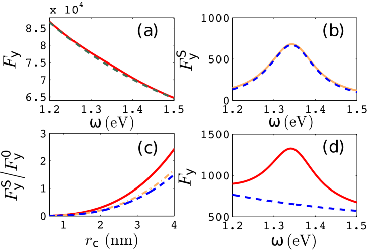
In Fig. 1(b/c) we show the spatial profile of the dipole mode of the LSP for the MNR with resonance around 1.34 eV [17], and we are interested in the frequency regime around the LSP. The FDTD [26] calculation of the homogeneous contribution is described in Ref. [11], and it can also be calculated analytically for a spherical RC [27, 28]. In Fig. 2(a), the homogeneous contribution to the enhanced SE rate (i.e., ) is shown by the green dashed line for a cavity with radius nm and refractive index (we use this value for the rest of our paper, but it can easily be changed). The FDTD calculation of the total enhancement (red solid) for the same cavity located 0.5 nm away from the center of the nanorod along the -axis (Fig. 1(b)) shows a bump around the LSP; it is found that the depolarization effect of the image dipole, , is negligible at this position. Due to the position of the resonance bump in , we expect it should be an indication of the LSP. An independent calculation of the scattering contribution via the QNM using Eq. (5) (blue dashed line in Fig. 2(b)) indeed shows excellent agreement with the difference between the total and homogeneous contribution of the enhancement, .
In Fig. 2(c) we show the ratio of to as a function of the radius of the RC. It can be seen as increases, the QNM contribution of the LSP begins to dominate over the homogeneous contribution. Figure 2(d) shows both and for a RC with radius nm; the contribution of the LSP is now larger than the homogeneous one, and it also shows a strong asymmetry around the LSP resonance.
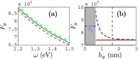
The above observation shows that our formulation, Eq. (8), works well for computing the LF effect, when the RC is at the center of the rod. But for a truly robust technique, it should also work near a surface. Thus in Fig. 3(a), we show the enhanced SE rate for a RC inside the nanorod but only 1.5 nm away from the top surface along the -axis (Fig. 1(c)): the green solid line is the FDTD result , and the magenta dashed is , which is seen to underestimate the total SE enhancement. Detailed calculation shows that the QNM contribution is now less than , and this can be explained by the mode profile of the QNM, for which the nodal lines lay around both ends of the nanorod. The orange dashed line in Fig. 3(a) is calculated with Eq. (8), and once again Eq. (8) agrees well with full FDTD calculation, where now it is important to include the scattering contribution from the image dipole. As shown in Fig. 3(b), the contribution of the image dipole begins to dominate over the homogeneous contribution when the separation between the cavity and the top surface comes into the sub-nm regime, although quantum tunneling effects near the surface may well also become important here.
Finally, since it is known that MNRs exhibit a large amount of quenching, we have also computed the output -factor, which is the probability that a single photon will be emitter into an output radiation mode, i.e., away from the MNR. For a 2 nm RC at the MNR center position, the -factor is around 9%, which is certainly large enough to get light in and out with reasonable efficiencies.
In summary, we have studied the LF problem for a finite-size lossy structure. Using a QNM technique, we have developed a semi-analytical formulation to compute the LF effect for a finite-size emitter inside a MNR. The accuracy of this approach is first confirmed by comparing with an established FDTD technique. The QNM LF approach enabled us to identify when one gets a significant contribution to the LF from the LSP resonance. We have also introduced an image dipole technique to obtain surface contributions for RCs that are near lossy surface. These LF models are of fundamental importance in quantum optics and could have applications for LSP lasing and spasing.
Funding Information
Natural Sciences and Engineering Research Council of Canada.
References
- [1] P. Lodahl, A. Floris van Driel, I. S. Nikolaev, A. Irman, K. Overgaag, D. Vanmaekelbergh, and W. L. Vos, Nature 430, 654 (2004).
- [2] L. Novotny and B. Hecht, Principles of Nano Optics, Cambridge University Press, (2006).
- [3] S. A. Maier, Plasmonics: Fundamentals and Appliations, (Springer, 2007).
- [4] J. Huh, C. Hermannstadter, K. Akahane, H. Sasakura, N. A. Jahan, M. Sasaki and I. Suemene, Jpn. J. Appl. Phys. 50 06GG02 (2011).
- [5] T. M.Babinec, Y. A. Kelaita, K. A. Fischer, K. G. Lagoudakis, T. Sarmiento, A. Rundquist, A. Majumdar, and J. Vuckovic, e-print: arXiv:1406.7050 (2014).
- [6] G. M. Kumar, D. N. Rao, and G. S. Agarwal, Opt. Lett. 30, 732 (2005).
- [7] S. Scheel, L. Knöll, and D.-G. Welsch, Phys. Rev. A 60, 4094 (1999).
- [8] S. Wheaton, R. M. Gelfand, R. Gordon, Nature Photonics 9, 68 (2015).
- [9] H. T. Dung, S. Y. Buhmann, and D.-G. Welsch, Phys. Rev. A 74, 023803 (2007).
- [10] T. M. Hien, H. T. Dung, and D.-G. Welsch, Phys. Rev. A 83, 043820 (2011).
- [11] C. Van Vlack, and S. Hughes, Opt. Lett. 37, 2880 (2012).
- [12] D. J. Bergman, and M. I. Stockman, Phys. Rev. Lett. 90, 027402 (2003).
- [13] M. A. Noginov, G. Zhu, A. M. Belgrave, R. Bakker, V. M. Shalaev, E. E. Narimanov, S. Stout, E. Herz, T. Suteewong, and U. Wiesner, Nature 460, 1110 (2009).
- [14] M. S. Tame, K. R. McEnery, S. K. Özdemir, J. Lee, S. A. Maier, and M. S. Kim, Nat. Phys. 9, 329 (2013)
- [15] P. T. Kristensen, and S. Hughes, ACS Photonics 1, 2 (2014).
- [16] R.-C. Ge, and S. Hughes, Opt. Lett. 39, 4235 (2014).
- [17] R.-C. Ge, P. T. Kristensen, Jeff. F. Young, S. Hughes, N. J. Phys 16, 113048 (2014).
- [18] C. Sauvan, J. P. Hugonin, I. S. Maksymov, and P. Lalanne, Phys. Rev. Lett. 110, 237401 (2013).
- [19] P. T. Leung, S. Y. Liu, and K. Young, Phys. Rev. A 49, 3982 (1994).
- [20] E. S. C. Ching, P. T. Leung, A. M. van den Brink, W. M. Suen, S. S. Tong, and K. Young, Rev. Mod. Phys. 70, 1545 (1998).
- [21] C. Belacel, B. Habert, F. Bigourdan, F. Marquier, J.-P. Hugonin, S. M. de Vasconcellos, X. Lafosse, L. Coolen, C. Schwob, C. Javaux, B. Dubertret, J.-J. Greffet, P. Senellart, and A. Maitre, Nano Lett. 13, 1516 (2013).
- [22] M. S. Toma, Phys. Rev. A 63, 053881 (2001).
- [23] K. M. Lee, P. T. Leung, and K. M. Pang, J. Opt. Soc. Am. B 16, 1409 (1999).
- [24] J. M. Gordon and Y. N. Gartstein, J. Opt. Soc. Am. B 31, 2029 (2014).
- [25] The electric field at the positioin of the dipole by the image dipole is with the dipole moment and the permittivity of free space.
- [26] We use FDTD Solutions: www.lumerical.com.
- [27] C. Van Vlack, P. T. Kristensen, and S. Hughes, Phys. Rev. B 85, 0765303 (2012).
- [28] L.-W. Li, P.-S. Kooi, M.-S. Leong, and T.-S. Yeo, IEEE Trans. Microwave Theor. Tech. 42, 2302 (1994).