Qubit-assisted transduction for a detection of surface acoustic waves near the quantum limit
Abstract
We demonstrate ultra-sensitive measurement of fluctuations in a surface-acoustic-wave (SAW) resonator using a hybrid quantum system consisting of the SAW resonator, a microwave (MW) resonator and a superconducting qubit. The nonlinearity of the driven qubit induces parametric coupling, which up-converts the excitation in the SAW resonator to that in the MW resonator. Thermal fluctuations of the SAW resonator near the quantum limit are observed in the noise spectroscopy in the MW domain.
Hybrid quantum systems have been widely studied in quantum information science Kurizkia2015 . Coherent control and quantum measurement across heterogeneous subsystems extend the applicability of quantum technologies towards quantum computers nakamura2010 , networks kimble2008 , repeaters briegel1998 and sensors degen2017 .
In solid-state systems, superconducting qubits nakamura1999 have been hybridized with a variety of other quantum degrees of freedom. The qubits provide strong nonlinearity originating in the Josephson effect as an important ingredient in the hybrid systems. For example, strong coupling with the systems such as microwave resonators walraff2004nat ; paik2011 , nanomechanical resonators OConnel2010 ; teufel2015 , bulk acoustic modes yale2017 , and paramagnetic Zhu2011 ; kubo2011 and ferromagnetic nakamura2015 spin ensembles have been demonstrated.
Recently, surface acoustic waves (SAW) have attracted much interest as an alternative quantum mode localized on a surface of a material delsing2012 ; leek2016 . In piezoelectric materials, SAW can be strongly coupled to electric fields between surface electrodes and are widely applied in compact microwave components because of their small wavelengths and losses datta1986 . Interaction of a SAW waveguide delsing2014 and a SAW resonator leek2017 with a superconducting qubit were recently demonstrated. SAW can also couple to other physical systems lukin2015 such as quantum dots santos2009 and NV centers wang2016 ; wang20162 through various form of elastic effects. Opto-elastic interaction of SAW opens the possibility to achieve a quantum transducer from microwave photons to optical photons in the telecommunication band shumeiko2016 ; Srinivasan2016 ; Okada .
In this Letter, we report experiments on a hybrid quantum system consisting of a SAW resonator, a superconducting qubit, and a MW resonator. We demonstrate microwave-driven parametric couplings induced by the nonlinearity of the qubit, which serves as a transducer or an interface between the phonons in the SAW resonator and the photons in the MW resonator. The thermal phonons in the sub-GHz SAW resonator are up-converted to the MW frequency range where near-quantum-limited measurement of photons is available. We observe thermal fluctuations in the SAW resonator below the mean phonon number of unity with an unprecedented sensitivity.
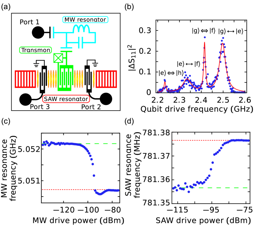
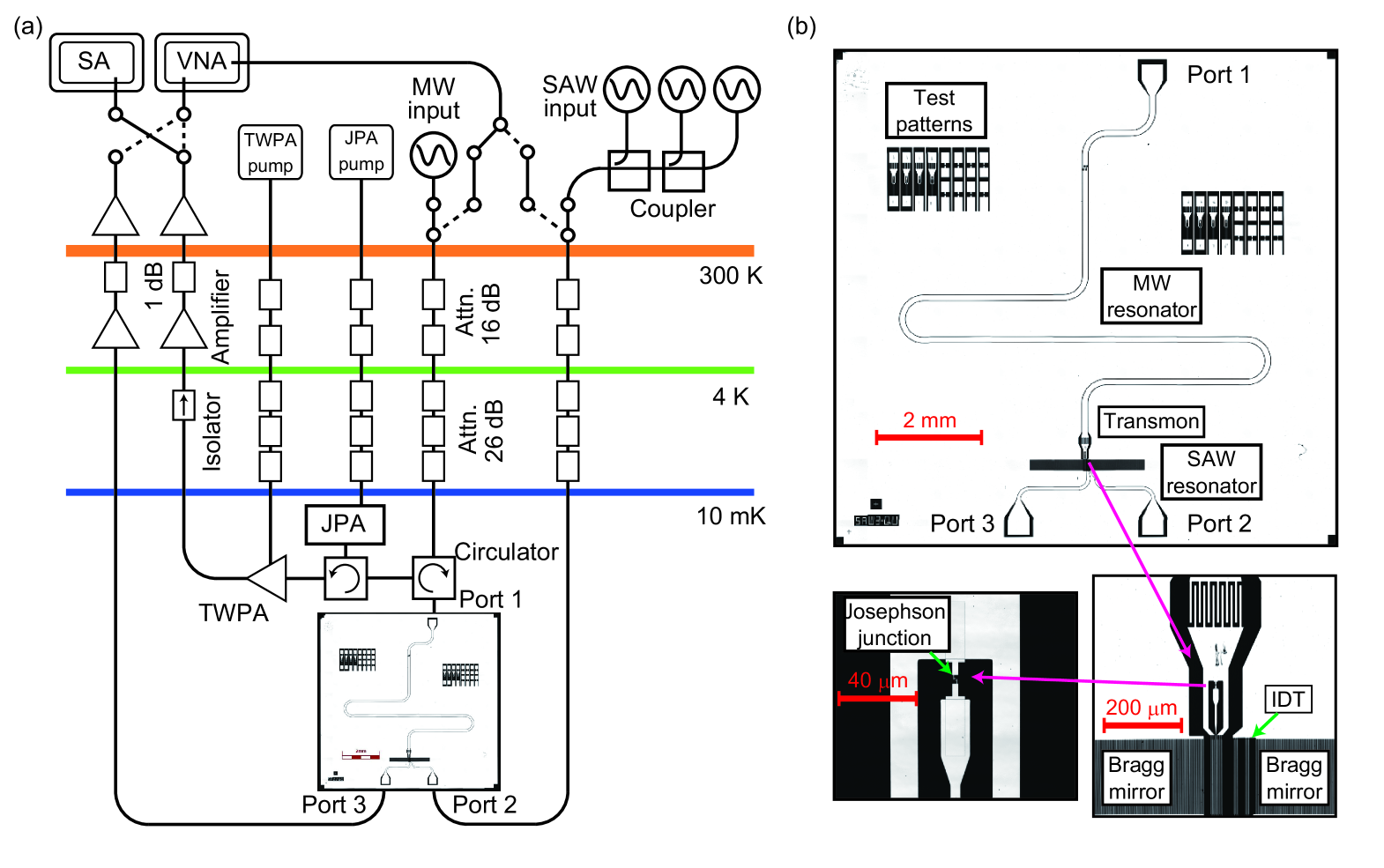
The hybrid device schematically illustrated in Fig. 1(a) is fabricated on a quartz substrate and cooled down to 10 mK in a dilution refrigerator (See the details in the Supplementary Information supple )). The Fabry-Pérot-type SAW resonator, defined by a pair of Bragg mirrors, couples piezoelectrically to a superconducting transmon qubit Koch2007 via an interdigitated capacitor. The qubit also couples capacitively to a half-wavelength coplanar-waveguide MW resonator. The MW resonator has a capacitively-coupled port on the other end (port 1). The SAW resonator has two interdigitated transducer ports (ports 2 and 3) for external coupling.
The hybrid system is modeled with a Hamiltonian under rotating-wave approximation
where is the Planck constant, () is the coupling strength between the MW (SAW) resonator, and and are the eigenfrequencies of the first excited state and the second excited state of the qubit. Here, () is the annihilation operator of the MW (SAW) resonator, and () are the operators in the energy eigenbasis of the transmon qubit.
We first characterize the system with spectroscopic measurements supple . Direct S-parameter spectroscopy is performed on the MW and SAW resonators. The MW resonator has the resonance frequency of GHz. The total linewidth is kHz, and the external coupling rate to port 1 is kHz. Similarly, the frequency and the linewidth of the SAW resonator are found to be MHz and kHz, respectively. The external coupling through the IDTs connected to ports 2 and 3 are Hz each. Thus, the SAW resonator is largely undercoupled.
Qubit parametrization can be achieved via the spectroscopy of the MW resonator to which the qubit is dispersively coupled. Figure 1(b) shows a qubit spectrum obtained by the two-tone spectroscopy via the MW resonator Schuster2005 . The eigenfrequencies are GHz and GHz, respectively. Thus, the qubit anharmonicity is evaluated to be MHz. Note that the lines corresponding to the parity-allowed two-photon transitions, and , are also observed, where is the third excited state of the qubit.
Some of the system characterization becomes much easier with the presence of the qubit inside the system. Coupling between the MW/SAW resonator to the qubit is measured quite conveniently using a simple decoupling technique with a strong drive Reed . Figures 1(c) and (d) show the drive power dependence of the MW and SAW resonance frequencies, respectively. A large frequency shift between the low- and high-power limits is observed. This frequency shift corresponds to (), which allows us to evaluate the coupling strength between the MW/SAW resonator and the qubit Suri . From Figs. 1(c) and (d) the coupling strengths and are evaluated to be MHz and MHz, respectively.
The coupling strength between the SAW resonator and the qubit can also be written as
| (2) |
where is the charge of the electron, is the capacitance of the IDT coupled to the qubit, is the total capacitance of the qubit, and is the zero point fluctuation of the surface potential of the SAW resonator. The capacitances are calculated from the geometrical design of the IDTs lukin2015 and are consistent with the single-electron charging energy of the qubit. From this equation we obtain the zero point fluctuation of the SAW resonator as . The zero point fluctuation of a SAW resonator is expected to be
| (3) |
where is the mode area of the SAW resonator (40,000 ). This leads to the surface piezoelectric potential of , which agrees well with the theoretical estimate for quartz lukin2015 . From these relations, the coupling strength is written as
| (4) |
Using the mode area of the SAW resonator, the zero point fluctuation in the unit of displacement is estimated as lukin2015 .
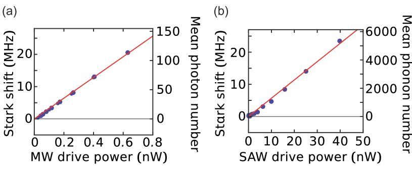
Dispersive interactions with the MW/SAW resonator makes the qubit subject to the AC Stark shifts proportional to the number of photons and phonons in each resonator. We use the effect as a calibration tool for the photon/phonon numbers in the resonators. Using the values of , we estimate the single photon/phonon Stark shifts of the qubit as () Suri and obtain kHz and kHz. Figure 2 shows the linear dependences of the AC Stark shifts on the MW and SAW drive powers. On the right axes, the corresponding intra-resonator photon/phonon numbers are indicated. The values of the Stark shifts per photon/phonon are smaller than the decay rates of the resonators and the qubit. Thus, the hybrid system is in the weak dispersive coupling regime.
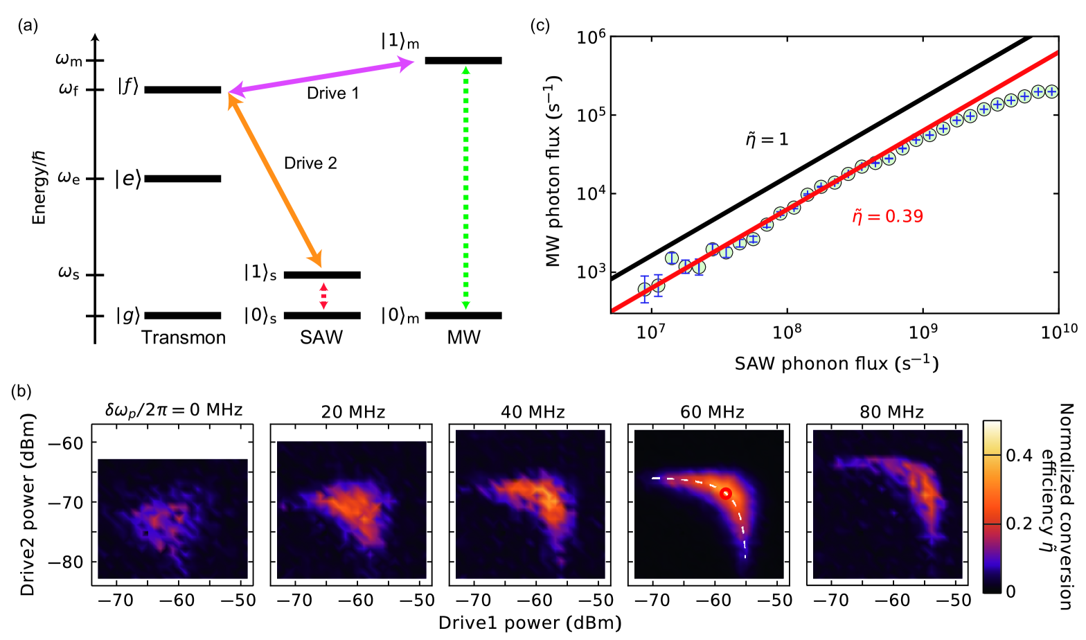
The MW resonator and the SAW resonator are not directly coupled to each other. Nevertheless, we can parametrically induce the coupling by driving the qubit, i.e., the nonlinear element in the system. The lowest-order parametric coupling is achieved by using the second excited state of the qubit. We strongly drive the qubit at the frequency as illustrated in Fig. 3(a). This drive (drive 1) induces the parametric coupling between the MW resonator and the second excited state of the qubit,
| (5) |
where is the coupling strength. Similarly, we also drive the qubit at . This tone (drive 2) induces the parametric coupling between the SAW resonator and the qubit
| (6) |
where is the coupling strength. Each coupling strength is written as Wallraff2014
| (7) |
where and () is the amplitude of drive 1 (drive 2). Note that this perturbative treatment is valid for the weak drive strength, where is smaller than and .
With the simultaneous drives of the two parametric processes, conversion between the MW photons and the SAW phonons is realized. Figure 3(b) shows the conversion efficiency from the SAW phonons to the MW photons as a function of the powers of drives 1 and 2. The color in the 2D plot indicates the normalized conversion efficiency, , where and are the external coupling factors of the MW and SAW resonators, respectively. In the series of measurements shown in the panels of Fig. 3(b), we optimize the conversion efficiency by varying the frequencies of the two drive tones, while keeping their sum fixed. Naively speaking, one would expect a better conversion efficiency with a higher driving power. However, the AC Stark effects induced by the drives shift the energy level of the second excited state of the qubit, and thus the detunings of the parametric drives depend on the power of the drives themselves. In the second panel from the right, we obtain the highest efficiency at the drive condition marked by the red circle. The white-dashed line delineates the condition where the sum of the Stark shifts is constant. The observed ‘arc’ is well fitted by the line, indicating that the large conversion efficiency is obtained when each parametric drive is in resonance with the relevant transition.
The conversion efficiency in the SAW-qubit-MW hybrid system reads Painter2012
| (8) |
where and are the cooperativities of the MW-qubit and the SAW-qubit coupled systems, respectively. Here MHz is the decay rate of the second excited state of the qubit. In Fig. 3(c), we plot the output MW photon flux from the MW resonator vs. the input SAW phonon flux . The data is taken under the optimized drive power condition indicated by the red circle in Fig. 3(b). The photon/phonon fluxes are calibrated based on the Stark shift measurements in the resonators. The black line depicts the relation , which indicates the upper limit of the conversion efficiency with the given external couplings. The red line is the linear fit to the data, showing the maximum conversion efficiency of . From the symmetry between drives 1 and 2 in the power dependence of the conversion efficiency observed in Fig. 2(b), as well as from the functional form of Eq. (8), we assume that the two cooperativities are equal at the optimal point. Then, the cooperativities are evaluated to be , which correspond to the parametrically induced coupling strengths of and for the MW and SAW resonators, respectively. The corresponding amplitudes of the drives are and , which satisfy the perturbative condition. The conversion efficiency is currently limited by the smallness of the external coupling of the SAW resonator . It can be overcome by using a high-Q SAW resonator or making the IDT electrodes large to enhance the external coupling of the SAW resonator.
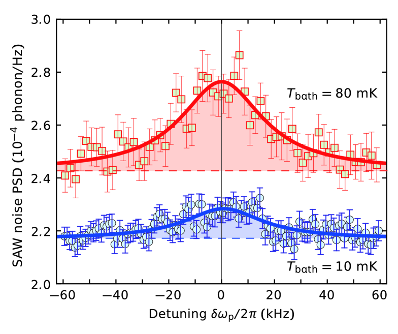
Finally we use the parametric conversion to analyze the thermal noise in the SAW resonator near the quantum ground state. Without any drive on the SAW resonator, the mean phonon number of the thermal excitation of the SAW resonator at the dilution fridge temperature of 10 mK is expected to be . We up-convert the SAW thermal fluctuation to that in the MW resonator through the parametric drives and measure the noise spectrum of the microwave output field using a cascade of a Josephson parametric amplifier Yamamoto_JPA and a traveling wave parametric amplifier TWPA (See supple for the details). Figure 4 shows the noise spectral density of the microwave resonator. The thermal noise in the SAW resonator manifests as an additional noise peak on top of the background. The linewidth of the peak agrees with . From the peak area, the mean phonon number in the SAW resonator is evaluated to be , corresponding to the effective temperature of mK, that is significantly higher than the bath temperature of 10 mK, presumably due to the bad thermalization. At a higher bath temperature of 80 mK, the mean phonon number increases to , corresponding to the effective temperature of mK. The displacement sensitivity of the measurement is evaluated as 0.2, two orders of magnitude improvement from the previous report delsing2012 .
In summary, we constructed a hybrid quantum system consisting of a SAW resonator, a transmon qubit, and a MW resonator. The interaction between the SAW and MW resonators were mediated by the parametrically driven qubit. We up-converted the SAW phonons to the MW photons and detected the thermal fluctuations of the SAW resonator near the quantum limit. It demonstrated an application of the hybrid quantum system to the ultra-sensitive measurement of the low-frequency SAW signals.
The conversion efficiency may be significantly improved to an order of unity. The external couplings of the resonators can be readily increased, and the SAW resonator quality factor can be at least an order of magnitude better with an optimized design. Moreover, the limitation in the parametrically induced coupling strengths due to the saturation effect of the transmon qubit can be mitigated with other types of nonlinear superconducting circuits.
A hybrid system in the strong coupling regime may also be achieved. The resonance frequency of the SAW resonator can be increased closer to the qubit frequency with shorter-period Bragg grating mirrors and IDT electrodes or with other materials which have a higher sound-velocity. The coupling strength between the SAW resonator and the qubit can be kept larger than their decay rates.
The SAW resonator can also be coupled to an optical system via the opto-elastic interaction shumeiko2016 ; Srinivasan2016 ; cleland2016 ; Okada . The hybrid system of the SAW resonator and the superconducting qubit opens the possibility of an optical access of superconducting qubit.
The authors acknowledge K. Kusuyama for the help in sample fabrication and W. Oliver for providing the Josephson traveling-wave parametric amplifier. This work was partly supported by JSPS KAKENHI (Grant Number 26220601), JST PRESTO (Grant Number JPMJPR1429), and JST ERATO (Grant Number JPMJER1601).
References
- (1) G. Kurizki, P. Bertet, Y. Kubo, K. Molmer, D. Petrosyan, P. Rabl, and J. Schmiedmayer, Quantum technologies with hybrid systems, Proc. Natl. Acad. Sci. U.S.A. 112, 3866 (2015).
- (2) T. D. Ladd, F. Jelezko, R. Laflamme, Y. Nakamura, C. Monroe, and J. L. O fBrien, Quantum computers, Nature 464, 45 (2010).
- (3) H. J. Kimble, The quantum internet, Nature 453, 1023 (2008).
- (4) H.-J. Briegel, W. Dur, J. I. Cirac, and P. Zoller, Quantum repeaters: the role of imperfect local operations in quantum communication, Phys. Rev. Lett. 81, 5932 (1998).
- (5) C. L. Degen, F. Reinhard, and P. Cappellaro, Quantum sensing, Rev. Mod. Phys. 89, 035002 (2017).
- (6) Y. Nakamura, Yu. A. Pashkin, and J. S. Tsai, Coherent control of macroscopic quantum states in a single-Cooper-pair box, Nature 398, 786 (1999).
- (7) A. Wallraff, D. I. Schuster, A. Blais, L. Frunzio, R.- S. Huang, J. Majer, S. Kumar, S. M. Girvin, and R. J. Schoelkopf, Strong coupling of a single photon to a superconducting qubit using circuit quantum electrodynamics, Nature 431, 162 (2004).
- (8) H. Paik, D. I. Schuster, L. S. Bishop, G. Kirchmair, G. Catelani, A. P. Sears, B. R. Johnson, M. J. Reagor, L. Frunzio, L. I. Glazman, S. M. Girvin, M. H. Devoret, and R. J. Schoelkopf, Observation of High Coherence in Josephson Junction Qubits Measured in a Three-Dimensional Circuit QED Architecture, Phys. Rev. Lett. 107, 240501 (2011).
- (9) A. D. O’Connell, M. Hofheinz, M. Ansmann, R. C. Bialczak, M. Lenander, E. Lucero, M. Neeley, D. Sank, H. Wang, M. Weides, J. Wenner, J. M. Martinis, and A. N. Cleland, Quantum ground state and single-phonon control of a mechanical resonator, Nature 464, 697 (2010).
- (10) F. Lecocq, J. D. Teufel, J. Aumentado, and R. W. Simmonds, Resolving the vacuum fluctuations of an optomechanical system using an artificial atom, Nat. Phys. 11, 365 (2015).
- (11) Y. Chu, P. Kharel, W. H. Renninger, L. D. Burkhart, L. Frunzio, P. T. Rakich, R. J. Schoelkopf, Quantum acoustics with superconducting qubits, arXiv:1703.00342 (2017).
- (12) X. Zhu, S. Saito, A. Kemp, K. Kakuyanagi, S. Karimoto, H. Nakano, W. J. Munro, Y. Tokura, M. S. Everitt, K. Nemoto, M. Kasu, N. Mizuochi, and K. Semba, Coherent coupling of a superconducting flux qubit to an electron spin ensemble in diamond, Nature 478, 221 (2011).
- (13) Y. Kubo, C. Grezes, A. Dewes, T. Umeda, J. Isoya, H. Sumiya, N. Morishita, H. Abe, S. Onoda, T. Ohshima, V. Jacques, A. Dreau, J. F. Roch, I. Diniz, A. Auffeves, D. Vion, D. Esteve, and P. Bertet, Hybrid Quantum Circuit with a Superconducting Qubit Coupled to a Spin Ensemble, Phys. Rev. Lett. 107 220501 (2011).
- (14) Y. Tabuchi, S. Ishino, A. Noguchi, T. Ishikawa, R. Yamazaki, K. Usami, and Y. Nakamura, Coherent coupling between a ferromagnetic magnon and a superconducting qubit, Science 349, 405 (2015).
- (15) M. V. Gustafsson, P. V. Santos, G. Johansson, and P. Delsing, Local probing of propagating acoustic waves in a gigahertz echo chamber, Nat. Phys. 8, 338 (2012).
- (16) R. Manenti, M. J. Peterer, A. Nersisyan, E. B. Magnusson, A. Patterson, and P. J. Leek, Surface acoustic wave resonators in the quantum regime, Phys. Rev. B 93, 041411 (2016).
- (17) S. Datta, Surface Acoustic Wave Devices (Prentice-Hall, Upper Saddle River, NJ, 1986).
- (18) M. V. Gustafsson, Th. Aref, A. F. Kockum, M. K. Ekstrom, G. Johansson, and P. Delsing, Propagating phonons coupled to an artificial atom, Science 346, 207 (2014).
- (19) R. Manenti, A. F. Kockum, A. Patterson, T. Behrle, J. Rahamim, G. Tancredi, F. Nori, and P. J. Leek, Circuit quantum acoustodynamics with surface acoustic waves, arXiv:1703.04495 (2017).
- (20) M. J. A. Schuetz, E. M. Kessler, G. Giedke, L. M. K. Vandersypen, M. D. Lukin, and J. I. Cirac, Universal quantum transducers based on surface acoustic waves, Phys. Rev. X 5, 031031 (2015).
- (21) O. D. D. Couto, Jr , S. Lazic, F. Iikawa, J. A. H. Stotz, U. Jahn, R. Hey, and P. V. Santos, Photon anti-bunching in acoustically pumped quantum dots, Nat. Photo. 3, 645 (2009).
- (22) D. A. Golter, Th. Oo, M. Amezcua, I. Lekavicius, K. A. Stewart, and H. Wang, Coupling a Surface Acoustic Wave to an Electron Spin in Diamond via a Dark State, Phys. Rev. X 6, 041060 (2016).
- (23) D. A. Golter, Th. Oo, M. Amezcua, K. A. Stewart, and H. Wang, Optomechanical Quantum Control of a Nitrogen-Vacancy Center in Diamond, Phys. Rev. Lett. 116, 143602 (2016).
- (24) V. S. Shumeiko, Quantum acousto-optic transducer for superconducting qubits, Phys. Rev. A 93, 023838 (2016).
- (25) K. C. Balram, M. I. Davanco, J. D. Song, and K. Srinivasan, Coherent coupling between radiofrequency, optical and acoustic waves in piezo-optomechanical circuits, Nat. Photo. 10, 346 (2016).
- (26) A. Okada, F. Oguro, A. Noguchi, Y. Tabuchi, R. Yamazaki, K. Usami, and Y. Nakamura, Cavity optomechanics with surface acoustic waves, arXiv:1705.04593 (2017).
- (27) Supplementary Information
- (28) J. Koch, T. M. Yu, J. Gambetta, A. A. Houck, D. I. Schuster, J. Majer, A. Blais, M. H. Devoret, S. M. Girvin, and R. J. Schoelkopf, Charge-insensitive qubit design derived from the Cooper pair box, Phys. Rev. A 76, 042319 (2007).
- (29) D. I. Schuster, A. Wallraff, A. Blais, L. Frunzio, R.-S. Huang, J. Majer, S. M. Girvin, and R. J. Schoelkopf, ac Stark shift and dephasing of a superconducting qubit strongly coupled to a cavity field, Phys. Rev. Lett. 94, 123602 (2005).
- (30) M. D. Reed, L. DiCarlo, B. R. Johnson, L. Sun, D. I. Schuster, L. Frunzio, and R. J. Schoelkopf, High-Fidelity Readout in Circuit Quantum Electrodynamics Using the Jaynes-Cummings Nonlinearity, Phys. Rev. Lett. 105, 173601 (2010).
- (31) B. Suri, Z. K. Keane, L. S. Bishop, S. Novikov, F. C. Wellstood, and B. S. Palmer, Nonlinear microwave photon occupancy of a driven resonator strongly coupled to a transmon qubit, Phys. Rev. A 92, 063801 (2015).
- (32) M. Pechal, L., Huthmacher, C. Eichler, S. Zeytinoglu, A. A. Abdumalikov, Jr., S. Berger, A. Wallraff, and S. Filipp, Microwave-Controlled Generation of Shaped Single Photons in Circuit Quantum Electrodynamics, Phys. Rev. X 4, 041010 (2014).
- (33) J. Hill, A. H. Safavi-Naeini, J. Chan, and O. Painter, Coherent optical wave-length conversion via cavity optomechanics. Nat. Commun. 3, 1196 (2012).
- (34) T. Yamamoto, K. Inomata, M. Watanabe, K. Matsuba, T. Miyazaki, W. D. Oliver, Y. Nakamura, and J. S. Tsai, Flux-driven Josephson parametric amplifier, Appl. Phys. Lett. 93, 042510 (2008).
- (35) C. Macklin, K. O’Brien, D. Hover, M. E. Schwartz, V. Bolkhovsky, X. Zhang, W. D. Oliver, I. Siddiqi, A near-quantum-limited Josephson traveling-wave parametric amplifier, Science 350, 307 (2015).
- (36) A. Vainsencher, K. J. Satzinger, G. A. Peairs, and A. N. Cleland, Bi-directional conversion between microwave and optical frequencies in a piezoelectric optpmechanical device, Appl. Phys. Lett. 109, 033107 (2016).
Supplementary Information for
Qubit-assisted transduction for a detection of surface acoustic waves
near the quantum limit
Measurement setup
Figure S1 illustrates the microwave measurement setup for the SAW-MW parametric conversion and the thermal noise detection. The sample is cooled down to 10 mK in a dilution refrigerator. Attenuators are mounted on the input coaxial cables at each plate of the fridge to prevent the thermal noise from entering the resonators. The qubit drive and the SAW drive are combined in a series of directional couplers and applied via the SAW input line (port 2). A probe field for the MW resonator is supplied through the MW input line (port 1). The reflection signal from the MW resonator is observed with a spectrum analyzer (SA) or a vector network analyzer (VNA) through a cascade of a flux-driven Josephson parametric amplifier (JPA) Yamamoto_JPA , a traveling wave parametric amplifier (TWPA) TWPA at base temperature and low-noise HEMT amplifiers at 4 K and room temperature. Port 3 is for the transmission measurement of the SAW resonator.
Sample
The circuit is fabricated on a 300-m-thick ST-X cut quartz substrate. The Bragg mirrors and the interdigitated transducers (IDTs) for the SAW resonator, the coplanar waveguide for the MW resonator, and the capacitance of the qubit are made from a 300-nm-thick evaporated aluminum film. They are simultaneously patterned in a wet-etching process. The Bragg mirrors have 500 fingers each. The IDTs for the external coupling have a pair of three fingers each, and the IDT connected to the qubit has a pair of eight fingers. All those fingers have the line width and the spacing of 1 m. The length of the SAW resonator (the inner distance between the Bragg mirrors) is 140 . The widths of the Bragg mirrors and the IDTs are 200 m.
The Josephson junction of the qubit is made from an Al/AlOx/Al junction, which is fabricated by the shadow evaporation technique. The size of the junction is , and the resistance of the junction at the room temperature is 30 k. The single-electron charging energy and the Josephson energy of the transmon qubit are estimated to be and , respectively.
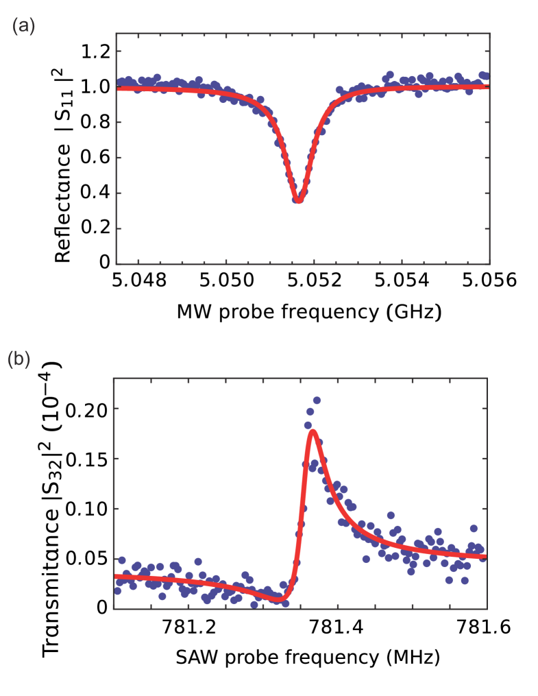
Characterization of resonators
Figure S2 shows the reflection and transmission spectra of the MW and SAW resonators, respectively. From the results we deduce the frequencies and the linewidths of the resonators presented in the main text.
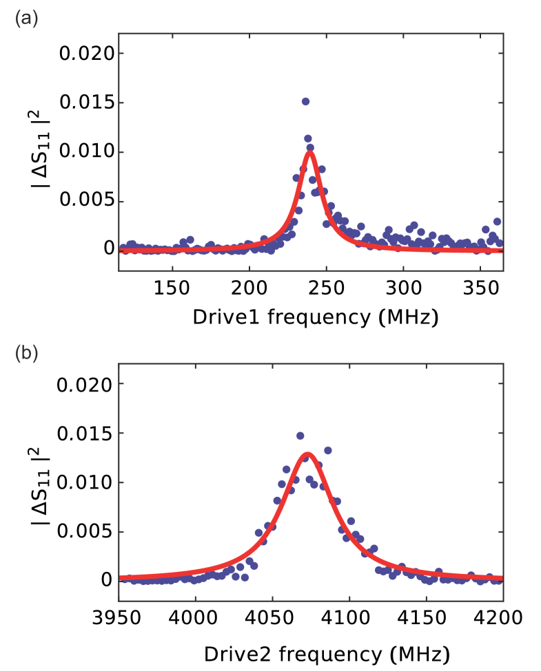
Parametric transition spectroscopy
When we apply a drive field at a frequency close to , the parametric coupling occurs between , where is the eigenfrequency of the second excited state of the qubit and ( is the resonator frequency. With the parametric drive at resonance, the resonator is dressed by the second excited state of the qubit, and the reflection coefficient of the resonator changes. The results in Fig. S3 determine the drive frequencies for the parametric couplings of the qubit with the SAW/MW resonators.
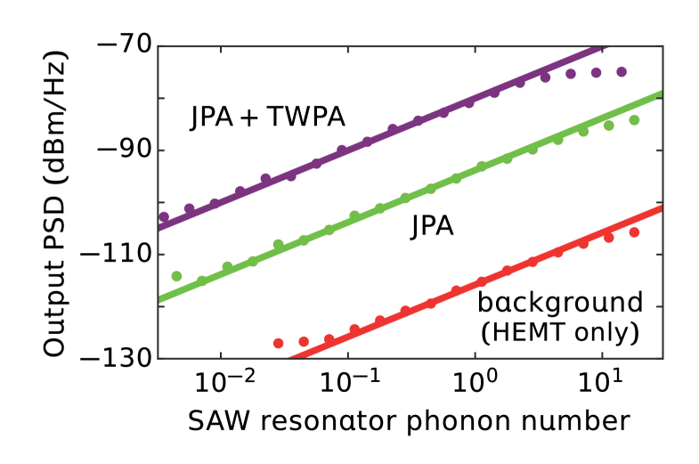
Amplifiers
Figure S4 shows the gain calibration of the amplifiers. The horizontal axis is the intra-resonator mean phonon number of the SAW resonator, which is calibrated by the Stark-shift measurement in Fig. 2 of the main text. The vertical axis represents the power spectral density (PSD) of the output microwave field at the spectrum analyzer (Fig. S1). The purple, green and red dots show the results with JPA+TWPA, JPA, and without them, respectively. From the data, the gains of the JPA and the TWPA are determined to be 22 dB and 14 dB, respectively. The measurement in Fig. 3 is conducted with JPA+TWPA in the linear region below the saturation point around three intra-resonator SAW phonons.
References
- (1) T. Yamamoto, K. Inomata, M. Watanabe, K. Matsuba, T. Miyazaki, W. D. Oliver, Y. Nakamura, and J. S. Tsai, Flux-driven Josephson parametric amplifier, Appl. Phys. Lett. 93, 042510 (2008).
- (2) C. Macklin, K. O’Brien, D. Hover, M. E. Schwartz, V. Bolkhovsky, X. Zhang, W. D. Oliver, I. Siddiqi, A near-quantum-limited Josephson traveling-wave parametric amplifier, Science 350, 307 (2015).