Recent Developments in DEMIRCI, the RFQ Design Software
Abstract
The RFQ design tool DEMIRCI aims to provide fast and accurate simulation of a light ion accelerating cavity and of the ion beam in it. It is a modern tool with a graphical user interface leading to a "point and click" method to help the designer. This article summarizes the recent developments of DEMIRCI software such as the addition of beam dynamics and 8-term potential coefficient calculations. Its results are compared to other software available on the market, to show the attained compatibility level. Finally the future prospects are discussed.
1 Introduction
Since their proposal by Kapchinsky and Tepilyakov (K-T) [1], the radio frequency quadrupoles (RFQ) are being used to bunch, focus and accelerate ion-beams to energy levels high enough to be used at the drift tube linacs (DTL) with various degrees of success. The successful operation of an RFQ, requires a rapid and realistic design and simulation of the cavity and the ion beam within. An accurate and easy design process has proven to be a challenge since the specifications dictated by research community and industry become ever more demanding. The complexities in low energies makes it harder to design and to make simple predictions based on that design. Using multiple computer intensive simulations at each iteration and manually keeping track of the various design tools used together, is error prone and time consuming. There is a limited number of such computer programs, PARMTEQ and LIDOS being the leading examples [3, 2]. DEMIRCI was born out of the need for a simple-to-use, yet a tool with multiple capabilities. Its first version [4, 5], allowed a very basic design using only two term potential but provided the graphical means for helping the inexperienced user. Since than the variable set that can be plotted has been enlarged, it was made multi-lingual and available in windows operating system. The details of these enhancements are discussed elsewhere [6]. This note will focus on much more recent developments such as eight term potential multipole coefficients calculation, beam dynamics simulations with eight or two terms and RFQ acceptance calculations and plots.
2 Recent Developments
The recent work has been focusing on the calculation of the eight term (8T) potential multipole coefficients in a fast and accurate way, on using these coefficients to track the macro-particles in the RFQ, and finally on using this mechanism to both visualize the beam behavior and to calculate the RFQ acceptance and mismatch factor for a given low energy beam.
2.1 Eight Term Potential
Designing an RFQ, consisting of about hundred cells, necessitates correct determination of the time independent part of the electrical K-T potential for each cell given [1]by:
where and are spherical coordinates for which represents the beam direction, is the inter-vane voltage, is the wave parameter given by , with being the RF wavelength and being the speed of the ion relative to the speed of light. Also, is the mean aperture of the vanes, is the modified Bessel function of order and the are the multipole coefficients whose values, depending on the vane geometry, should be obtained. The heritage from the very first RFQ studies in LANL can still be found in the industry standard software PARMTEQ’s [3] method to determine the multipole coefficients of the first 8 terms. It is based on data from pre-prepared tables containing image charge calculations using the integral method. Another approach reported in the literature uses a 3 dimensional differential finite element method to obtain the potential distribution across the RFQ length and then does a least squares fit to obtain the multipole coefficients [7]. Since this method is reported to be as accurate as the image charge method and much faster from computation point of view, an independent implementation of this approach is realized in DEMIRCI.
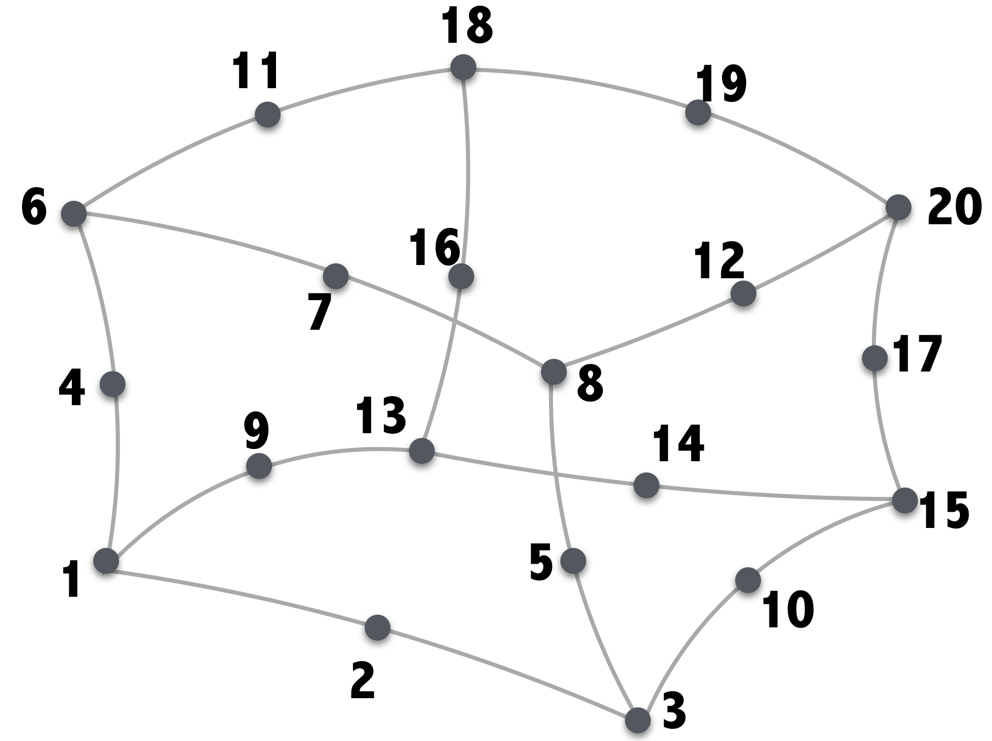
The procedure for finding the 8T coefficients starts with the division of the RFQ to be simulated into a number 20 node bricks as shown in Figure 1. Although the number of segmentations in 3D is user selectable, a good compromise between speed and accuracy is encoded as the default value set: 5x5x6 in , and coordinates. Once the meshing is complete, the general stiffness matrix is prepared from individual segments. Finite element method (FEM) is used to formulate the Poisson equation to find the electrostatic potential for each cell. This equation is solved numerically using the conjugate gradient technique for each node and for each cell. The solutions for the nodes within the minimum bore radius are then fitted to the 8T potential function with the least squares method to find the first eight KT potential coefficients at each cell.
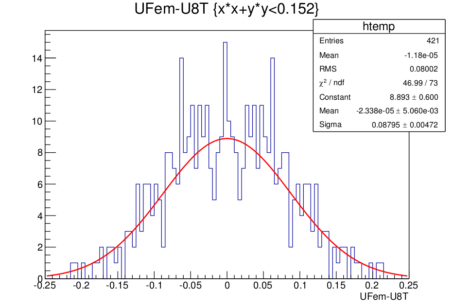
The validity of the method and of the results are checked using two different approaches. Firstly, a similar RFQ 8T coefficient calculation report has been found and the same calculations are repeated in DEMIRCI. The encouraging results of that study are reported elsewhere [8]. As an additional check, FEM solutions on all nodes are compared to fit results for a random cell. The histogram of the difference between the two are shown in Figure 2 together with a gaussian fit. The distribution shows that the error originating from the fitting procedure is about 1/1000. Even if in some long cells, the 8T potential is not adequate for defining the equipotential surface, the error is smoothed out by the fitting procedure and it’s order of magnitude is expected to remain at this level.
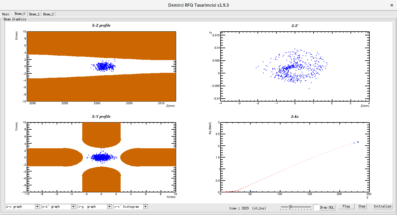
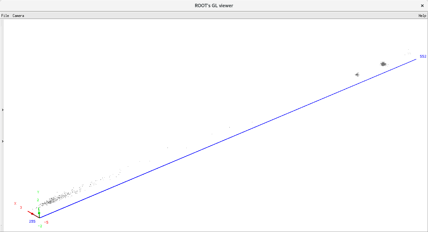
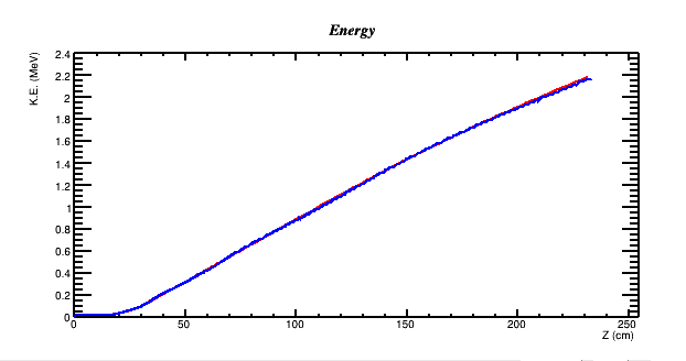
Once all the 8T potential coefficients are calculated, the Beam Dynamics tabs of the DEMIRCI graphical user interface, shown in Figure3, become available to the designer. The designer has three such tabs with four user selectable beam dynamics related plots are available. For the beam dynamics calculations a constant time step (set as 0.1ns, not adjustable by the user) based approach is used for finding all relevant EM fields, particle positions and velocities during the simulation. Synchronous particle energy calculated with these fields closely follows the predicted kinetic energy for our test design as shown in the Figure 5. Another visualization facility available to the designer is the 3D beam view shown in Figure 4. In this particular example, where the synchronous particle is at 520mm from the origin, the bunched and accelerated particles are shown along the axis.
3 Comparisons with similar software
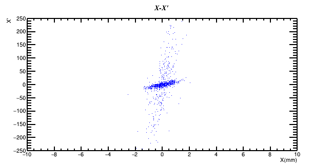
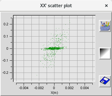
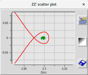
To ensure compatible results with already available software, the same RFQ design has been fed into both DEMIRCI and TOUTATIS[9]. Figure 6 shows the phase space at around =2300mm as obtained from both DEMIRCI and TOUTATIS. The is defined as[10]:
| (2) |
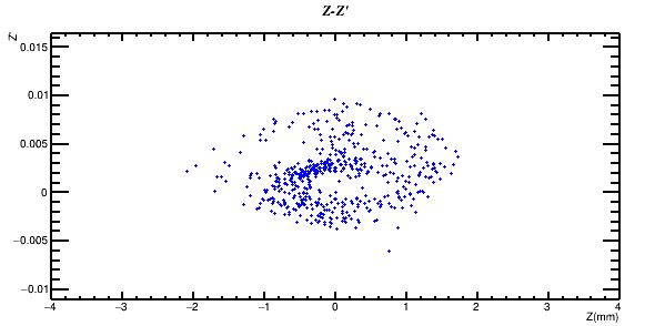
where the subscript () stands for the next (current) position of a particle. A similar plot set, shown in Figure7 is also made for the phase space where is defined using the velocity of the synchronious particle ( ) along the direction:
| (3) |
One can thus see the relation between the position of the particles and their velocities showing the details of the bunching process. Both plots have DEMIRCI results at the top and TOUTATIS results at the bottom. Although it is hard to read the values from the TOUTATIS plots, the order of magnitude of the phase spaces coincide and both programs show similar bunching structures.
4 Outlook
DEMIRCI is being developed continuously to match the requirements of both national and international RFQ designer communities. Its graphically oriented easy to use user interface together with its fast and accurate calculations could make it the tool of choice for designers. To improve its simulation capabilities at high current values, both image and space charge simulations will be added in the next versions. Additionally a new project for producing a short RFQ to compare its EM fields to DEMIRCI predictions is submitted for funding.
5 Acknowledgment
This project has been supported by TUBITAK with project number 114F106.
References
- [1] I.M. Kapchinsky an V. A. Teplyakov, "A Linear Ion Accelerator with Spatially Uniform Hard Focusing", ITEP-673, 1969.
- [2] LIDOS.RFQ.DESIGNER Version 1.3, http://www.ghga.com/accelsoft/
- [3] Kenneth R. Crandall, Thomas P. Wangler, Lloyd M. Young, James H. Billen, George H. Neuschaefer, and Dale L. Schrage, PARMTEQ-RFQ Design Codes.
- [4] A. Alacakir, B. Yasatekin, G. Turemen and G. Unel, "Design Studies with DEMIRCI for SPP RFQ", in Proc. of the Linear Accelerator Conference 2014 (LINAC’14), 31 Aug - 5 Sep 2014, paper TUPP139, p. 740.
- [5] B. Yasatekin, G. Turemen and G. Unel, A Graphical Approach to Radio Frequency Quadrupole Design, Computer Physics Communications, Volume 192, 108-113, 2015.
- [6] B. Yasatekin, G. Turemen, E. Celebi, G. Unel, O. Cakir, DEMIRCI, "An RFQ Design Software", in Proc. International Computational Accelerator Physics Conference (ICAP’15), 12-16 October 2015, paper WEP10.
- [7] N.J. Diserens, "RFQCOEF, A Package for Extracting the Harmonic Coefficients for the Potential Function in an RF Quadrupole Cell", in Proc. Linear Accelerator Conference (LINAC’84), Seeheim, Germany, 1984, paper THP0002.
- [8] B. Yasatekin, G. Turemen, E. Celebi, G. Unel, O. Cakir, “Demirci - V2 ”, in preparation.
- [9] R. Duperrier, “TOUTATIS: A Radio Frequency Quadrupole Code”, Phys. Rev. Vol.3, 124201, 2000.
- [10] T. Wangler, “Principles of RF Linear Accelerators”, Wiley and sons, ISBN 0-471-16814-9, 1998.