Relativistic Two-fluid Simulations of Guide Field Magnetic Reconnection
Abstract
The nonlinear evolution of relativistic magnetic reconnection in sheared magnetic configuration (with a guide field) is investigated by using two-dimensional relativistic two-fluid simulations. Relativistic guide field reconnection features the charge separation and the guide field compression in and around the outflow channel. As the guide field increases, the composition of the outgoing energy changes from enthalpy-dominated to Poynting-dominated. The inertial effects of the two-fluid model play an important role to sustain magnetic reconnection. Implications for the single-fluid magnetohydrodynamic approach and the physics models of relativistic reconnection are briefly addressed.
Subject headings:
magnetic fields — MHD — plasmas — relativity1. INTRODUCTION
The role of magnetic fields has been recognized in various contexts of relativistic astrophysics: pulsars, magnetars, gamma-ray bursts (GRBs), active galactic nuclei (AGNs), and black holes. Owning to its fundamental nature, relativistic magnetic reconnection in electron–positron pair plasmas (or in pairs and baryons) has drawn attentions in these sites as well; however, its mechanisms are poorly understood. Despite several theoretical attempts over decades (Blackman & Field, 1994; Lyutikov & Uzdensky, 2003; Lyubarsky, 2005), the most important properties of relativistic magnetic reconnection such as the energy conversion rate and the released energy composition are still under debate, especially in the magnetically dominated limit.
Relativistic magnetohydrodynamic (RMHD) codes are very desirable to study the theories of relativistic magnetic reconnection and to investigate astrophysical problems which involve magnetic reconnection. However, surprisingly, reconnection or non-ideal RMHD problems were left untouched until Watanabe & Yokoyama (2006) carried out resistive RMHD simulations. They exhibited a Petschek-like structure with an Alfvénic outflow and showed that relativistic reconnection is faster than the nonrelativistic counterpart. Several groups have developed resistive RMHD codes (Komissarov, 2007; Palenzuela et al., 2009; Dumbser & Zanotti, 2009), which can be applied to the reconnection problems as well. Recently, Zenitani et al. (2009) employed a relativistic two-fluid model to simulate magnetic reconnection. They obtained Petschek-type steady reconnection in a large system and found that the reconnection speed becomes faster and faster in magnetically dominated regimes.
In addition to the basic antiparallel configuration, reconnection with a current-aligned magnetic field (the “guide field”) is likely in magnetic shear and in celestial flare situations. It is well known that guide field reconnection behaves differently from its anti-parallel counterpart. In the relativistic regime, it is expected to change the energy composition in the outflow in RMHD scales (Lyubarsky, 2005). However, the RMHD/fluid-scale behavior of relativistic guide field reconnection has not yet been explored by simulations.
In kinetic scales, it has been found that reconnection is a powerful particle accelerator in both antiparallel and guide field configurations (Zenitani & Hoshino, 2001, 2007, 2008; Jaroschek et al., 2004). Since the plasma nonthernal energy is comparable with or exceeds the thermal part, we expect that kinetic physics significantly affects the global dynamics. Comparison with RMHD/fluid models is useful to understand the role of kinetic physics.
The purpose of this paper is to advance our two-fluid reconnection work (Zenitani et al., 2009) another step forward. In the earlier work, we assumed symmetric motions of the two species, which enforced the charge neutrality in the system. In this work, we solve two fluid motions independently. This allows us to explore broader ranges of physical targets, which involve charge separation. Using relativistic full two-fluid simulations, we will investigate a nonlinear development of a relativistic reconnection system with a guide field.
2. NUMERICAL SETUP
We use the following set of relativistic fluid equations and Maxwell equations. The subscript denotes species (‘’ for positrons and ‘’ for electrons). Similar equations for electrons are considered too:
| (1) |
| (2) |
| (3) |
| (4) | |||||
| (5) |
| (6) | |||||
| (7) |
In these equations, is the Lorentz factor, is the proper density, is the fluid 4-velocity, is the enthalpy with the specific heat ratio , is the Kronecker delta, is the proper pressure, is the positron/electron charge, is the electric current, and is the charge density. In the momentum and the energy equations, inter-species friction terms with the coefficient are added. They are revised from our previous work. The new form is similar to a covariant form in Gurovich & Solov’ev (1986). The variables and are virtual potentials for divergence cleaning (Munz et al., 2000; Dedner et al., 2002; Komissarov, 2007), whose propagation speed and the decay rate are and , respectively.
We study two-dimensional system evolutions in the – plane. We use the Harris-like model as an initial configuration: the magnetic field, the (proper) density, and the pressure are , , and , respectively. Here, is the current sheet thickness, is the guide field amplitude, and is the background proper density. The initial out-of-plane current is sustained by the fluid drift of . This restricts the electron inertial length () and the Larmor radius () to sufficiently small values. We set the reconnection point at the origin in the system domain of or . In order to reduce the computational cost, we assume that the system is point-symmetric around the reconnection point: or for all times. The boundary conditions at are set accordingly. At the other three boundaries, we basically consider the Neumann boundary conditions (), and the normal components of the fields ( and ) are adjusted to satisfy and . We employed the spatially localized resistivity, which is controlled by the coefficient . The effective Reynolds number of the frictional resistivity is near the reconnection point and in the background region. We normalize timescales by the light transit time . The decay time scale for divergence cleaning is set to .
We studied the guide field effect by changing as shown in Table 1. We consider the magnetization parameters , the ratio of the Poynting flux to the plasma energy flux. In the inflow region, , where and are contributions from and . The parameter is set to and the relevant Alfvén velocity is . The other parameter depends on .
The system evolution is solved by the modified Lax–Wendroff scheme with a small artificial viscosity, whose viscous coefficient depends on the local gradient of the fluid 4-velocity. We directly solve quartic equations to recover the primitive variables (Zenitani et al., 2009). The results are checked by changing the system size, the left boundary conditions (with or without the point symmetry), the time and spatial resolutions, and parameters for the numerical stability.
| Run | Domain Size | Grid Points | |||
|---|---|---|---|---|---|
| 1 | 120 120 | 2400 2400 | 0.0 | 0.0 | 0.142 |
| 2 | 120 120 | 2400 2400 | 0.25 | 0.25 | 0.126 |
| 3a | 120 120 | 2400 2400 | 0.5 | 1.0 | 0.102 |
| 3b | 240 120 | 4800 2400 | 0.5 | 1.0 | 0.102 |
| 4 | 120 120 | 2400 2400 | 1.0 | 4.0 | 0.074 |
| 5 | 120 120 | 2400 2400 | 1.5 | 9.0 | 0.055 |
Note. — The initial guide field , the ratio of the its Poynting flux to the plasma energy flux , and typical steady reconnection rates .
3. SIMULATION RESULTS
3.1. Overview
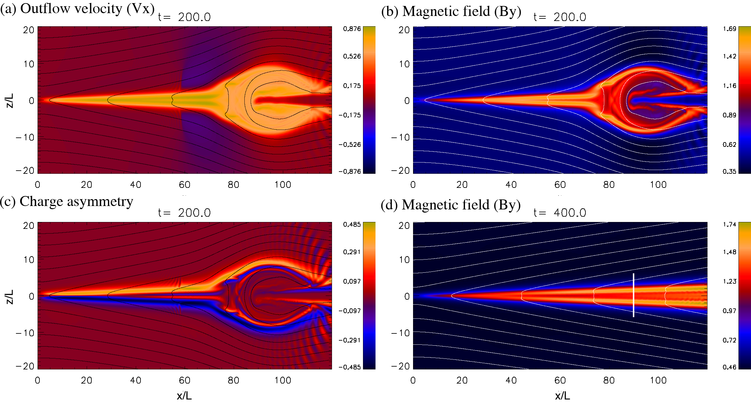
Snapshots of runs 3b with a guide field are presented in Figure 1. Shown in Figure 1a is an outflow structure of the plasma mean number flow,
| (8) |
We see that a fast outflow jet travels to the magnetic island (plasmoid) in the downstream region. Since there are ambient current sheet plasmas, the plasmoid exhibits a crab claw structure in the downstream, similar to large-scale MHD simulations of nonrelativistic magnetic reconnection (e.g., Abe & Hoshino (2001)). Inside the outflow channel, the flow speed is . The maximum 4-velocity of each species is . These speeds are slightly slower than the antiparallel counterpart. The backward flows around (blue regions; ) are reverse flow from the plasmoid. Since the downstream plasmoid expands, the surrounding magnetic fields are compressed and then its magnetic pressure expels the plasma along the field lines. Sharp boundaries at are the fronts of such backward flows.
Shown in Figure 1b is the out-of-plane magnetic field . We see that the guide field is compressed at the edge of the plasmoid and in the narrow reconnection outflow region, because the incoming reconnection flows transport and pile up the magnetic flux from the upstream region. Such -compression changes the composition of outgoing energy flux in relativistic magnetic reconnection.
Figure 1c shows the charge separation, . The charge density looks similar. We see that positrons dominate in the upper of the outflow region, and electrons in the lower. The charge separation generates the electric fields in the – plane: in the upper half of the inflow region, in the lower half of the inflow region, and in the rightward outflow region. The condition with the guide field is consistent with the reconnection flow pattern. It is impressive to see that the non-neutral layers extend over the large spatial domain and that the charge separation is strong 0.5. Such a non-neutral structure is qualitatively consistent with positron-rich or electron-rich regions around the reconnecting diffusion region in previous kinetic work (Zenitani & Hoshino, 2008).111Charge signs are opposite from Figure 2(c) in Zenitani & Hoshino (2008), because the guide field is set oppositely. Stripes around are transient oscillations invoked by the reverse flow. As the system evolves, the plasmoid and the reverse flows move further away. We also see strong perturbations around , where the plasmoid hits the ambient plasmas.
Later, the system approaches to a quasi-steady stage. Shown in Figure 1d is a late-time structure of at in run 3b. We see that the outflow structure in Figure 1b straightforwardly extends toward the direction. The backward flow fronts are outside the presented domain at this time. The in-plane magnetic fields show a narrow Petschek-type structure. Interestingly, the -structure is weakly bifurcated, and then the two peaks separate the outflow channel into three layers. We examine the outflow channel structure in Section 3.4. Around , the bifurcated peaks exhibit a very weak wave structure, probably due to a velocity–shear driven instability. This introduces a minor oscillation inside the central channel in the further downstream; however, it does not change the global outflow structure. We also confirmed that the global outflow structure does not depend on the domain size by comparing runs 3a and 3b. Therefore, the outflow boundary condition does not change the physics.
We believe that the large distance to the upstream boundary () is virtually eliminates boundary effects on the simulation. The plasmoid and reconnected field lines are well confined in – in panels in Figure 1. In the steady stage of , the slope angle of the field lines is only around the outflow region, and it becomes even smaller further upstream. For example, in the vicinity of the top boundary, the field line at is connected to .
3.2. Reconnection electric field
The reconnection electric field at the -point presents the transfer rate of the antiparallel magnetic fields from the upstream region. Since the surrounding conditions change in time, the normalized rate or “reconnection rate” gives a good measure of the system evolution. Here we define the rate as
| (9) |
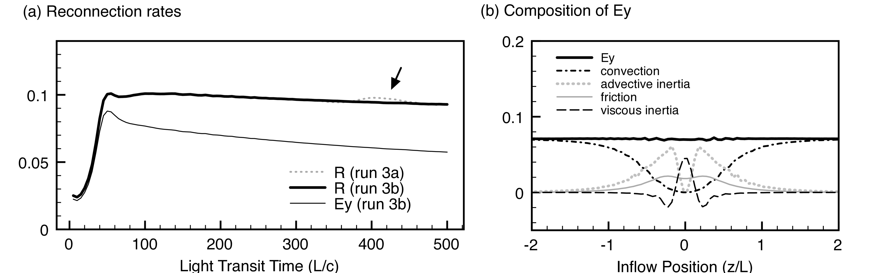
where the subscript denotes the upstream properties at . The time evolution of the rates is shown in Figure 2a, and we see that the (normalized) reconnection becomes constant after the initial ramp up for . For comparison, the rate for run 3a is presented, too. Runs 3a and 3b are in excellent agreement except for around (indicated by an arrow) when the boundary effect temporally comes back to the reconnection point in the smaller run 3a. In Table 1, we present the peak values of the quasi-steady reconnection rates for all other runs.
So, what sustains such quasi-steady evolution of magnetic reconnection? In other words, what is responsible for the reconnection electric field around the -point in our simulations? We study the composition of near the -point using the Ohm’s law. Combining the momentum equations (Equation 2) of the two species, we obtain the following relation:
| (10) | |||||
where is the specific enthalpy. Note that we drop the time derivatives considering the quasi-steady condition (). In addition, along the inflow line (), we find , , , , and , and so the equation can further be simplified. We can also approximate that the artificial viscosity works for in a form of with an effective viscous coefficient . The -derivative terms ( and ) are negligible in this case. As a result, the -component of Equation 10 along the inflow line yields
where is the effective resistivity by the inter-species friction. Terms in the right-hand side represent the field convection, the advective inertia of the fluid, the frictional resistivity, and the viscous inertia, respectively.
Based on Equation 3.2, we study the composition of the reconnection electric field in Figure 2b. Here, is represented by the typical value around the neutral point. Outside the central diffusion region, the convection term mostly explains the electric field. The frictional resistivity term works inside the diffusion region where the current is strong. However, it explains only a quarter of . We find that the local Lorentz factor partially suppresses this term in Equation 3.2. Instead, the other two inertial effects are important. The advective term is the biggest contributor. In addition to the acceleration in the directions (), the specific enthalpy increases because dissipation process heats incoming plasmas. In a very vicinity of the neutral plane (), the viscous inertial effect replaces the advection. Although we introduced it for the numerical stability, we believe it reasonably represent the physics because the kinetic effect plays a quasi-viscous role near the neutral plane (Hesse et al., 2004).
We carried out a similar analysis in the antiparallel case (run 1), too. The frictional resistivity plays a bigger role, but it explains only one-third of the electric field. The local Lorentz factor similarly suppresses the frictional resistivity. Regardless of the presence of the guide field, the inertial effects play a role to sustain magnetic reconnection in the relativistic two-fluid system.
3.3. Energy budget
Next, we investigate how the guide field changes the energy conversion process near the reconnection region in the quasi-steady stage. We consider the composition of the energy flux in the following way:
| (13) | |||||
In Equation 13, we decompose the Poynting flux into the contribution by the guide field () and the one by the reconnecting magnetic fields ( and ). The plasma energy flux is decomposed into three parts. The pressure term transports the gas internal energy and it also contains the work by the gas. Since it recovers the classical enthalpy flux in the nonrelativistic limit ( with ), we call this term “enthalpy flux” in this work. Note that the rest-mass contributions are considered separately from this enthalpy. The last two stand for the bulk kinetic energy () and the matter flow (), respectively.
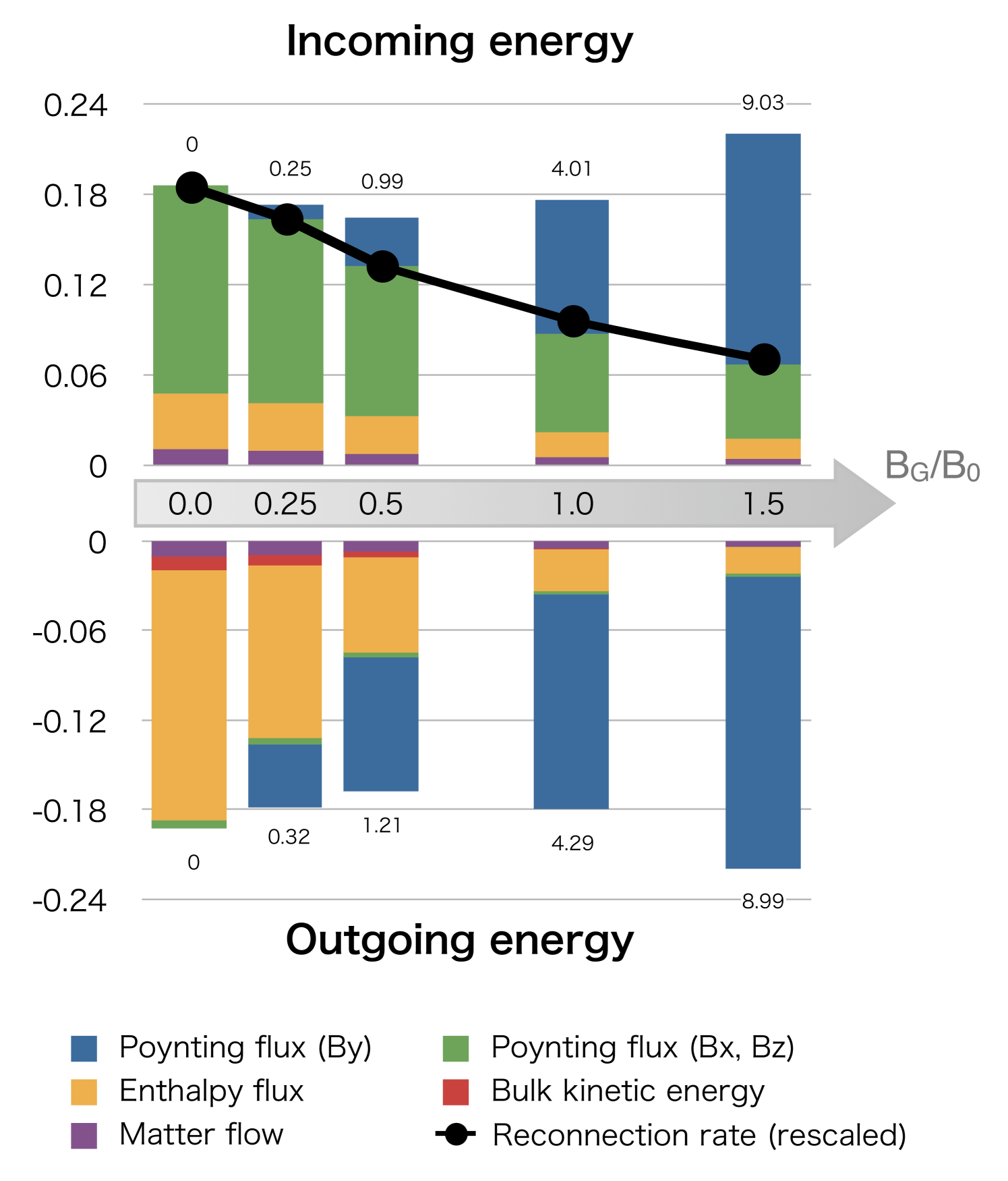
We consider the energy budget around the reconnecting square region of . The top panel in Figure 3 presents the composition of the incoming energy flux () per cross section at the inflow boundary () as a function of the guide field. They are normalized by the typical Poynting flux at the upstream border . The bottom panel in Figure 3 presents the outgoing energy flux () at the outflow boundary (), evaluated by the same unit as the upstream values. They are evaluated at the specific time steps in different runs, but they are carefully selected so that the energy budget becomes nearly steady in the rectangle region. We see that both two fluxes are well balanced. Although it may be difficult to recognize in the figure, the matter fluxes are also well balanced.
For comparison, rescaled values of reconnection rates (Table 1) are overplotted on the top panel in Figure 3. It is reasonable to see that they are proportional to the incoming energy flux except for -Poynting flux. The reconnection rate is relevant to the inflow speed , which transports the upstream antiparallel magnetic flux into the reconnected field . In these cases, under the similar upstream conditions, the -Poyting flux decreases as and the accompanying plasma flux also decreases accordingly. We also see that the reconnection rate decreases but it weakly depends on the guide field amplitude . This trend is consistent with a lot of previous nonrelativistic surveys (e.g., Huba (2005)).
We see that reconnection well dissipates the upstream antiparallel magnetic energy. When the guide field is weak, the Poynting energy is mostly converted into the plasma energy. Importantly, the energy is converted to the enthalpy flux rather than the bulk kinetic energy. The plasma pressure becomes strong in the outflow region in order to balance the strong upstream magnetic pressure. In magnetically dominated cases, plasma temperature becomes relativistic, and then such relativistic pressure substantially enhances the enthalpy flow. Therefore, the enthalpy flux dominates the bulk kinetic energy.
As the guide field increases, the relevant Poynting flux becomes a major component of the incoming energy flux. Simultaneously, the outgoing energy flux is dominated by the Poynting flux of the guide field. In the case of (run 3), as presented in Section 3.1, the guide field is compressed by a factor of . Consequently, the outgoing guide field Poynting flux increases and then it exceeds the enthalpy flux. When the guide field is stronger, the outflow is dominated by the Poynting flux by . In the outflow region, the ratio of the -Poynting flux to the plasma energy flux is , and , respectively. It is interesting to see that these ratios are similar to the initial upstream parameter (Table 1).
Under the single-fluid ideal RMHD approximation, we have the following relations from the polytropic law, the continuity, and the out-of-plane flux conservation:
| (14) |
where the prime sign (′) denotes the single-fluid properties. They immediately suggest that increases through the weak compression by magnetic reconnection,
| (15) |
In the case of run 3b, the typical compressional ratio of suggests that increases by a factor of . However, since our two-fluid system contains non-ideal effects, tends to reduce . In the stronger guide field cases, it is known that plasmas behave incompressibly and so the system is more likely to preserve .
3.4. Outflow channel
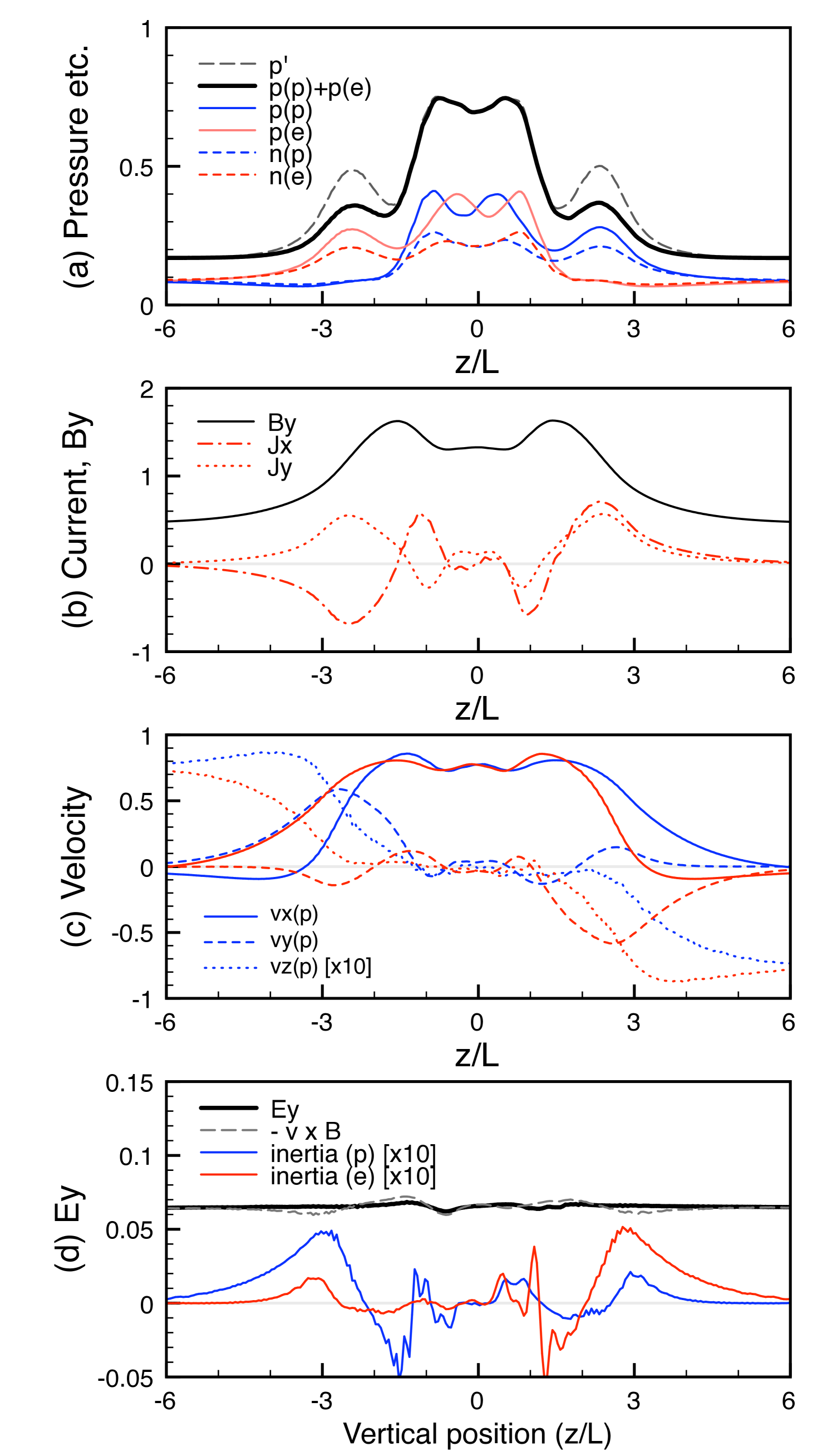
We look at the structure of the outflow region. Shown in Figure 4 are one-dimensional profiles across the outflow channel, at at . The cut line is indicated by a white line in Figure 1d. From these profiles, we see that the outflow region consists of three characteristic layers, separated by two peaks of : (1) a positron-rich boundary layer on the upper side (), (2) a central channel with high plasma pressure, and (3) an electron-rich boundary layer on the lower side.
The central channel contains a minor oscillating structure in plasma pressure (Figure 4a). Inside the central channel, the plasma temperature is hot and the outgoing fluid velocities are roughly similar across the channel. Since the Lorentz force works differently in the presence of the guide field , the positron and electron outflow channels are oppositely displaced to the -directions. The structures of the density, the pressure, the outflow speed , and the inflow speed (magnified 10 times larger in Figure 4c) are all consistent with the displacement of the flow channels. The central channel becomes wider in the further downstream and we confirm that the system keeps the three-layer structure at least .
We see that currents in the boundary layers are responsible for the global magnetic field topology. For example, explains the compression of the guide field , and a “bifurcated” -structure is consistent with the Petschek-type structure of in-plane magnetic fields (Figure 1d). We also see minor reverse currents near the center, but they are less important. Note that relative motion between the two species is significant in the boundary layers (Figure 4c), because plasmas sustain the currents in low-dense regions. Interestingly, in the upper positron-rich boundary layer, we see a fast electron flow in the -direction and indeed electrons are major contributors to there. This is because the Lorentz force modulates the local bulk outflow to the -direction, and so the electron flow looks overemphasized in our simulation frame.
In addition, in order to see the difference between our two-fluid model and the single-fluid RMHD model, we evaluate an equivalent single-fluid properties in the following way. We translate the conserved properties with the single-fluid properties (with the prime sign),
| (16) | |||||
| (17) | |||||
| (18) |
and then we calculate the single-fluid primitive variables by solving a quartic equation (Zenitani et al., 2009). The single-fluid pressure is assumed to be isotropic. Combining two fluid pressure into a single-fluid pressure does not lead to an isotropic pressure unless the relative velocity vanishes. The obtained pressure is overplotted in Figure 4a. We see that is in excellent agreement with the total two-fluid pressure in the central channel. On the other hand, the discrepancy is significant in the two boundary layers and so it may widen the outflow channel in single-fluid simulations. It is reasonable that the discrepancy is observed where the relative motion between the species is significant (Figure 4c).
In the boundary layers the local frozen-in condition also breaks down. We similarly analyze the composition of the reconnection electric field based on Equation 10. Figure 4d presents the profile of , along with the field convection and the -convection of fluid inertia terms,
| (19) | |||
| (20) |
In Figure 4d, the inertia terms are magnified 10 times larger to emphasize them. We found that the non-ideal contribution (the difference between and the term) is mostly explained by these terms. The positron inertial term appears in the lower electron-rich boundary layer, and electron term in the lower electron-rich layer. For example, in the positron-rich boundary region, both the -component of the positron velocity and the -momentum of the positrons are much smaller than that of the electrons. As a result, the electron inertial term dominates even though the positron density is larger. Around , the inertial contributions from both two fluids sustain 12% of . Because of the large Reynolds number , the frictional resistivity effect is negligible and we confirmed that the viscosity is negligible, too. Compared with the reconnection site where the nonideal terms are 100% responsible for the electric field, the nonideal effects are smaller, but they still play a role here.
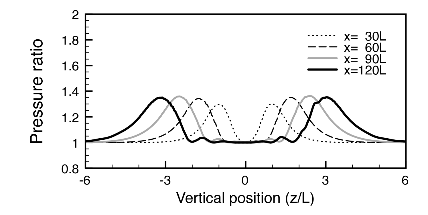
Shown in Figure 5 is the -dependence of the ratio of the single-fluid pressure () to the total fluid pressure (), which is a good measure of the two-fluid effects. As the central outflow channel expands downstream, the two-fluid effects are always localized in the relevant boundary regions. Their amplitude and spatial width are similar until the backward flows around the plasmoid hit the boundary layers.
4. DISCUSSION AND SUMMARY
Regarding basic models of antiparallel reconnections, there have been two controversial opinions on the relativistic reconnection rate. Blackman & Field (1994) argued that relativistic reconnection can involve relativistic inflow and the fast consumption of the upstream magnetic energy, because Lorentz contraction of the plasma outflow enables larger energy output per cross section. On the other hand, Lyubarsky (2005) pointed out that relativistic pressure increases an effective inertia , and that the shock balance condition allows a narrower Petschek outflow. Therefore, he argued that relativistic reconnection will not be an efficient energy converter, due to the slow outflow and the narrower energy output channel. Numerically, Zenitani et al. (2009) demonstrated that reconnection tends to be faster and faster in magnetically dominated regimes, although the obtained Petschek-type structure is best described by the Lyubarsky (2005) model. The unsolved problem is what makes reconnection faster, or what balances faster energy input?
In our energy balance analysis, we found that the outgoing plasma energy is mostly carried by the enthalpy flux or the internal pressure flux in the antiparallel case. We think this is an important reason why relativistic magnetic reconnection is faster. The plasma pressure in the outflow region needs to be relativistic in order to balance a strong upstream magnetic pressure (Lyubarsky, 2005). As the outflow plasma temperature becomes relativistically hot, we see that the enthalpy flux (pressure part) vastly exceeds the other parts by a factor of in the outflow channel. Since the enthalpy flux carries larger energy per cross section, the system can sustain faster energy input from the inflow region. In other words, the enthalpy flux is a key to sustaining fast reconnection.
The guide field introduced interesting changes to the reconnection structure. Since no process can annihilate the out-of-plane magnetic field, the inflows transport the upstream guide field to the narrow outflow region, and therefore the guide field is compressed inside the outflow channel. This significantly changes the energy composition in the reconnection outflow: the outgoing energy flow is rather dominated by the Poynting flux of the compressed guide field. Although there is no theoretical proof, our simulation results conserved (or slightly increased) the ratio of the -Poynting flux to the plasma energy . If we employ a principle of conservation, we can crudely estimate that the ratio of the upstream -Poynting flux to the downstream -Poynting flux and the downstream enthalpy flow is given by .
The boundary layers around the central reconnection jet exhibit a significant charge separation to retain the electric field system. The relative motion of species is significant in these layers, too. We think these conditions are beyond the scope of the single-fluid RMHD approach. The present resistive RMHD codes solve the charge distribution and the current , independently from plasma bulk motion. Such an approximation is valid when the charge separation and the relative motion are small. In fact, in the boundary layers, we pointed out that the single-fluid RMHD pressure and the two-fluid pressure differ by a factor of . We also note that Koide (2009) (see Section 7.1 for a summary) discussed the validity of generalized RMHD equations in detail. In our case of a pair plasma with relativistic pressure, the pressure condition () is weakly violated and the “proper charge neutrality” () breaks down in the boundary layers (Figure 4a).
We demonstrated that the fluid inertial effects are important to sustain magnetic reconnection in the reconnection region. This is a characteristic feature of the two-fluid model. By definition, a single-fluid RMHD model only takes care of the fluid bulk inertia, while it does not consider the inertial resistivity. The inertia effects violate the ideal MHD condition around the bifurcated boundary layers, too. In other words, inertial effects enhance an effective resistivity both in the reconnection region and near the discontinuities, playing a similar role as an anomalous-type resistivity. To mimic such physics, the nonrelativistic MHD simulations often employ resistivity profiles based on the electric current, for example, , but its relativistic extension may not be straightforward.
Using a single-fluid RMHD theory, Lyubarsky (2005) predicted that relativistic guide field reconnection involves a three-layer structure in the outflow region, with rotational discontinuities (outside) and slow shocks (inside). Furthermore, his balance analysis yielded that the outflow flux is dominated by the compressed guide field flux between the rotational discontinuities. In this work, we showed a different three-layer structure in the outflow region: the central hot outflow inside two charge-separated boundary layers. In our case, the rotational discontinuities cannot appear in the magnetically dominated upstream regions, because the system runs out of plasma to sustain the electric current. The upstream region does not have sufficient plasmas to sustain the charge separation for the vertical electric field , and therefore the -Poynting flux () is confined around the central dense channel. On the other hand, the other important prediction qualitatively holds true —the outward energy is dominated by the guide field Poynting flux. Energy transfer from the Poynting energy to the plasma energy will take place somewhere in the downstream edge, such as the interaction between plasmoids and the ambient medium.
In summary, we carried out full two-fluid simulations of relativistic magnetic reconnection with a guide field and investigated the characteristic properties, such as the charge separation and the guide field compression. We demonstrated that the guide field drastically changes the composition of the output energy flux, from enthalpy-dominated flow to Poynting-dominated flow, potentially controlled by . Inertial effects play a role of the effective resistivity, and so they violate an ideal frozen-in condition. Most importantly, we showed that the multi-fluid approach is very useful to study important relativistic plasma problems. It will be important to further study the consistency between the single-fluid RMHD model and the multi-fluid model.
References
- Abe & Hoshino (2001) Abe, S. A., & Hoshino, M. 2001, Earth Planets Space, 53, 663
- Blackman & Field (1994) Blackman, E. G., & Field, G. B. 1994, Phys. Rev. Lett., 72, 494
- Dedner et al. (2002) Dedner, A., Kemm, F., Kröner, D., Munz, C. D., Schnitzer, T., & Wesenberg, M. 2002, J. Comput. Phys., 175, 645
- Dumbser & Zanotti (2009) Dumbser, M., & Zanotti, O. 2009, J. Comput. Phys., 228, 6991
- Gurovich & Solov’ev (1986) Gurovich, V. Ts., & Solov’ev, L. S. 1986, Sov. Phys. JETP, 64, 677
- Hesse et al. (2004) Hesse, M., Kuznetsova, M., & Birn, J. 2004, Phys. Plasmas, 11, 5387
- Huba (2005) Huba, J. D. 2005, Phys. Plasmas, 12, 012322
- Jaroschek et al. (2004) Jaroschek, C. H., Treumann, R. A., Lesch H. & Scholer, M 2004, Phys. Plasmas, 11, 1151
- Koide (2009) Koide, S. 2009, ApJ, 696, 2220
- Komissarov (2007) Komissarov, S. S. 2007, MNRAS, 382, 995
- Lyubarsky (2005) Lyubarsky, Y. 2005, MNRAS, 358, 113
- Lyutikov & Uzdensky (2003) Lyutikov, M., & Uzdensky, D. 2003, ApJ, 589, 893
- Munz et al. (2000) Munz, C. D., Omnes, P., Schneider, R., Sonnendrücker, E., & Voß, U. 2000, J. Comput. Phys., 161, 484
- Palenzuela et al. (2009) Palenzuela, C., Lehner, L., Reula, O., & Rezzolla, L. 2009, MNRAS, 394, 1727
- Watanabe & Yokoyama (2006) Watanabe, N., & Yokoyama, T. 2006, ApJ, 647, L123
- Zenitani et al. (2009) Zenitani, S., Hesse, M., & Klimas, A. 2009, ApJ, 696, 1385
- Zenitani & Hoshino (2001) Zenitani, S., & Hoshino, M. 2001, ApJ, 562, L63
- Zenitani & Hoshino (2007) Zenitani, S., & Hoshino, M. 2007, ApJ, 670, 702
- Zenitani & Hoshino (2008) Zenitani, S., & Hoshino, M. 2008, ApJ, 677, 530