Robot Development and Path Planning for Indoor Ultraviolet Light Disinfection
Abstract
Regular irradiation of indoor environments with ultraviolet C (UVC) light has become a regular task for many indoor settings as a result of COVID-19, but current robotic systems attempting to automate it suffer from high costs and inefficient irradiation. In this paper, we propose a purpose-made inexpensive robotic platform with off-the-shelf components and standard navigation software that, with a novel algorithm for finding optimal irradiation locations, addresses both shortcomings to offer affordable and efficient solutions for UVC irradiation. We demonstrate in simulations the efficacy of the algorithm and show a prototypical run of the autonomous integrated robotic system in an indoor environment. In our sample instances, our proposed algorithm reduces the time needed by roughly 30% while it increases the coverage by a factor of 35% (when compared to the best possible placement of a static light).
1 Introduction
The new coronavirus has changed our world forever. Among the many lasting changes prompted by the rapid spread of SARS-CoV-2 is the need for regular systematic disinfection of indoor spaces, which has gone beyond hospitals and care facilities where room disinfection has always been a critical task that was performed on a regular basis (e.g., when patients were discharged) to public and private spaces such as schools, colleges, hospitality settings, airlines, train companies, and mass transportation authorities. In these spaces, regular disinfection will become a critical component of any strategy to reopen societies after a pandemic like the current one. However, this increases danger and time strain to the human workforce that is already stretched thin. Automating these processes is therefore an attractive approach. In the words of UVD Robots CEO Per Juul Nielsen, whose company builds robots with ultraviolet C (UVC) lights: “Hospitals around the world are waking up to autonomous disinfection. We can’t build these robots fast enough.”111www.forbes.com/sites/richblake1/2020/04/17/in-covid-19-fight-robots-report-for-disinfection-duty/
While solutions of this nature exist (see 2), there are three main shortcomings of the current solutions that severely limit their utility and applicability: (1) cost (the existing robots are very expensive, in some cases upwards of $100,000), (2) formal guarantees that every surface is disinfected, and (3) efficiency. It is unclear how well existing systems operate in part because of the lack of formal guarantees of the disinfection process.
In this paper, we address all three aspects with the design of an autonomous inexpensive custom robotic platform for UVC disinfection tasks. The robot can carry a significant payload, allowing it to operate for extended periods of time on battery power. More importantly, by finding close-to-optimal paths through the indoor space, the robot minimizes power use while guaranteeing that all surfaces receive sufficient light to guarantee disinfection.
2 Motivation and Related Work
Ultraviolet light irradiation has been used in health care settings for quite some time to deactivate contaminants. Initial studies suggested COVID-19 would be similar to other corona viruses [15], and studies have since confirmed the exact irradiation dose necessary to deactivate the virus (e.g., [13]).
Existing approaches are split between systems which are stationary in operation (e.g., Tru-D™ or [2]) and mobile platforms that have become a more frequent research focus: consider UVD Robots®, [12], [14], and other ongoing projects which have seen media coverage.222See Violet (time.com/5825860/coronavirus-robot/), work by Rovenso (spectrum.ieee.org/automaton/robotics/industrial-robots/rovenso-uv-disinfection-robot), or the ”ADAMMS-UV” from the USC Viterbi Center for Advanced Manufacturing, footnote 1. However, these platforms have either focused on the ability to bring a UVC lamp to a region rather than validating disinfection or have focused on proving disinfection experimentally rather than formally. See [16], [18], and [20] as examples of stationary options, and [17] as an example of a non-stationary option using a UVC wand.
Keeping devices stationary in a single location is suboptimal because light energy falls off with the square of the distance (see Section 4.2.1 for details) and the farthest surface point from the device is thus the determinant of the overall irradiation duration based on the minimum light exposure needed to deactivate the coronavirus.
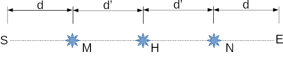
To see this, consider a UVC lamp placement in location , the halfway point, in the simplified 1D irradiation problem in Fig. 1. We assume the irradiation at all points long the line need to be at least 1. Consider sequential lamp placed in and such that the light intensity at the farthest points from the lamp at , , and is the same. Since and , we want to find and such that . The solutions are and and the overall irradiation time is , each in and in (since we have to irradiate sequentially, it would be if it were to be done in parallel with two lamps), a significant savings compared to .
In real-world settings there are additional difficulties: (1) 2D floor plans are more complex than the 1D approximation of a hallway provided and will therefore require more complex point placement (see Section 4), (2) robot navigation constraints will create point placement constraints, and (3) some obstacles may cause zones not reachable with direct light. Additionally, the example does not address movement time as a disinfection opportunity (the lamp can remain turned on while traveling through its environment), and additional challenges arise from operating in 3D with a platform only capable of moving in 2D. In this paper, we attempt to address (1), (2), and (3), while leaving the remainder for future work.
3 Low-Cost Robot Platform
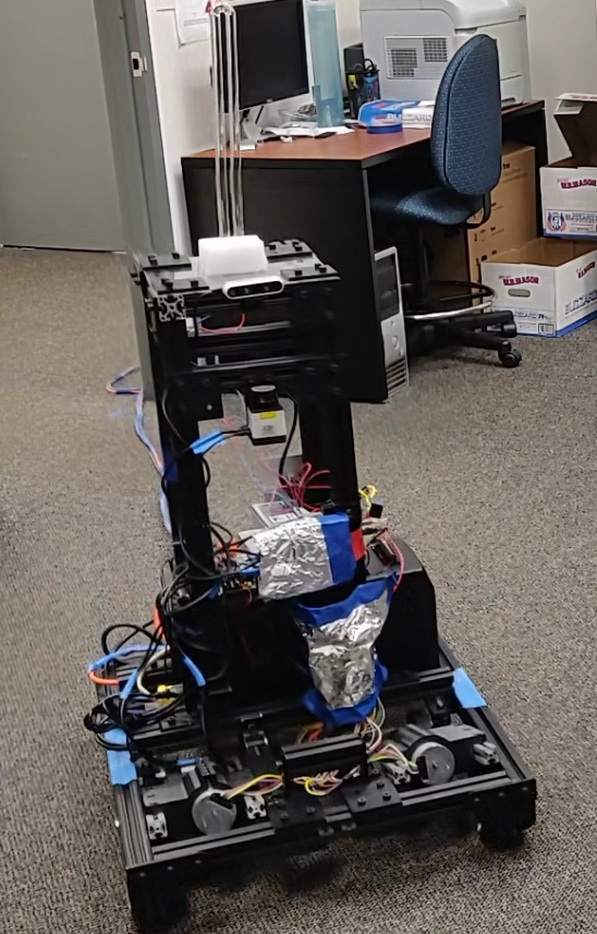
We developed a low-cost robotic platform equipped with an NVidia Jetson Nano embedded computing board for onboard computing (as outlined in Section 3.1) and a UVC germicidal lamp (which produces 17 Watts of UV-C radiation per 100 hours) for UVC disinfection. The robot is made of aluminium extrusion, with a square base of 24 by 28 inches. This is wide enough to provide stability for the pillar (which holds the lamp 34 inches above the ground) and space for the uninterruptible power supply (UPS) used for rechargeable power, while being thin enough to fit through a standard sized door.
Also mounted on the pillar are the robot’s sensors. Two LIDAR units (the Hokuyo URG 04LX) provide a 360-degree view of the environment, which was found to be necessary to address points which were close to obstacles by allowing the robot to safely reverse out of such spots. The Intel Realesense D435i provides a depth point cloud of the environment in front of the robot, allowing for obstacle avoidance of objects that may fall above or below the linear cloud collected by the LIDAR. Although the on-board IMU was initially used for odometery, this was found to be unnecessary due to the accuracy of the Canonical Scan Matcher (CSM) [3] which instead uses laser scan matching for odometery calculation.333We have used the CCNY ROS wrapping of CSM, available in the ROS scan_tools package.
The platform is differentially wheeled for the purposes of cost reduction. Additional stability is provided through passive omni-directional wheels in each corner. Both 4-inch polyurethane wheels interface with 24-volt brushless DC motors via drivers controlled over a USB-to-serial connection, and are on a spring-loaded mechanism to maintain contact with uneven surfaces. Brushless DC motors were chosen for their ability to produce high torque even at low speeds (necessary for the stop-and-go behavior of the heavy platform). Hall effect sensors attached to each commutator provide wheel rotation data, which is fed into the odometry calculations.
3.1 Navigation Software
The software running the robot is based on the Robot Operating System (ROS [19]) and utilizes standard mapping, control, and odometery packages in addition to some custom software packages for hardware control. Real-time path planning is performed using the ROS amcl package, which provides an implementation of works described in [22]. ROSControl [4] in conjunction with custom hardware code manages wheel velocities when attempting to complete a given trajectory. Mapping is performed using GMapping, which is described in [10, 11]. CSM [3] is used for odometry. The combination of these technologies enables basic obstacle-free waypoint navigation, which is required for the proposed algorithms for finding close-to-optimal disinfection paths described next.
4 Planning Paths for Disinfection
Our path planning algorithm receives the point cloud from the robot’s sensors. For tractability and modularity, we divide our algorithm into three independent pieces: (1) mapping (given point cloud data gathered by the robot, we obtain a floor plan of the building represented by a simple polygon); (2) waypoint and time determination (find locations and amount of time that the robot should stop and turn on the UVC light to so fully disinfect the floor); and (3) route planning (choose the order in which the waypoints are visited so as to minimize travel time).
Splitting the algorithm into independent subproblems may introduce additional error. In particular, the static placement of waypoints does not take into account the additional disinfection that may happen while the robot moves between waypoints. This error is proportional to the ratio between the amount of time spent moving and the time spent at the waypoints. For our application, this ratio is quite small (we spend hours at waypoints and a few minutes in motion). Thus, we believe that the overall error produced is negligible.
4.1 Mapping
Maps are generated through usage of a custom hardware platform (see Section 3). Laser scan data is converted into a 2D, top-down representation of the environment in which the robot can operate. The task of the mapping algorithm is to determine the location of a 2D curve that can approximate this occupancy grid. The curve represents the walls of the building (possibly with some furniture). Knowing the exact floor plan is critical in making sure that all locations of the room will be properly disinfected.
This problem is known as curve fitting or curve reconstruction in the literature (see the excellent survey by Dey in [6]). There are many approaches used to solve this problem. In our setting, the curve should follow the walls and possibly furniture of the room. A distinguishing feature from the general problem is that walls and furniture typically are rectangular.
As the sensors used are prone to noise caused by reflections, we preprocess the initial occupancy grid by performing a morphological closing to remove thin areas incorrectly labeled as free space. We then construct a polyline describing the room boundary from the occupancy grid using the algorithm described in [21] and implemented in OpenCV.
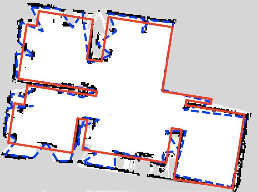
To reduce noise, we simplify the boundary. One standard simplification method, implemented in OpenCV, is the Douglas-Peucker algorithm [7]. However, we find that in some cases this works poorly on the scanned room data. Instead, we use the simplification algorithm described in [9] to find the best fit rectilinear polygon with the minimum number of vertices that remains within a specified tolerance of the original polygon. More precisely, we find the minimum area bounding rectangle of the unsimplified polygon to determine the directions of orthogonal compression, apply [9], and discard any self-intersections to simplify the boundary in linear time. Fig. 3 provides an example of an occupancy grid and the resulting approximation. Here, we find that using the rectilinear algorithm produces a very reasonable room boundary.
4.2 Waypoint selection
With the floor plan obtained from the mapping algorithm, we now focus on determining the waypoints—that is, we want to choose the specific places within the room that the robot should stop and turn the UVC light on to disinfect the room.
4.2.1 Modeling irradiation
Suppose we turn on the UVC Light at some point and are interested in how much energy is irradiated at a point . We measure amount of irradiation received with the following (standard) assumptions:
-
•
is irradiated by the light only if directly visible from (we do not consider reflection of light).
-
•
The intensity of the light received is proportional to the amount of time that the light is on and inversely proportional to the square of the distance between and .
-
•
If is at a wall, the intensity is also inversely proportional to the the incidence angle (i.e., vertical angle created between the normal vector of the wall containing and vector ). If is not at a wall, just extend the ray from to until it hits a wall to obtain the incidence angle.
We also assume that the UVC light is a single point whose height is halfway between the ceiling and the floor. This effectively allows us to transform the problem into a 2D one: the amount of irradiation received at the ceiling is the same as the irradiation received at the floor, and any other horizontal slice will receive more irradiation. Thus, as long as we sufficiently irradiate the ceiling or floor, we can guarantee full irradiation of the 3D volume.
This assumption is conservative: in practice, the light emanates from a lamp whose shape is similar to traditional fluorescent lamps (a vertical segment would be a more accurate representation). Light emanating from a segment would irradiate more since (i) it reduces the distance to and (ii) makes the incidence angle smaller. Thus, using a segment light increases the amount of irradiation received at .444An ideal placement would locate the light so that it is halfway from the floor and the ceiling. As we will see later, this has an impact on the shadow, but for now we ignore this.
With the above assumptions, we can model the amount of irradiation received at from in a unit of time as:
| (1) |
Here, is the incidence angle between and (see definition above), is a scaling constant (proportional to the intensity of the UVC light), denotes the 2D distance between and , and is half of the distance between the floor and ceiling. We say that a point is visible from a point if (1) the segment connecting the the two points does not intersect the polygon boundary, and (2) is larger than the shadow distance (i.e., the UVC light does not see the points directly below it). This shadow distance is based on some of the characteristics of the robot and the light source.
4.2.2 Waypoint selection as an LP problem
The above formula computes the irradiation from to for a single unit of time. In general, if the light is on for units of time, then would receive irradiation. Note that, for any fixed pair and , the amount of irradiation is proportional on the time that the robot spends there.
In order to make sure we fully disinfect the whole floor plan, we need to distinguish between the region we need to guard (the whole floor plan, denoted by ) and the areas within the room that we can reach (denoted by ). can be obtained by removing from all the points that are within a distance of an obstacle, where is the radius of the robot.
We apply a grid discretization of both regions by drawing horizontal and vertical lines that are units apart, partitioning and into grid cells. Let be the set containing the centers of all grid cells that lie within . We consider points of as potential waypoints for the robot.
We discretize in a similar fashion. This gives us a set of points that we need to guarantee that are disinfected. A point is disinfected if it has received enough irradiation (say, received at least units of irradiation).
This leads to a natural linear problem formulation: for any pair (waypoint, place to disinfect), measure how much is the point irradiated and accumulate over all possible waypoints. Globally, we want to minimize the time spent irradiating while at the same time make sure that all points are guarded.
Let be the time that we spent at waypoint . The waypoint selection problem is formalized as follows:
Note that because of the robot limitations, this often yields infeasible instances. This is simply because we would often have some corner of that is not seen by any point of . Thus, we remove from points that are not seen at all from . The percentage of points that need to be removed is also used as a measure of quality of the algorithm (the goal being disinfecting as close to of the room as possible). See Section 6 for more details.
The above formulation guarantees that all points of (visible from ) are disinfected, but even when all points of are visible, this does not guarantee that the whole room is disinfected. Indeed, when two consecutive grid points are seen by different waypoints we cannot guarantee that intermediate points are seen by either waypoint.
In the following, we provide two different modifications to the algorithm that would fix this issue.
4.2.3 Guaranteed disinfection
Our first approach modifies the definition of irradiance. We say that the “pessimistic irradiance” between a waypoint and a room point is the minimum irradiance between and any point in the grid cell containing . A feasible solution to the pessimistic irradiance LP problem will guarantee to disinfect, not only the discrete grid , but also the neighborhoods of all such points. By the construction of the grid cells, the union of all such neighborhood will be .
Alternatively, we can scale up the waiting times to guarantee that every point in the room receives the minimum level of irradiance. We locate the globally dimmest point in the room with respect to the waiting times and then compute a scale factor to ensure that point receives the minimum irradiance. Balakrishnan et al. [1] give a branch-and-bound algorithm for finding global minima using upper and lower bounds on the function’s minimum within a subregion of the search space. We find an upper bound on minimum irradiance in a region of a room by choosing an arbitrary point within the region and computing its irradiance. For a lower bound, we compute the pairwise irradiance between the guard points and vertices of the region, choose the minimum irradiance over the vertices for each guard point, and sum over the guard points. We use a triangulate-and-bound variant of Balakrishnan’s algorithm: we triangulate the room and split the triangles along their longest edge until, for each triangle, all vertices are covered by the same guard point (accounting for shadows if desired). For the branching procedure, we continue to split triangles in this manner. At the cost of a small decrease in coverage, we can achieve tighter bounds by allowing the removal of triangles with small areas or loose lower bounds from the search space.
Either of these two modifications guarantees that the visible region of the volume is disinfected. Walls of the region are also disinfected by the original LP formulation: while we only focus on disinfecting the lowest points along the wall, this is sufficient to disinfect the whole wall. Indeed, as distance and incidence angle are both maximized when the point is at the bottom of the wall, irradiance is minimized by points on the bottom of the wall. Thus, any solution that disinfects the bottom of the wall must also disinfect the entire wall.
It can be shown that as the discretization parameter approaches 0, the “pessimistic irradiance” algorithm converges to the minimum time needed to disinfect the room. The “branch-and-bound” algorithm converges in certain rooms, and we conjecture that it will perform reasonably in the general case.
4.3 Route planning
Once the waypoints (and stopping times for each of them) have been determined, we need to find an efficient way to visit all of them. This is a variation of the traveling salesman problem where weights are geodesics (i.e., the weight between any two points is the shortest paths within a simple polygon). We compute the geodesic distance between the waypoints by running Dijkstra, and then compute an approximation of the geodesic TSP that are available to the robot. In practice, the transport times are so small that they are overshadowed by the time spent at the waypoints.
In addition, we have to consider the orientation of the robot (i.e., it can only move forward in one specific direction, and whenever we need to change direction it must rotate). Good approximation solutions are known for these kind of problems, but unfortunately they run in exponential time [8]. The simpler solution used is to ensure waypoints do not place the robot too close to any obstacles (which is already being calculated) and to then allow the robot’s path planner determine the best way to get in and out of that position.
5 Evaluation Methods
We evaluate a solution by looking at (i) the percentage of the room that is disinfected555Some corners could not be disinfected in our instances while at the same time (ii) minimizing the time required to complete the disinfection. To establish a baseline for comparison, we propose a naive algorithm simulating a stationary disinfection routine: choose a single point near the center of 666Specifically, the midpoint of the largest segment of the horizontal bisector of the polygon. This is implemented in the representative_point function of the Shapely library and wait as long as necessary to completely disinfect the farthest point of the room that it can see. Since rooms are rarely starshaped, it will be unlikely that a single point will be able to guard the room. We expect this naive algorithm to perform terribly (in both of our optimization criteria); we mainly use it as a baseline for comparison purposes.
Note that our disinfection coefficient is fairly high compared to similar experiments. Note that in our experiments, a point must be irradiated with , which is a fairly high threshold (say, when compared to the threshold required in a similar experiment [16].). We do this because SARS-CoV-2 has been shown to be fairly resilient to irradiation [5]. In any case, we note that the value of the parameter itself has little impact on the results: coverage is unaffected, and a change in the coefficient would have a linear impact in time needed by both our baseline (stationary) and our algorithm.
We can also find an upper bound on the disinfection percent and a lower bound on the time required to achieve that percent for any path the robot can take. We use a similar idea to the “pessimistic irradiance” algorithm, applied in reverse: we consider the best possible irradiance possible between a point in the grid cell around the robot location and a point in the room. Define the “optimistic irradiance” between a point and a point to be the maximum irradiance between any point in the grid cell containing and the point . As the grid cells cover (ie. all possible locations the robot can be), running the linear program with “optimistic irradiance” constraints will produce an upper bound on the disinfection percentage and a lower bound on the disinfection time. As the discretization parameter approaches , these bounds tighten.
6 Experiments
| Algorithms that consider robot shadow | ||||||
|---|---|---|---|---|---|---|
| Branch & Bound | Pessimistic | Lower Bound | ||||
| Time | Disinf. | Time | Disinf. | Time | Disinf. | |
| (s) | % | (s) | % | (s) | % | |
| 1.0 | 112389 | 99.29 | 74804 | 91.54 | 17444 | 99.95 |
| 0.5 | 107893 | 95.10 | 58076 | 98.22 | 29434 | 99.90 |
| 0.3 | 88573 | 99.61 | 49211 | 99.14 | 29034 | 99.87 |
| 0.2 | 133928 | 99.60 | 39393 | 99.48 | 29935 | 99.85 |
| Algorithms that ignore robot shadow | ||||||
| Branch & Bound | Pessimistic | Lower Bound | ||||
| Time | Disinf. | Time | Disinf. | Time | Disinf. | |
| (s) | % | (s) | % | (s) | % | |
| 1.0 | 110969 | 99.29 | 57479 | 93.00 | 17444 | 99.95 |
| 0.5 | 107556 | 95.10 | 52921 | 98.47 | 29421 | 99.90 |
| 0.3 | 79854 | 99.61 | 47306 | 99.23 | 28812 | 99.87 |
| 0.2 | 132187 | 99.60 | 37734 | 99.48 | 29602 | 99.85 |
Naive Branch & Bound Pessimistic Irradiance Lower Bound Room Name Percent Percent Percent Percent Time (s) Disinfected Time (s) Disinfected Time (s) Disinfected Time (s) Disinfected HRI Lab 99937 41.65 133928 99.60 39393 99.48 29935 99.85 Room 2510 41403 85.15 200016 97.28 13546 98.60 12902 99.17 Room 2530 40845 94.19 35237 99.86 13958 99.22 16684 100.00 Room 2540777The “pessimistic irradiance” approach is unusually bad in this room due to a failure of the room boundary simplification algorithm, which in this case slightly exaggerates an obstacle and makes half the room inaccessable to the robot. 32228 58.07 79637 71.02 73654 72.20 67905 74.50 Room 2560 19066 57.88 31520 100.00 11854 100.00 7459 100.00 Room 2910 42857 84.74 12634 97.72 16323 98.18 9849 98.87
Six rooms were mapped and served as test data. We closely examine one room, the “HRI lab”, as a case study for the various parameters of the proposed algorithm. 888Code & data available at github.com/pjrule/covid-path-planning.
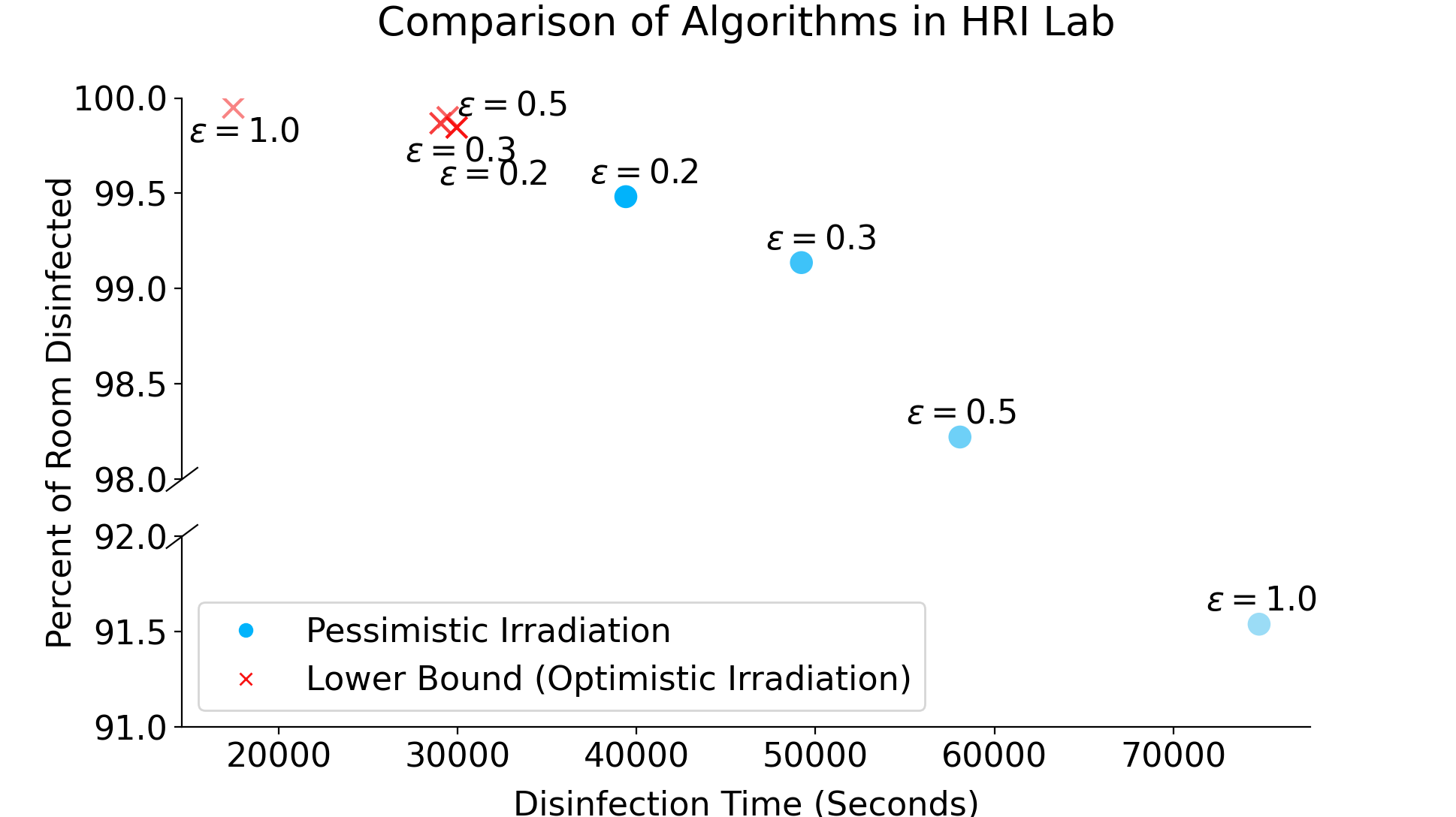
To establish a baseline we compute the amount of time that a stationary light would need when placed in the position that would maximize the coverage (i.e., disinfect the largest possible portion of the room). Just to give an example, a naive stationary solution (described in 5) yields a baseline disinfection time of seconds to disinfect of the room. A low disinfection percent is caused by the nonconvexity of the lab (i.e., walls and doors create many visibility constraints). Table 1 and Fig. 4 give a comparison between the two algorithms described in 4.2 and the lower bound described in 5, run with various values of the discretization parameter. Notice that as decreases, the solution times and disinfection percents achieved by the algorithms appear to quickly converge to the lower bound, as expected. The best solution time achieved is 2.5 times faster than the naive solution and disinfects twice as large an area. The branch-and-bound algorithm is competitive for some values of , though it is highly sensitive to parameterization and therefore does not always produce tight bounds. The data suggest the “pessimistic irradiance” algorithm often converges quickly to optimal; branch-and-bound appears to converge more slowly or not at all.
The effect of the robot’s shadow was also investigated. Due to the physical interference of the robot, the UVC light cannot disinfect the area directly below it. As this is the point where distance is minimized, one might worry that this negatively affects solution times. Table 1 shows the results of the simulations run for variations that consider or ignore the visibility. At , the solution accounting for robot shadow only takes longer than the solution that ignores shadow while disinfecting the same area: the effect is negligible.
Table 2 summarizes the performance of the various algorithms across all rooms at the discretization parameter . Similar to the case study, the “pessimistic irradiance” algorithm performs well relative to the lower bound and is a significant improvement over the naive approach.
6.1 Example run in the office environment
An example run of the algorithm fully integrated with a robotic platform is demonstrated 999Video of the demonstration can be found at https://hrilab.tufts.edu/movies/autonomous_disinfection.mp4. Exposure times are reduced to 1 second for succinctness.. First, the operator designates a zone to be disinfected by mapping it through teleoperation. When the operator is satisfied, the map can be reused for disinfection and path planning (assuming the environment does not drastically change).
Environment data inis provided to an implementation of the algorithm which produces the waypoints and exports them as location/time pairings in a CSV file. These pairings are read on startup of the robot software stack, and are referenced when the “begin disinfection” task is called. This task was triggered manually when testing, but scheduled approaches are also viable (assuming safety steps are taken to ensure no one is harmed by direct UVC exposure).
When the environment is ready for disinfection, the disinfection task is triggered and the robot moves to each point, ensuring that it remains at each point no less than the time specified by the algorithm. The light remains on between waypoints, because as outlined by 4 the error introduced by doing so is small and the consequences of additional exposure are more positive than negative.
The robot is placed just outside an empty pre-mapped office environment for which waypoints have been computed using the algorithm described, and then navigates into the room, turns on the lamp, and completes the loop specified by the waypoints. Some points were mapped as a result of being able to see them through glass doors, and so could not be navigated to: these points were removed for demonstration after having seen them handled sensibly (displaying an error but continuing to disinfect remaining achievable regions). To prevent accidental human UV-C exposure, the doors to the office are locked and labeled. The operator is in another room behind a closed door, which is where the robot tether leads for both power and monitoring purposes. All robot hardware and navigation control is handled on the platform.
7 Conclusion and Future Work
We have developed a low-cost autonomous robot platform together with a planning algorithm for UVC irradiation tasks and demonstrate effectiveness in simulation and hardware. While the current approach focused on using a floor plan for disinfection, future work will address the more difficult problem of computing the minimum necessary exposure time from 3D data, perhaps as a continuous path, which would allow the disinfection platform to use its travel time as disinfection time Additionally, improvements can be made to the platform, as the safety restrictions imposed as a result of COVID-19 impeded manufacturing and in turn forced design choices which could otherwise be avoided.
8 Acknowledgements
This project was funded in part by a Tufts COVID-19 Rapid Response Award. The authors would like to thank Diane Souvaine and the other members of the Computational Geometry laboratory at Tufts University for their suggestions and their helpful discussions.
References
- [1] V. Balakrishnan, S. Boyd, and S. Balemi. Branch and bound algorithm for computing the minimum stability degree of parameter-dependent linear systems. International Journal of Robust and Nonlinear Control, 1(4):295–317, 1991.
- [2] M. Bentancor and S. Vidal. Programmable and low-cost ultraviolet room disinfection device. HardwareX, 4:e00046, 2018.
- [3] A. Censi. An ICP variant using a point-to-line metric. In Proceedings of the IEEE International Conference on Robotics and Automation (ICRA), Pasadena, CA, May 2008.
- [4] S. Chitta, E. Marder-Eppstein, W. Meeussen, V. Pradeep, A. Rodríguez Tsouroukdissian, J. Bohren, D. Coleman, B. Magyar, G. Raiola, M. Lüdtke, and E. Fernández Perdomo. ros_control: A generic and simple control framework for ros. The Journal of Open Source Software, 2017.
- [5] J. G. B. Derraik, W. A. Anderson, E. A. Connelly, and Y. C. Anderson. Rapid evidence summary on sars-cov-2 survivorship and disinfection, and a reusable ppe protocol using a double-hit process. medRxiv, 2020.
- [6] T. K. Dey. Curve and surface reconstruction. In J. E. Goodman and J. O’Rourke, editors, Handbook of Discrete and Computational Geometry, Second Edition, pages 677–692. Chapman and Hall/CRC, 2004.
- [7] D. Douglas and T. Peucker. Algorithms for the reduction of the number of points required to represent a digitized line or its caricature. Cartographica: The International Journal for Geographic Information and Geovisualization, 10:112–122, 1973.
- [8] X. Goaoc, H. Kim, and S. Lazard. Bounded-curvature shortest paths through a sequence of points using convex optimization. SIAM J. Comput., 42(2):662–684, 2013.
- [9] A. Gribov. Searching for a compressed polyline with a minimum number of vertices. CoRR, abs/1504.06584, 2015.
- [10] G. Grisetti, C. Stachniss, and W. Burgard. Improved techniques for grid mapping with rao-blackwellized particle filters. IEEE Transactions on Robotics, 23(1):34–46, 2007.
- [11] G. Grisettiyz, C. Stachniss, and W. Burgard. Improving grid-based slam with rao-blackwellized particle filters by adaptive proposals and selective resampling. In Proceedings of the 2005 IEEE International Conference on Robotics and Automation, pages 2432–2437, 2005.
- [12] M. Guettari, I. Gharbi, and S. Hamza. Uvc disinfection robot. Environmental Science and Pollution Research, 2020.
- [13] C. S. Heilingloh, U. W. Aufderhorst, L. Schipper, U. Dittmer, O. Witzke, D. Yang, X. Zheng, K. Sutter, M. Trilling, M. Alt, E. Steinmann, and A. Krawczyk. Susceptibility of sars-cov-2 to uv irradiation. American Journal of Infection Control, 48:1273–1275, 2020.
- [14] A. Kreitenberg. Ultraviolet autonomous trolley for sanitizing aircraft, Dec. 9 2014. US Patent 8,907,304.
- [15] H. M., K. Hönes, P. Vatter, and C. Lingenfelder. Ultraviolet irradiation doses for coronavirus inactivation - review and analysis of coronavirus photoinactivation studies. GMS Hygiene and Infection Control, 15, 2020.
- [16] N. Mahida, N. Vaughan, and T. Boswell. First uk evaluation of an automated ultraviolet-c room decontamination device (tru-d™). Journal of Hospital Infection, 84(4):332 – 335, 2013.
- [17] M. M. Nerandzic, J. L. Cadnum, K. E. Eckart, and C. J. Donskey. Evaluation of a hand-held far-ultraviolet radiation device for decontamination of clostridium difficile and other healthcare-associated pathogens. BMC Infectious Diseases, 12(1):120, 2012.
- [18] M. M. Nerandzic, J. L. Cadnum, M. J. Pultz, and C. J. Donskey. Evaluation of an automated ultraviolet radiation device for decontamination of clostridium difficile and other healthcare-associated pathogens in hospital rooms. BMC Infectious Diseases, 10(1):197, 2010.
- [19] M. Quigley, K. Conley, B. Gerkey, J. Faust, T. Foote, J. Leibs, R. Wheeler, and A. Y. Ng. Ros: an open-source robot operating system. In ICRA workshop on open source software, volume 3, page 5. Kobe, Japan, 2009.
- [20] R. M. Ryan, G. E. Wilding, R. J. Wynn, R. C. Welliver, B. A. Holm, and C. L. Leach. Effect of enhanced ultraviolet germicidal irradiation in the heating ventilation and air conditioning system on ventilator-associated pneumonia in a neonatal intensive care unit. Journal of Perinatology, 31(9):607–614, 2011.
- [21] S. Suzuki and K. be. Topological structural analysis of digitized binary images by border following. Computer Vision, Graphics, and Image Processing, 30(1):32–46, 1985.
- [22] S. Thrun, W. Burgard, and D. Fox. Probabilistic robotics. MIT Press, Cambridge, Mass., 2005.