Secure multi-party quantum computation protocol for quantum circuits:
the exploitation of triply-even quantum error-correcting codes
Abstract
Secure multi-party quantum computation (MPQC) protocol is a cryptographic primitive allowing error-free distributed quantum computation to a group of mutually distrustful quantum nodes even when some quantum nodes disobey the instructions of the protocol. Here we suggest a modified MPQC protocol that adopts unconventional quantum error-correcting codes and as a consequence reduces the number of qubits required for the protocol execution. In particular, the replacement of the self-dual Calderbank-Shor-Steane quantum error-correcting codes with triply-even ones permits us to avoid the previously indispensable but resource-intensive procedure of the “magic” state verification. Besides, since every extra qubit reduces the credibility of physical devices, our suggestion makes the MPQC protocol more accessible for the near-future technology by reducing the number of necessary qubits per quantum node from , where is the security parameter, to .
I Introduction
As a well-established and widely used tool secure multi-party classical computation (MPCC) protocol allows classical nodes to jointly compute some publicly known function on their private inputs in a distributed manner Yao (1982). During the execution of the MPCC protocol cheating classical nodes, following the instructions of the protocol not honestly, cannot affect the output of the computation beyond choosing their inputs as well as cannot obtain any information on the inputs of the honest classical nodes beyond what they can infer from the output of the computation . Since the MPCC protocol allows for distributed computation of any function it becomes a powerful cryptographic primitive with many practical applications, e.g., secure electronic auction, secure electronic voting, and secure machine learning Evans et al. (2018).
Later developed more powerful quantum approach, secure multi-party quantum computation (MPQC) protocol, allows quantum nodes to jointly compute some publicly known quantum circuit on their private inputs Crépeau et al. (2002). In more detail, MPQC protocol can be described as a cryptographic primitive where each quantum node inputs some quantum state , and then quantum nodes jointly perform arbitrary quantum circuit with inputs and outputs. Finally, each quantum node obtains some output quantum state . See the schematic representation of the MPQC protocol in Fig. 1. Akin to its classical counterpart, the MPQC protocol satisfies the following informal requirements even in the presence of cheating quantum nodes:
-
•
Correctness and Soundness: Cheating quantum nodes cannot affect the outcome of the MPQC protocol beyond choosing their inputs.
-
•
Privacy: Cheating quantum nodes can learn nothing about the private inputs and outputs of the honest quantum nodes beyond what they can infer from the output of the computation.
Currently existing MPQC protocols developed for the quantum circuit model of computation can be divided into two types: information-theoretically secure ones Smith (2001); Crépeau et al. (2002); Ben-Or et al. (2006); Lipinska et al. (2020a); Goyal et al. (2022), meaning that there are no assumptions on the computational power of the cheating quantum nodes, and computationally secure ones Dupuis et al. (2010, 2012); Dulek et al. (2020); Alon et al. (2021); Bartusek et al. (2021); Huang and Tang (2022). The former type of the MPQC protocols is based on a technique of quantum error correction, which limits the maximum number of cheating quantum nodes to , i.e., a constraint inherent to the Knill-Laflamme bound or the so called quantum Singleton bound Knill and Laflamme (1997), while the latter type of the MPQC protocols is based on a technique of quantum authentication codes and can tolerate cheating quantum nodes.

In this paper, we consider the information-theoretically secure MPQC protocol which is based on a technique of quantum error correction. As a matter of fact, the technique of quantum error correction is tightly related to the concept of quantum secret sharing Cleve et al. (1999), the verifiable version of which was first suggested in Ref. Crépeau et al. (2002), and became a prevalent tool for constructing the information-theoretically secure MPQC protocols. In particular, following the approach taken in Refs. Lipinska et al. (2020a, 2022) we utilize the verifiable hybrid secret sharing (VHSS) protocol suggested in Ref. Lipinska et al. (2020b), i.e., a modified version of the original verifiable quantum secret sharing protocol presented in Ref. Crépeau et al. (2002). The VHSS protocol is rather versatile and works for any type of the Calderbank-Shor-Steane (CSS) quantum error correcting codes (QECCs) Steane (1996); Calderbank and Shor (1996). Therefore, at the beginning of the MPQC protocol, all the quantum nodes should agree on some CSS QECC with which they will remain until the end of the MPQC protocol.
At the highest level of abstraction, the MPQC protocol built upon a technique of quantum error correction and associated with it verifiable quantum secret sharing is executed in the following way. First of all, each quantum node encodes and shares his single-qubit input quantum state . In such a way, quantum nodes create a global logical quantum state shared among all the quantum nodes, and as a consequence, each quantum node holds a part of the global logical quantum state which we call a share. Next, quantum nodes jointly verify the encoding of each single-qubit input quantum state using the VHSS protocol Lipinska et al. (2020b). Then, quantum nodes locally perform quantum operations on their shares of the global logical quantum state to evaluate the logical version of the quantum circuit . Finally, each quantum node collects all the shares corresponding to his output from the other quantum nodes and by decoding these shares reconstructs his single-qubit output quantum state . Note that at this level of abstraction, our MPQC protocol follows the procedure of the previously suggested MPQC protocol in Refs. Lipinska et al. (2020a, 2022).
To implement the universal quantum computation (UQC) in the above MPQC protocol, a particular universal set of quantum gates need to be chosen. In addition, these quantum gates need to be transversal for a CSS QECC that is chosen at the beginning of the MPQC protocol. Specifically, this means that the application of local quantum operations to each share should yield a meaningful logical operation on the global logical quantum state. However, it is known to be impossible to implement an entire universal set of quantum gates transversally not only for the CSS QECCs but for any QECC Eastin and Knill (2009). Actually, the solution to this problem lies in the extension of the transversal set of quantum gates with a non-transversal quantum gate, which can be implemented for example by the gate teleportation technique, i.e., with the help of transversal quantum gates, local measurements, classical communication, and ancillary quantum state Gottesman and Chuang (1999).
In particular, the MPQC protocol suggested in Refs. Lipinska et al. (2020a, 2022) is based on a sub-class of CSS QECCs, i.e., self-dual CSS QECCs Steane (1996); Calderbank and Shor (1996) where the universal set of quantum gates is chosen to be the Clifford gates ( gate, gate, and gate) in combination with the gate Nebe et al. (2001), see Appendix D for definitions of the quantum gates. Self-dual CSS QECCs allow trivial implementation of the transversal Clifford gates but require additional techniques for implementation of the non-transversal gate. In case of the MPQC protocol originally suggested in Ref. Lipinska et al. (2020a) and later significantly reconsidered in Ref. Lipinska et al. (2022) one requires two additional techniques: the gate teleportation technique and the verification of the “magic” state technique, the latter of which is implemented by a statistical testing of the randomly selected “magic” states with their subsequent distillation 111In the original version of the MPQC protocol the verification of the “magic” state technique was implemented by the protocol called “verification of the Clifford stabilized states” (VCSS) which contained potential problems coming from the engagement of a non-transversal gate, see Appendix A and Appendix B.. Indeed, these additional techniques require an extra workspace for the implementation.
In this paper, we suggest an MPQC protocol constructed on the basis of triply-even CSS QECCs Betsumiya and Munemasa (2012); Knill et al. (1996), which constitute an another sub-class of general CSS QECCs Steane (1996); Calderbank and Shor (1996). In case of triply-even CSS QECCs, we decide on another universal set of quantum gates, i.e., gate, gate, gate, gate, and gate Chamberland and Jochym-O’Connor (2017), among which, triply-even CSS QECCs allow transversal implementation of gate, gate, gate, and gate while do not allow transversal implementation of the gate Knill et al. (1996). Therefore, in our MPQC protocol, a non-transversal gate is implemented by the gate teleportation technique, which has a lot of similarities with the implementation of the gate in Refs. Lipinska et al. (2020a, 2022). Nonetheless, the implementation of the non-transversal gate by the gate teleportation technique does not require verification of the ancillary logical “magic” state, i.e., whether it is certainly the logical “magic” state or not, see Ref. Lipinska et al. (2022) and Appendix C, since as an ancillary quantum state we need the logical “plus” state, i.e., a logical version of the single-qubit quantum state . Unlike the case of the logical “magic” state verification, the logical “plus” state can be easily verified by using the VHSS protocol only. Therefore, by avoiding the verification of the ancillary logical “magic” state we can reduce the workspace required for the implementation of the MPQC protocol from qubits in case of the previous suggestion, see Ref. Lipinska et al. (2022), to qubits in our case, where is the number of quantum nodes participating in the MPQC protocol and is the security parameter.
The paper is organized as follows. In Sec. II, we briefly overview our MPQC protocol. Then, in Sec. III, we declare our assumptions and definitions necessary for the construction of the MPQC protocol. We describe our assumptions on communication channels in Sec. III.1, and our assumptions on the properties of the adversary in Sec. III.2. In Sec. III.3, we define properties common to any type of CSS QECCs, and in Sec. III.4, we discuss a sub-class of general CSS QECCs called triply-even CSS QECCs. Subsequently, in Sec. IV, we outline all the subroutines involved in the MPQC protocol: the VHSS protocol in Sec IV.1 and the gate teleportation protocol in Sec. IV.2. After that, in Sec. V, we present a detailed outline of our MPQC protocol. Next, in Sec. VI, we prove the security of our MPQC protocol. In particular, we begin with stating the security framework as well as the security definition of our MPQC protocol in Sec. VI.1, and then we find that the security proof of our MPQC protocol should be identical to the previously suggested MPQC protocol in Sec. VI.2. Moreover, to be self-contained, we briefly present the security proof of our MPQC protocol in Secs. VI.2.2 and VI.2.1. Finally, Sec. VII is devoted to the summary.
II Summary of the MPQC protocol
| Input: Single-qubit quantum state from each quantum node , agreement on a particular , and a particular . |
| Output: In case of success, single-qubit quantum state in the possession of each quantum node . In case of failure, i.e., excess in the number of cheating quantum nodes, the MPQC protocol is aborted at the end of the computation. |
| 1. Sharing: By encoding and sharing each of the inputs twice, quantum nodes create a global logical quantum state where each quantum node holds a share . For the details see Sec. IV.1. 2. Verification: All the quantum nodes jointly verify the encoding of each input with the help of the VHSS protocol to check whether each quantum node is honest or not. For the details see Sec. IV.1. 3. Computation: Depending on whether the quantum gate appearing in can be implemented transversally or not, or whether the implementation of the requires an ancillary quantum state, quantum nodes behave in the following three ways: (a) In case of the transversal quantum gates, i.e., gate, gate, gate, or gate, each quantum node locally applies corresponding quantum operations to his share . (b) In case of the non-transversal gate applied to the quantum wire of the , quantum nodes jointly prepare verified by the VHSS protocol ancillary logical quantum state created from the single-qubit quantum state , and then perform the gate teleportation technique. For the details see Sec. IV.2. (c) In case the implementation of the requires an ancillary quantum state, quantum nodes jointly prepare verified by the VHSS protocol ancillary logical quantum state created from the single-qubit quantum state . 4. Reconstruction: Each quantum node collects all the single-qubit quantum states corresponding to his output and by decoding in such a way obtained output logical quantum state twice, reconstructs his output . For the details see Sec. IV.1. |
Here we briefly describe our MPQC protocol. In a similar manner to Refs. Crépeau et al. (2002); Smith (2001); Lipinska et al. (2020a, 2022), our MPQC protocol is based on a technique of quantum error correction, or to be more specific, on the concept of quantum secret sharing Cleve et al. (1999), and in particular utilizes the VHSS protocol suggested in Ref. Lipinska et al. (2020b) as its building block. The VHSS protocol works for any type of CSS QECCs encoding single-qubit quantum states into -qubit logical quantum states, see Sec. IV.1. Therefore, in our MPQC protocol the input quantum states and the output quantum states will indeed be single-qubit quantum states. In particular, our construction of the MPQC protocol relies on a sub-class of general CSS QECCs Steane (1996); Calderbank and Shor (1996), see Sec. III.3, i.e., triply-even CSS QECCs Betsumiya and Munemasa (2012); Knill et al. (1996), see Sec. III.4. In fact, triply-even CSS QECCs allow transversal implementation of gate, gate, gate, and gate while do not allow transversal implementation of the gate, and to implement the non-transversal gate we utilize the gate teleportation technique as will be explained below, see Sec. IV.2.
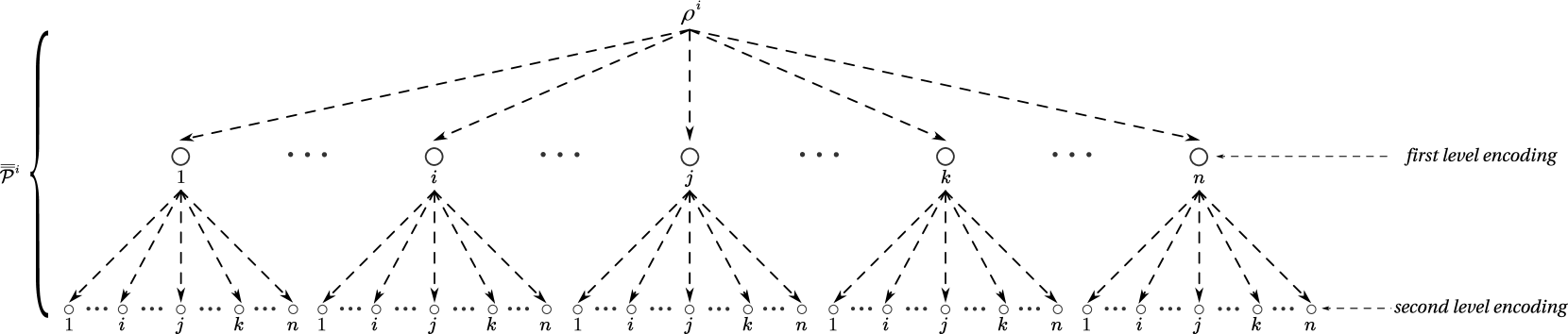
At the beginning of the MPQC protocol, quantum nodes should agree on a particular triply-even CSS QECC described above and then create global logical quantum state by encoding and sharing each of the inputs twice, see Fig. 2. Hereafter, the double bar always means that the quantum state is encoded twice. As a result, each quantum node holds a part of the global logical quantum state , i.e., a share denoted as . Next, to check whether each quantum node is honest or not, quantum nodes jointly verify the encoding of each input by using the VHSS protocol Lipinska et al. (2020b), see Sec. IV.1. After that, quantum nodes jointly evaluate logical quantum circuit , i.e., a twice encoded version of the quantum circuit , see Sec. V. Here, in case of the transversal quantum gates, each quantum node locally performs necessary quantum operations on his share . On the other hand, in case of non-transversal quantum gates, quantum nodes jointly perform the gate teleportation technique, see Sec. IV.2. In addition, if the implementation of the logical quantum circuit requires an ancillary quantum state, quantum nodes jointly create the ancillary logical quantum state by encoding and sharing a single-qubit quantum state twice. Finally, each quantum node collects all the single-qubit quantum states corresponding to his output from the other quantum nodes and by decoding in such a way obtained output logical quantum state twice, eventually reconstructs his output , see Sec. IV.1. Also, during the execution of the MPQC protocol quantum nodes publicly record the positions of the cheating quantum nodes to decide whether to abort the MPQC protocol or not. In particular, information on the positions of the cheating quantum nodes is updated each time the VHSS protocol or the gate teleportation protocol is invoked.
In short, the gate teleportation technique implementing a non-transversal gate, where superscript means that the quantum gate is applied to the quantum wire of the quantum circuit , is performed as follows. Suppose quantum nodes want to apply a non-transversal gate, i.e., a logical version of the non-transversal gate, applied to the part of the global logical quantum state initially created from the single-qubit input quantum state and denoted as . Quantum nodes jointly prepare verified by the VHSS protocol ancillary logical quantum state created from a single-qubit quantum state . Then, with the help of transversal quantum gates, local measurements, and classical communication, quantum nodes apply non-transversal gate to the logical quantum state , or in other words, achieve the realization of the logical quantum state , see Fig. 4. During the gate teleportation protocol information on the positions of the cheating quantum nodes is updated, see Sec. IV.2 for details.
We note that our MPQC protocol is information-theoretically secure, i.e., we make no assumptions on the computational power of the non-adaptive active adversary, see Sec. III.2, but has an exponentially small probability of error inherited from the VHSS protocol, i.e., , where is the security parameter and , with standing for the number of ancillary quantum states required for the implementation of the quantum circuit and standing for the number of the gates 222Namely, is equal to the number of times the VHSS protocol is invoked during the execution of the MPQC protocol.. Also, the aforementioned adversary in our MPQC protocol is limited only by the number of quantum nodes it can corrupt, see Sec. III.2, which is a limitation derived from the Knill-Laflamme bound or the quantum Singleton bound Knill and Laflamme (1997), see Ref. Smith (2001) for details. To be more specific, the number of corrupted quantum nodes is constrained by the distance of the triply-even CSS QECC as , see Sec. III.3. This constraint allows honest quantum nodes to correct all the arbitrary quantum errors introduced by the cheating quantum nodes. Consequently, our MPQC protocol satisfies the security requirements, i.e., correctness, soundness, and privacy, which indeed hold with the probability exponentially close to in the security parameter , see Sec. VI. Important to note that we allow our MPQC protocol to abort at the end of computation if honest quantum nodes detect too many cheating quantum nodes during the execution of the protocol, in a similar manner to Refs. Lipinska et al. (2020a, 2022).
During the execution of the MPQC protocol, in addition to the single-qubit quantum states required for holding a share , each quantum node uses single-qubit ancillary quantum states to verify the encodings of the inputs by the VHSS protocol, see Sec. IV.1, and single-qubit ancillary quantum states to apply a non-transversal gate with the gate teleportation technique involving verification of the ancillary logical quantum state , see Sec. IV.2, or to verify the ancillary logical quantum states which may be required for the implementation of the logical quantum circuit . Thus, in total each quantum node requires qubits for the implementation of the MPQC protocol. Finally, since the communication complexity of the VHSS protocol per quantum node is qubits, see Sec. IV.1, the communication complexity of our MPQC protocol per quantum node will be qubits, see Sec. V, which is proportional to the total number of the VHSS protocol executions during the MPQC protocol.
III Assumptions and Definitions
In this section, we overview our assumptions and definitions necessary for the construction of the MPQC protocol. In Sec. III.1, we describe our assumptions on the classical and quantum communication channels as well as on the broadcast channel, and in Sec. III.2, we describe our assumptions on the adversary. Next, in Sec. III.3, we define properties common to any type of CSS QECCs, and finally, in Sec. III.4, we discuss a sub-class of CSS QECCs, i.e., triply-even CSS QECCs.
III.1 Communication channels
In our MPQC protocol, we assume that all the quantum nodes have an access to the classical authenticated broadcast channel Canetti et al. (1999) (which is feasible if and only if Lamport et al. (1982); Pease et al. (1980)) and to the public source of randomness, the latter of which can be created with the help of the secure multi-party classical computation Ben-Or et al. (1988); Chaum et al. (1988) (which is also feasible if and only if ) 333We note that aforementioned constraints on the feasibility of the classical authenticated broadcast channel and the public source of randomness do not cause any additional problems since we assume that only quantum nodes are corrupted by the adversary, see Sec. III.2.. Also, each pair of quantum nodes is connected via the authenticated and private classical Canetti (2004) and quantum Barnum et al. (2002) channels. Finally, we assume that each quantum node can perfectly process and store classical and quantum information.
III.2 Adversary
In our MPQC protocol, we make no assumptions about the computational power of the adversary. Our non-adaptive 444Non-adaptive is the adversary that chooses quantum nodes to corrupt before the MPQC protocol begins and remains with that choice., but active 555Active is the adversary that is able to perform arbitrary quantum operations on the shares in the possession of the corrupted quantum nodes. adversary is limited only by the number of quantum nodes it can corrupt. The quantum nodes which are corrupted by the adversary and therefore disobey the instructions of the MPQC protocol are called cheating quantum nodes. On the contrary, the quantum nodes which are not corrupted by the adversary and obey the instructions of the MPQC protocol are called honest quantum nodes.
III.3 CSS QECCs
Since in our MPQC protocol we consider a sub-class of general CSS QECCs Steane (1996); Calderbank and Shor (1996), i.e., triply-even CSS QECCs Betsumiya and Munemasa (2012); Knill et al. (1996), we first define properties common to any type of CSS QECCs. Hereafter, stands for the distance binary classical linear code that encodes bits into bits. General CSS QECC is defined through the two binary classical linear codes denoted as and , and these binary classical linear codes satisfy the following three conditions:
-
•
is an binary classical linear code that can correct bit errors.
-
•
is an binary classical linear code that can correct bit errors.
-
•
and satisfy , where means the dual of the binary classical linear code . Here, is an classical linear code that satisfies .
These two binary classical linear codes generate an CSS QECC encoding -qubit quantum state into -qubit logical quantum state, and where the constraint is satisfied. Such a CSS QECC can correct bit flip () errors and phase flip () errors, which leads to a CSS QECC with distance tolerating arbitrary quantum errors and erasure quantum errors.
Since the VHSS protocol we employ in this paper works for any type of CSS QECCs encoding single-qubit quantum states into -qubit logical quantum state, see Sec. IV.1, will always be equal to , and therefore the encodings of the standard basis “zero” state and the Fourier basis “plus” state can be written as and correspondingly. Here individual codewords of the binary classical linear codes and are denoted as and respectively.
Important to note that a CSS QECC generated by the two binary classical linear codes and may be denoted as a set (where stands for the Fourier transform), which means that a CSS QECC is a set of -qubit logical quantum states, which yield a codeword in when measured in the standard basis (also called basis in the literature) and a codeword in when measured in the Fourier basis (also called basis in the literature) Nielsen and Chuang (2011).
Also, we emphasize that any type of CSS QECC allows transversal implementation of the gate, while not any type of CSS QECC allows transversal implementation of the other well-known quantum gates such as gate, gate, or gate. For example, a sub-class of general CSS QECCs constructed from the two binary classical linear codes satisfying and called self-dual CSS QECCs Preskill (1999), allows transversal implementation of gate, gate, and gate, while does not allow transversal implementation of the gate. Besides, we should note that in case of CSS QECCs, logical measurement can be implemented transversally by local measurements of all the single-qubit quantum states comprising the -qubit logical quantum state and the classical communication.
Finally, let us mention the important property of CSS QECCs. The set of stabilizer generators of any CSS QECC can be divided into the set of stabilizer generators consisting of only and (in this case, each stabilizer generator is denoted as and the entire set is denoted as ) or only and (in this case, each stabilizer generator is denoted as and the entire set is denoted as ) operators in the tensor product representation, which permits independent correction of the bit flip () and the phase flip () errors. As it happens, the Steane-type quantum error correction method Steane (1997) on the basis of which the VHSS protocol is built, takes advantage of this fact Lipinska et al. (2020b), see Sec. IV.1 for details. Furthermore, the encoding of the standard basis “zero” state and the Fourier basis “plus” state in terms of the stabilizer generators can be written as and correspondingly.
III.4 Triply-even CSS QECCs
To be comprehensive, we briefly describe a method of constructing the triply-even CSS QECCs Betsumiya and Munemasa (2012); Knill et al. (1996), which constitute a sub-class of general CSS QECCs Steane (1996); Calderbank and Shor (1996) and allow transversal implementation of the gate without any Clifford corrections Rengaswamy et al. (2020). This is in contrast to the so called triorthogonal CSS QECCs, which constitute an another sub-class of general CSS QECCs as well as comprise a super-class for the triply-even CSS QECCs , and for which the transversal implementation of the gate requires additional Clifford corrections Bravyi and Haah (2012). We begin with the definition of the triply-even binary matrices Betsumiya and Munemasa (2012) from which the triply-even CSS QECCs can be constructed Paetznick (2014). Suppose the existence of two binary vectors , with the Hamming weights and respectively, and for which the entry-wise product is defined. In this case, we call an binary matrix triorthogonal if for its rows following two conditions are satisfied:
| (1) |
for all triples of rows ,
| (2) |
for all pairs of rows . If in addition to the above two conditions the more restrictive constraint
| (3) |
is satisfied for all pairs of even weight rows , we call the binary matrix triply-even. The latter constraint implies that is satisfied for all the even weight rows of the binary matrix Paetznick (2014). Important to note that we assume the binary matrix consisting of two submatrices: the one comprised of even weight rows and denoted as (an matrix) and the one comprised of odd weight rows and denoted as (an matrix).
With the above triply-even binary matrix at hand, one can construct corresponding triply-even CSS QECC as follows Bravyi and Haah (2012); Paetznick (2014). For each row of the binary matrix , one defines an stabilizer generator by mapping non-zero entries of the row to the operators (and zero entries of the row to the operators). Next, for each row of the orthogonal complement of the triply-even binary matrix , i.e., , one defines a stabilizer generator by mapping non-zero entries of the row to the operators (and zero entries of the row to the operators). Finally, each row of the binary matrix corresponds to both the and operators, if non-zero entries of the rows are mapped to the and operators respectively (and zero entries of the rows to the operators in both cases).
Let us also mention about the minimum distance of the triply-even CSS QECCs constructed above. If we denote the linear span of all the rows of the binary matrices () and as () and respectively, in case of the triorthogonal CSS QECCs, and consequently the triply-even CSS QECCs , the condition is satisfied and this fact will automatically imply the relation , where and mean the distances against the phase flip and bit flip errors respectively Bravyi and Haah (2012); Paetznick (2014). Therefore, the minimum distance of the triply-even CSS QECC can be defined as the minimum weight of any non-trivial operator: Bravyi and Haah (2012); Nezami and Haah (2022).
Eventually, to introduce an essential property of the triply-even CSS QECCs , i.e., a transversal implementation of the gate without any Clifford corrections, we define the weight of a stabilizer generator as the number of terms not-equal to in the tensor product representation. Actually, according to the Ref. Rengaswamy et al. (2020), a CSS QECC allows transversal implementation of the gate without any Clifford corrections if and only if the binary matrix is triorthogonal, i.e., Eqs. 1 and 2 are satisfied, and the weight of all the stabilizer generators is multiple of eight: 666This statement is indeed consistent with the claim that the condition is satisfied for all the even weight rows of the triply-even binary matrix .. An example of such a CSS QECC is CSS QECC Knill et al. (1996), as well as CSS QECC Bravyi and Haah (2012).
As we can see from the above discussions, triply-even CSS QECCs allow transversal implementation of gate, gate, gate (since any type of CSS QECC allows transversal implementation of these quantum gates), and gate. Therefore, only the gate in the chosen universal set of quantum gates ( gate, gate, gate, gate, and gate) is not transversal and needs to be implemented by the gate teleportation technique, see Sec. IV.2, since in case of the triply-even CSS QECCs binary classical linear codes and do not satisfy .
IV Subroutines of the MPQC protocol
In this section, we describe subroutines used as building blocks in the construction of the MPQC protocol. In Sec. IV.1, we review the VHSS protocol used during the sharing, verification, and reconstruction phases of the MPQC protocol, and in Sec. IV.2, we outline the gate teleportation technique necessary for the implementation of the gate, which is non-transversal in case of triply-even CSS QECCs used in our construction of the MPQC protocol.
IV.1 Outline of the VHSS protocol

| Input: Private single-qubit quantum state (or , ) from the dealer and an agreement on a particular . |
| Output: At the end of the verification phase, each quantum node holds a share (or , ) of the jointly verified logical quantum state (or , ) (and if required, quantum nodes are also able to confirm that what they hold is definitely a logical quantum state , ) and a public set . |
| 1. Sharing: Quantum nodes jointly create logical quantum state (or , ) by encoding and sharing input (or , ) among all the quantum nodes. At the end of the sharing phase, each quantum node holds single-qubit quantum states coming from every other quantum node. (a) Dealer encodes his input (or , ) into the -qubit logical quantum state by using and shares it among all the quantum nodes (including himself). We call this procedure the first level encoding. (b) Then, each quantum node one more time encodes a single-qubit quantum state obtained from the dealer into the -qubit logical quantum state by using and shares it among all the quantum nodes (including himself). We call this procedure the second level encoding. 2. Verification: Quantum nodes jointly verify that the input (or , ) from the dealer is properly encoded and shared, and the valid logical quantum state (or , ) is created. Let us call this procedure as verification of . Also, if required, quantum nodes jointly confirm that the input from the dealer is exactly (). Let us call this procedure as confirmation of (). (a) Verification of : Quantum nodes create ancillary logical quantum states and with the same method as they created logical quantum state in the sharing phase, propagate arbitrary quantum errors (if any) in the logical quantum state to these ancillary logical quantum states, logically measure them in the appropriate basis, and decode the results of these logical measurements to find arbitrary quantum errors in the logical quantum state (if any). (b) Confirmation of (): Quantum nodes create ancillary logical quantum states () with the same method as they created logical quantum state in the sharing phase, propagate arbitrary quantum errors (if any) in the logical quantum state () to these ancillary logical quantum states, and logically measure them in the standard (Fourier) basis. Finally, quantum nodes decode the results of the logical measurements and publicly check whether they correspond to the (). (c) During the verification phase, quantum nodes jointly construct a public set , which records all the arbitrary quantum errors introduced by the dealer and by the cheating quantum nodes. (d) If at the end of the verification phase is satisfied, the dealer passes the verification phase, and the VHSS protocol continues to the reconstruction phase. On the other hand, if is satisfied the VHSS protocol aborts. 3. Reconstruction: Reconstructor performs the following quantum operations on the single-qubit quantum states collected from the other quantum nodes and at the end of the reconstruction phase obtains output . (a) Reconstructor identifies all the arbitrary quantum errors in each -qubit logical quantum state originally encoded and shared by the quantum node , by using . After that, the reconstructor decodes all the -qubit logical quantum states with arbitrary quantum errors. This is the second level decoding. Otherwise, the reconstructor adds quantum node to the public set . (b) From the single-qubit quantum states obtained during the second level decoding, the reconstructor randomly chooses single-qubit quantum states, each originally encoded and shared by the quantum node , performs erasure recovery by using and by decoding obtains output . This is the first level decoding. |
An important ingredient required for the construction of our MPQC protocol based on a technique of quantum error correction is the VHSS protocol, which was recently introduced in Ref. Lipinska et al. (2020b). First of all, quantum nodes participating in the MPQC protocol use the VHSS protocol to encode and share a single-qubit input quantum state among all the quantum nodes in a verifiable way. We note that the VHSS protocol in Ref. Lipinska et al. (2020b) is applicable to any type of CSS QECC and that if the minimum distance of the underlying CSS QECC is , the VHSS protocol tolerates cheating quantum nodes corrupted by the adversary described in Sec. III.2. As it was already mentioned in Sec. II, this constraint indeed allows honest quantum nodes to correct all the arbitrary quantum errors introduced by the cheating quantum nodes. To be more specific, the VHSS protocol is information-theoretically secure and satisfies the security requirements, i.e., soundness, completeness, and secrecy, which hold with the probability exponentially close to in the security parameter . Namely, the verification performed by using the VHSS protocol has the probability of error . The detailed security proof can be found in Ref. Lipinska et al. (2020b).
First, let us describe the VHSS protocol itself. In the sharing phase of the VHSS protocol, some quantum node acting as a dealer encodes his input into the -qubit logical quantum state by using some CSS QECC (some triply-even CSS QECC in our case) on which all the quantum nodes have an agreement and shares it among all the quantum nodes (including himself). We call this procedure the first level encoding. Then, each quantum node one more time encodes a single-qubit quantum state obtained from the dealer into the -qubit logical quantum state by using the same CSS QECC (the same triply-even CSS QECC in our case) and one more time shares it among all the quantum nodes (including himself). We call this procedure the second level encoding. Eventually, quantum nodes jointly possess logical quantum state (or global logical quantum state if all the quantum nodes participating in the MPQC protocol have finished the sharing phase of the VHSS protocol), see Fig. 2.
In the verification phase of the VHSS protocol, quantum nodes jointly verify that the quantum state in their possession is for sure a valid logical quantum state encoded by the aforementioned triply-even CSS QECC . To be more specific, quantum nodes publicly check that there are arbitrary quantum errors introduced by the dealer during the procedure of the first level encoding, which will also mean that the dealer is honest. For that purpose, first, quantum nodes jointly prepare ancillary logical quantum states (to detect the phase flip errors) or (to detect the bit flip errors), which are generated in the same way as the logical quantum state but from the single-qubit input quantum states or respectively. Then, quantum nodes propagate arbitrary quantum errors in the logical quantum state (if any) to these ancillary logical quantum states by means of the transversal application of the gate (superscript means that the logical quantum gate is applied between the logical quantum states initially created from the single-qubit input quantum states , , or ) to their shares. Next, quantum nodes logically measure the ancillary logical quantum states in the appropriate basis, and finally, by decoding the results of these logical measurements find arbitrary quantum errors in the logical quantum state (if any). The detailed procedure of the bit flip errors detection is shown in Fig. 3.
Actually, the above procedure is an extension of the Steane-type quantum error correction method introduced in Ref. Steane (1997) and stands for a single iteration in the verification phase of the VHSS protocol which contains of such iterations. To be more specific, there are iterations to check the bit flip errors (where each iteration spends single ancillary logical quantum state ), iterations to check the phase flip errors (where each iteration spends single ancillary logical quantum state ), and additional iterations for each ancillary logical quantum state to check it for the bit flip errors (where each iteration indeed spends single ancillary logical quantum state ). Obviously, this procedure requires a workspace of qubits per quantum node, i.e., a workspace of qubits per quantum node for each of the logical quantum states , , and , which need to be stored simultaneously during the verification phase of the VHSS protocol, see Ref. Lipinska et al. (2020b) for the details.
Throughout the verification phase of the VHSS protocol, quantum nodes jointly construct a public set of apparent cheaters , which records all the arbitrary quantum errors introduced by the dealer during the procedure of the first level encoding and by the cheating quantum nodes during the procedure of the second level encoding. This allows identification of the cheating quantum nodes with probability exponentially close to in the security parameter , i.e., the probability of error is . Note that it is impossible to distinguish arbitrary quantum errors introduced by the dealer from those introduced by the cheating quantum nodes. Anyway, if at the end of the verification phase is satisfied, then the dealer passes the verification phase of the VHSS protocol. In this case, a logical quantum state in the possession of the quantum nodes can always be reconstructed into the original input because arbitrary quantum errors introduced during the first level encoding and the second level encoding can always be corrected by the triply-even CSS QECC , since we assume that there are cheating quantum nodes and therefore arbitrary quantum errors at each level of encoding. On the other hand, if is satisfied the VHSS protocol aborts.
In the reconstruction phase of the VHSS protocol, some quantum node acting as a reconstructor collects all the single-qubit quantum states from all the quantum nodes. Then, to correct arbitrary quantum errors introduced to the logical quantum state by the cheating quantum nodes after the verification phase and before the reconstruction phase, i.e., at the second level encoding, the reconstructor identifies arbitrary quantum errors in the -qubit logical quantum states coming from the quantum nodes not in the public set of apparent cheaters by using the triply-even CSS QECC and subsequently updates a public set of apparent cheaters . Next, the reconstructor decodes all the -qubit logical quantum states in his possession that may contain arbitrary quantum errors. We call this procedure the second level decoding. After that, from the single-qubit quantum states obtained during the second level decoding, the reconstructor randomly chooses single-qubit quantum states originally encoded and shared by the quantum nodes which are not in the public set of apparent cheaters , performs erasure recovery by using the triply-even CSS QECC , and finally obtains single-qubit output quantum state . We note that the communication complexity of the VHSS protocol per quantum node becomes qubits, which is obvious considering that the quantum nodes send single qubit quantum states times in the process of the VHSS protocol execution Lipinska et al. (2020b).
Actually, the VHSS protocol in Ref. Lipinska et al. (2020b) is also able to confirm that the single-qubit input quantum state from the dealer is exactly (or ), i.e., that the quantum state () (left subscript denotes the logical quantum state which the quantum nodes want to verify and confirm, and is used to distinguish it from the ancillary logical quantum states or which are spent in the verification phase of the VHSS protocol) in the possession of the quantum nodes is for sure a valid logical quantum state created from the input (or ) and is definitely encoded by the triply-even CSS QECC , see Refs. Crépeau et al. (2002); Lipinska et al. (2020b); Smith (2001) for the details. To achieve that, all the iterations in the verification phase of the VHSS protocol are performed with the ancillary logical quantum states (or ), which are indeed generated from the single-qubit input quantum states (or ) 777This is different from the VHSS protocol employed to check whether the quantum node is honest or not by simply verifying the encoding of the input .. Also, after the logical measurements of these ancillary logical quantum states in the standard (or Fourier) basis, quantum nodes publicly check that the twice decoded outcomes of the logical measurements correspond to the (or ).
IV.2 Outline of the gate teleportation protocol

| Input: Logical quantum state verified by the VHSS protocol, ancillary logical quantum state verified and confirmed by the VHSS protocol, and a public set , see Sec. IV.1. |
| Output: Non-transversal gate applied to the logical quantum state , i.e., a logical quantum state , and an updated public set . |
| 1. Quantum computation: Each quantum node performs the following quantum operations on the single-qubit quantum states among which there are single-qubit quantum states comprising a share at the beginning of the gate teleportation protocol (called target share hereafter), and single-qubit quantum states comprising a share also at the beginning of the gate teleportation protocol (called control share hereafter). (a) Quantum node applies transversal gate to both: target and control shares. (b) Quantum node applies transversal gate with control share as the control and target share as the target. (c) Quantum node applies transversal gate to the target share. (d) Quantum node measures each single-qubit quantum state of the control share in the Fourier basis and announces his measurement outcome using a classical authenticated broadcast channel, see Sec. III.1. 2. Classical computation: The measurement outcomes announced by all the quantum nodes yield codewords in when rearranged into the groups in such a way that each group corresponds to the logical measurement outcome of the -qubit logical quantum state (there are of them) originally encoded and shared by some quantum node . Next, quantum nodes publicly check the positions of the arbitrary quantum errors by decoding the results of the logical measurements and consequently update the set . Also, by decoding the codewords in twice, quantum nodes jointly identify whether the logical measurement results of the control shares reconstruct to the single-qubit quantum states or . 3. Correction: According to the twice decoded outcomes of the logical measurements, each quantum node performs the following quantum operations on his target share. • If the twice decoded outcomes correspond to the , then the quantum node does nothing to his target share. • If the twice decoded outcomes correspond to the , then the quantum node transversally applies the gate to his target share. |
Here we describe the gate teleportation technique which was first suggested in Ref. Gottesman and Chuang (1999). The key idea of the technique is to use a specially created ancillary quantum state as a control quantum state, measure it with respect to the appropriate basis, and apply necessary quantum correction to the target quantum state depending on the measurement outcome. Gate teleportation technique is frequently used for the fault-tolerant realization of the quantum gate that cannot be implemented transversally once a particular QECC is chosen Gottesman (2009). Since our MPQC protocol is constructed on the basis of the triply-even CSS QECCs Betsumiya and Munemasa (2012); Knill et al. (1996), the only quantum gate which cannot be implemented transversally in the chosen universal set of quantum gates, i.e., gate, gate, gate, gate, and gate, will be the gate Knill et al. (1996). Therefore, in our MPQC protocol, a non-transversal gate needs to be implemented by the gate teleportation technique Knill et al. (1996).
The gate teleportation protocol implementing the non-transversal gate takes logical quantum state and ancillary logical quantum state as an input, see Fig. 4. At this point, both of these logical quantum states are already verified by using the VHSS protocol. In addition, quantum nodes has already jointly confirmed that the ancillary logical quantum state in their possession is definitely a logical version of the single-qubit quantum state . Important to note that this can be achieved by using the VHSS protocol only, see Sec. IV.1. Here lies the main difference from the previous suggestion in Ref. Lipinska et al. (2020a) as well as its reconsidered version in Ref. Lipinska et al. (2022), where the logical version of the ancillary “magic” state , which is required for the implementation of the non-transversal gate with the gate teleportation technique, cannot be verified by using the VHSS protocol only, and therefore an additional verification of the ancillary logical “magic” state becomes vital Lipinska et al. (2020a, 2022), see Appendix C for the details 888For the details of the protocol called “verification of the Clifford stabilizer states” (VCSS) which was employed in the original version of the MPQC protocol for the verification of the ancillary logical “magic” state see Appendix A and Appendix B.
To perform the gate teleportation technique and apply a non-transversal gate to the logical quantum state , in addition to the qubits required for holding a share , each quantum node requires qubits to verify and confirm the input ancillary logical quantum state by using the VHSS protocol, see Sec. IV.1, and afterwards qubits to actually perform the gate teleportation technique. Therefore, the communication complexity of the gate teleportation protocol is the same as of the VHSS protocol, i.e., qubits per quantum node.
The detailed procedure of the gate teleportation technique is shown in Fig. 4. To apply a non-transversal gate to the logical quantum state , quantum nodes transversally apply gate to their shares of both input logical quantum states and , then transversally apply gate to their shares, taking shares of the ancillary logical quantum state as the control shares and shares of the logical quantum state as the target shares. Then, quantum nodes transversally apply gate to the target shares and logically measure the control shares in the Fourier basis. Next, quantum nodes decode the result of the logical measurement twice and publicly check whether this twice-decoded result corresponds to the or . Finally, if the result corresponds to the , then quantum nodes do nothing to their target shares, but if the result corresponds to the , then quantum nodes transversally apply the gate to their target shares, see Appendix E for the detailed calculations. At the same time, quantum nodes update the public set of apparent cheaters , and if is satisfied, quantum nodes assume that the twice-decoded result of the logical measurement corresponds to the , and do nothing to their target shares. For the detailed procedure of the gate teleportation protocol see Table 3.
V Outline of the MPQC protocol
| Input: Private single-qubit quantum state from each quantum node , agreement on a particular and on a particular . |
| Output: In case of success, each quantum node possesses a private single-qubit quantum state . In case of failure, the honest quantum nodes replace all the single-qubit quantum states in their possession with and the MPQC protocol is aborted at the end of the computation. |
| 1. Sharing: For , quantum nodes execute the sharing phase of the VHSS protocol with the quantum node acting as a dealer and the as an input, and jointly prepare logical quantum state , see Table 2. When all the quantum nodes participating in the MPQC protocol have finished the sharing phase of the VHSS protocol, quantum nodes jointly possess a global logical quantum state . 2. Verification: For , quantum nodes execute the verification phase of the VHSS protocol with the quantum node acting as a dealer and jointly verify the logical quantum state , see Table 2. (a) Quantum nodes jointly construct a public set which records all the arbitrary quantum errors introduced by the dealer and by the cheating quantum nodes during all the executions of the VHSS protocol. For , if is satisfied, then quantum nodes add quantum node to the public set . (b) After all the executions of the VHSS protocol, quantum nodes jointly construct a global public set . If is satisfied, the abortion sequence is invoked. 3. Computation: Quantum nodes apply logical quantum gates ( gate, gate, gate, gate, and gate) to the global logical quantum state in a particular order specified by the logical quantum circuit . (a) For every transversal gate, gate, or gate applied to the logical quantum state , each quantum node applies gates, gates, or gates to the single-qubit quantum states comprising his share . (b) For every transversal gate applied between the logical quantum states and , each quantum node applies gates between the single-qubit quantum states comprising a share and the single-qubit quantum states comprising a share . (c) For every non-transversal gate applied to the logical quantum state , quantum nodes take the following two actions: i. Quantum nodes jointly create, then verify and confirm ancillary logical quantum state by using the VHSS protocol, see Table 2. ii. Then, quantum nodes jointly perform the gate teleportation protocol with two input logical quantum states: and , see Table 3, and if at the end of the gate teleportation protocol execution is satisfied, the abortion sequence is invoked. (d) If the ancillary single-qubit quantum state is required for the implementation of the quantum circuit , quantum nodes jointly create, then verify and confirm ancillary logical quantum state by using the VHSS protocol with the randomly chosen quantum node acting as a dealer . (e) If at any stage of the MPQC protocol execution is satisfied, the abortion sequence is invoked. 4. Reconstruction: Each quantum node executes the reconstruction phase of the VHSS protocol as a reconstructor after collecting all the single-qubit quantum states corresponding to his output logical quantum state from the other quantum nodes. (a) Reconstructor identifies arbitrary quantum errors in each -qubit logical quantum state originally encoded and shared by the quantum node during the second level encoding, by using . In parallel, the reconstructor creates another public set which records all the arbitrary quantum errors introduced by the cheating quantum nodes at the second level encoding and satisfies . Then, the reconstructor decodes each -qubit logical quantum state satisfying . On the other hand, if some -qubit logical quantum state originally encoded and shared by the quantum node during the second level encoding satisfies , the reconstructor adds quantum node to the public set . (b) Reconstructor randomly chooses single-qubit quantum states, each originally encoded and shared by the quantum node , performs erasure recovery by using , and by decoding obtains output . |
Here we describe our MPQC protocol in more detail. First of all, the entire MPQC protocol consists of sharing, verification, computation, and reconstruction phases, and has two sub-protocols as its building blocks, i.e., the VHSS protocol and the gate teleportation protocol. Let us see the entire flow of the MPQC protocol by closing up each phase and in parallel explaining how the two sub-protocols are involved in the process.
Sharing: At this stage of the MPQC protocol, quantum nodes create global logical quantum state by executing the sharing phase of the VHSS protocol times. Each time quantum nodes execute the sharing phase of the VHSS protocol with the quantum node acting as a dealer and the single-qubit quantum state as an input, they jointly prepare logical quantum state , see Table 2. Here, each quantum node requires a workspace of qubits for holding his share of the global logical quantum state , i.e., a share . We also note that this phase of the MPQC protocol has a communication complexity of qubits per quantum node, which is obvious considering that at this stage of the MPQC protocol quantum nodes simply execute the sharing phase of the VHSS protocol times. For the details see Table 4.
Verification: At this stage of the MPQC protocol, quantum nodes jointly verify that the quantum state in their possession is for sure a valid logical quantum state encoded by the triply-even CSS QECC which is achieved by executing the verification phase of the VHSS protocol times. Each time quantum nodes execute the verification phase of the VHSS protocol with the quantum node acting as a dealer , they jointly verify the logical quantum state by recording the positions of arbitrary quantum errors introduced the dealer at the first level encoding and by the cheating quantum nodes at the second level encoding in a public set of apparent cheaters , and in such a way check whether each quantum node is honest or not, see Table 2. After executing the verification phase of the VHSS protocol times, quantum nodes jointly construct a global public set of apparent cheaters . If at the end of the verification phase is satisfied, then quantum nodes proceed to the computation phase with their shares of the input global logical quantum state , i.e., each quantum node holds a share . On the other hand, if is satisfied, quantum nodes also proceed to the computation phase but the honest quantum nodes replace all the single-qubit quantum states in their possession with and the MPQC protocol is aborted at the end of the computation, see Ref. Lipinska et al. (2020a) for the details. We call this procedure the abortion sequence. This phase of the MPQC protocol requires a workspace of qubits per quantum node for the implementation, among which, qubits are required for holding ancillary logical quantum states and during the verification phase of the VHSS protocol. Also, we note that this phase of the MPQC protocol has a communication complexity of qubits per quantum node, since at this stage of the MPQC protocol quantum nodes simply execute the verification phase of the VHSS protocol times. For the details see Table 4.
Computation: At this stage of the MPQC protocol, quantum nodes jointly perform logical quantum circuit on the jointly verified global logical quantum state , and at the end of this stage quantum nodes will jointly possess some output global logical quantum state , from which each quantum node can calculate his output logical quantum state . We note that the global public set of apparent cheaters is cumulative throughout the entire MPQC protocol, namely, during the computation phase the global public set of apparent cheaters is updated whenever the VHSS protocol or the gate teleportation protocol is invoked, see Table 4. If at any stage of the MPQC protocol execution is satisfied, the honest quantum nodes replace all the single-qubit quantum states in their possession with , and the MPQC protocol is aborted at the end of the computation. Otherwise, quantum nodes proceed to the reconstruction phase with their shares of the output global logical quantum state . Application of the transversal quantum gates, i.e., gate, gate, gate, and gate (superscript means that the non-logical version of the quantum gate is applied between the quantum wires and of the quantum circuit , where the quantum wire acts as a control and the quantum wire acts as a target) does not require any additional workspace. On the other hand, whenever the implementation of the logical quantum circuit requires an ancillary logical quantum state or whenever the non-transversal gate is applied, each quantum node will require an additional workspace of qubits to verify and confirm the ancillary logical quantum states or respectively by using the VHSS protocol, see Table 3. Therefore, this phase of the MPQC protocol requires a workspace of qubits per quantum node for the implementation and has a communication complexity of qubits per quantum node, which is easily evaluated from the number of times the VHSS protocol is invoked during the computation phase. For the details see Table 4.
Reconstruction: At this stage of the MPQC protocol, each quantum node acting as a reconstructor , collects all the single-qubit quantum states corresponding to his output logical quantum state from the other quantum nodes and by executing the reconstruction phase of the VHSS protocol eventually obtains his single-qubit output quantum state , see Table 2. During the reconstruction phase of the VHSS protocol, the reconstructor creates another public set of apparent cheaters which records all the arbitrary quantum errors introduced by the cheating quantum nodes at the second level encoding, and in such a way checks whether each quantum node is honest or not, i.e., if is satisfied, the reconstructor adds quantum node to the global public set of apparent cheaters . This phase of the MPQC protocol does not require any additional workspace for the implementation and has a communication complexity of qubits per quantum node, which is indeed should be identical to the sharing phase since in terms of the communication complexity they are identical. For the details see Table 4.
VI Security proof of the MPQC protocol
In this section, we prove that our MPQC protocol is secure. First, we state the security framework as well as the security definition in Sec. VI.1, and second, in Sec. VI.2 we show that the security proof of our MPQC protocol will be identical to the security proof of the previously suggested MPQC protocol. Finally, to be self-contained, we briefly present the security proof of our MPQC protocol in Secs. VI.2.2 and VI.2.1.
VI.1 Security statements
Here we state the security framework and the security definition following Refs. Beaver (1992); Micali and Rogaway (1992); Canetti (2001); Unruh (2010); Lipinska et al. (2020a). To prove that our MPQC protocol is secure we employ the simulator-based security definition, which automatically satisfies requirements of correctness, soundness, and privacy mentioned in Sec. I. The simulator-based security definition uses two models: the “real” model corresponding to the execution of the actual MPQC protocol and the “ideal” model where quantum nodes interact with an oracle that performs the MPQC protocol perfectly and cannot be corrupted by the adversary. In this security framework, the MPQC protocol is said to be secure if one cannot distinguish a “real” execution from an “ideal” execution of the MPQC protocol.
In the “ideal” model the honest quantum nodes solely send their input quantum states to the oracle and merely output whatever they receive from the oracle as their results. On the other hand, cheating quantum nodes are allowed to perform any joint quantum operation on their input quantum states before sending them to the oracle and also allowed to perform any joint quantum operation on whatever they receive from the oracle before they output their results. We assume that the cheating quantum nodes are non-adaptively corrupted by an active adversary , which can corrupt quantum nodes, but otherwise has unlimited computational power, see Sec. III.2. Hereafter, an adversary in the “real” model will be denoted as and an adversary in the “ideal” model will be denoted as .
Definition of the -security.
The MPQC protocol is -secure, if for any input quantum state , and for any adversary in the “real” model , there exists an adversary in the “ideal” model , such that the output quantum state of the “real” model is -close to the output quantum state of the “ideal” model, i.e.,
| (4) |
By using the definition of the -security we can state the security of our MPQC protocol as follows, see Refs. Lipinska et al. (2020a, 2022) for details.
Theorem 1.
The MPQC protocol is -secure, where .
Proof of the security of our MPQC protocol will be almost the same as the security proof of the previously suggested MPQC protocol in Refs. Lipinska et al. (2020a, 2022) 999In the Ref. Lipinska et al. (2022) it was shown that the security proofs of the original version of the MPQC protocol in Ref. Lipinska et al. (2020a) and the reconsidered version of the MPQC protocol in Ref. Lipinska et al. (2022) are identical., and the only essential difference lies in the type of the non-transversal quantum gate, namely the gate is substituted for the gate, and in the basis of the logical measurement, namely the normal basis is substituted for the Fourier basis. In particular, in the security proof of the previously suggested MPQC protocol the “ideal” protocol is constructed by using a simulation technique, i.e., for any “real” adversary an “ideal” adversary is constructed by saying that an “ideal” adversary internally simulates the execution of the “real” protocol with “real” adversary . Specifically, one writes the execution of the “real” protocol and the “ideal” protocol and shows that the outputs of both protocols are equivalent in case of success of the VHSS protocol. Finally, we note that the security definition employed in this paper follows the paradigm of sequential composability, see Refs. Lipinska et al. (2020a, 2022) for details.
VI.2 Security proof
Here we show that the security proof of our MPQC protocol can be reduced to the security proof of the previously suggested MPQC protocol presented in Refs. Lipinska et al. (2020a, 2022). To achieve that, we borrow statements from the previous suggestion and restate the lemma with the corresponding proof as will be given below, and in such a way show that there is no difference between our MPQC protocol and the MPQC protocol in Refs. Lipinska et al. (2020a, 2022) when the security proof is the concern. The lemma shows that preparing, sharing, and verifying the input quantum state, then performing logical quantum circuit , and finally reconstructing and measuring the output quantum state is equivalent to preparing the input quantum state, performing quantum circuit , and measuring the output quantum state without any encoding. After restating the lemma, we also restate the property that extends the applicability of the lemma from individual quantum operations to the entire quantum circuit.
Lemma 2.
Let us define a public set of apparent cheaters at the end of the computation phase as , such that , and let us define a set of real cheaters at the end of the computation phase as . Let us also denote the decoding procedure for the triply-even CSS QECC as and the erasure recovery procedure for the triply-even CSS QECC as . If the global logical quantum state encoded twice by using the triply-even CSS QECC is decodable, i.e.,
| (5) |
then application of a logical quantum operation to the global logical quantum state is also decodable, i.e.,
| (6) |
where the logical quantum operation may denote:
-
•
Logical versions of the transversal quantum gates ( gate, gate, gate, or gate) applied to the global logical quantum state .
-
•
Logical version of the non-transversal gate applied to the global logical quantum state by using the gate teleportation protocol.
-
•
Logical measurement in the standard or Fourier basis which is implemented by local measurements of the single-qubit quantum states, each denoted as , and the classical communication.
Proof.
The Lemma 2 follows from the fact that to realize a logical quantum operation it is sufficient to apply quantum operations honestly on the shares of the quantum nodes in the set . First, the application of transversal quantum gates ( gate, gate, gate, and gate) on the shares of the quantum nodes in the set indeed realizes the logical versions of these quantum gates ( gate, gate, gate, and gate) Gottesman (1998). Second, in case of CSS QECCs, the logical measurement in the standard or Fourier basis can be implemented transversally. Third, we implement a non-transversal gate by combining the transversal quantum gates with the transversally implemented logical measurement.
∎
Property 3.
Let us define a quantum circuit as . Then, Lemma 2 holds even when we replace quantum operation by a quantum circuit , i.e.,
| (7) |
Proof.
The Property 3 immediately follows from the fact that any quantum circuit can be decomposed as , where the quantum circuit can be decomposed into the quantum gates chosen so as to implement the UQC (which are gate, gate, gate, gate, and gate in our case).
∎
With the Property 3 at hand, it becomes clear that the security proof of our MPQC protocol will be absolutely the same as the security proof of the previously suggested MPQC protocol presented in Refs. Lipinska et al. (2020a, 2022) since the difference between the Property 3 in our current suggestion and the property in the previous suggestion is reduced to which quantum gate is implemented by the gate teleportation technique ( gate instead of gate in our case) and in which basis logical measurement is performed during the gate teleportation technique (Fourier basis instead of normal basis in our case). Note that in our MPQC protocol the previously inevitable verification of the “magic” state technique, see Appendix C, is not necessary at all 101010The same can be said also for the protocol called “verification of the Clifford stabilized states” (VCSS), see Appendix A and Appendix B., and therefore, is out of consideration.
However, solely to be self-contained, we briefly present the security proof of our MPQC protocol, i.e., the proof of Theorem 1. Specifically, we follow the security proof of the previously suggested MPQC protocol presented in Refs. Lipinska et al. (2020a, 2022), which was actually inspired by the approach taken in Refs. Smith (2001); Crépeau et al. (2002); Cramer et al. (2015). We construct the “real” protocol by expressing each quantum operation performed during the execution of the “real” protocol, and consequently the output quantum state of the “real” protocol in terms of the general maps, see Sec. VI.2.1. Then, the same is done for the “ideal” protocol and the output quantum state of the “ideal” protocol is also obtained, see Sec. VI.2.2. Indeed, if these outputs are compared it becomes clear that they are exponentially close to each other in the security parameter , see Theorem 1 111111If we suppose that the VHSS protocol involved in the construction of the MPQC protocol has no any probability of error, one will actually achieve .
Finally, let us explain where the probability of error in the security statement of the MPQC protocol in Theorem. 1 comes from. Every verification performed by using the VHSS protocol has the probability of error . During the MPQC protocol, the VHSS protocol is invoked in the following three situations:
-
•
When the quantum nodes jointly verify the encoding of each single-qubit input quantum state (there are of them).
-
•
When quantum nodes jointly verify and confirm the ancillary logical quantum state necessary for the implementation of the non-transversal gate via the gate teleportation technique.
-
•
When quantum nodes jointly verify and confirm the ancillary logical quantum state necessary for the implementation of the quantum circuit .
If we summarize all the above three cases we obtain the total number of VHSS protocol executions during the MPQC protocol as and the total probability of error will be . ∎
VI.2.1 “Real” protocol
Here we construct the “real” execution of the MPQC protocol. As will be explained in Sec. VI.2.2, since in the “ideal” protocol the oracle receives “abort” flag at the end of the computation, in the “real” protocol one should also abort at the end of the computation. However, computation with already satisfied may allow cheating quantum nodes to obtain some information on the inputs of the honest quantum nodes. Therefore, to avoid this situation, the honest quantum nodes replace single-qubit quantum states in their possession with whenever is satisfied, see Ref. Lipinska et al. (2020a) for details.
First of all, let us denote the registers of the honest and cheating quantum nodes in the “real” protocol as and respectively. Then, if we denote the general map of the sharing and verification phases as , and the input quantum state of all the quantum nodes as , the quantum state after the sharing and the verification will be denoted as
| (8) |
Then, “real” protocol continues to the computation phase. Here, if is satisfied, all the quantum nodes jointly perform the logical quantum circuit . On the other hand, if is satisfied, the honest quantum nodes replace single-qubit quantum states in their possession with and the cheating quantum nodes perform arbitrary quantum operation on the shares in their possession. Therefore, the quantum state after the computation will be denoted as
| (9) |
Next, if is satisfied after the computation phase, the “real” protocol continues to the reconstruction phase. The honest quantum nodes perform the decoding procedure and the erasure recovery procedure, together denoted as . At the same time, the cheating quantum nodes perform arbitrary quantum operation on the shares in their possession. On the other hand, if is satisfied, the honest quantum nodes output the “abort” flag . Simultaneously, the cheating quantum nodes perform arbitrary quantum operation on the shares in their possession. Consequently, the quantum state after the reconstruction will be denoted as
| (10) |
Hereafter, we describe only the case when is satisfied, since it is enough for our purpose. The case when is satisfied can be found in Ref. Lipinska et al. (2020a). To simplify Eq. 10, we introduce an identity map , where and denote the decoding and the encoding procedures respectively. By using this identity map, the output quantum state of the “real” protocol can be written as
| (11) |
To simplify Eq. 11, we employ the results of the Lemma 2 and the Property 3, i.e., that preparing, sharing, and verifying the input quantum state of all the quantum nodes , then performing logical quantum circuit , and finally reconstructing and measuring the output quantum state is equivalent to preparing the input quantum state of all the quantum nodes , performing quantum circuit , and measuring the output quantum state without any encoding, see Sec. VI.2. Therefore, the output quantum state of the “real” protocol can be further simplified as
| (12) |
VI.2.2 “Ideal” protocol
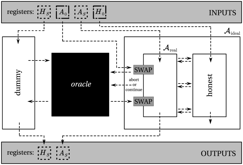
Next we construct the “ideal” execution of the MPQC protocol. The adversary in the “ideal” protocol will internally simulate the “real” protocol with the “real” adversary . Here, the simulated honest quantum nodes will interact with the simulated cheating quantum nodes controlled by the “real” adversary , see Fig. 5. In the “ideal” protocol, the “ideal” adversary and the honest quantum nodes interact with an oracle that perfectly realizes the MPQC protocol and cannot be corrupted. As an input, the oracle requires “dummy” quantum registers of the honest quantum nodes in the simulation , quantum registers of the cheating quantum nodes in the simulation , and a classical flag which indicates whether the oracle should abort the “ideal” protocol or not.
If we denote the input quantum state of all the quantum nodes in the simulation as the entire input into the “ideal” protocol will be . Furthermore, if we denote the general map of the sharing and verification phases as , the quantum state after the sharing and the verification will be denoted as
| (13) |
Before the “ideal” protocol continues to the computation phase, the “ideal” adversary performs an encoding procedure and subsequently applies a gate between the registers and .
-
(a)
Here, if is satisfied, the “ideal” adversary performs an erasure recovery procedure twice, which we denoted as , on the registers of the quantum nodes not in the public set of apparent cheaters and sends register to the oracle.
-
(b)
On the other hand, if is satisfied, the simulated honest quantum nodes replace single-qubit quantum states in their possession with , while the “ideal” adversary sends single-qubit quantum states , as inputs of the simulated cheating quantum nodes, to the oracle. Also, simulated cheating quantum nodes perform arbitrary quantum operation on the shares in their possession.
Therefore, the quantum state after the first interaction with the oracle can be written as
| (14) |
Then, the “ideal” adversary proceeds to the computation phase on the registers and . Meanwhile, the oracle performs the ideal quantum circuit . Therefore, the quantum state after these quantum operations can be written as
| (15) |
Next, depending on the number of apparent cheaters, the “ideal” adversary and the oracle will behave in the following two ways:
-
(a)
If is satisfied, the “ideal” adversary sends the flag “continue” to the oracle and the oracle outputs .
-
(b)
On the other hand, if is satisfied, the “ideal” adversary sends the flag “abort” to the oracle and the oracle outputs the result of the ideal quantum circuit evaluation.
After that, the honest quantum nodes in the simulation output whatever they receive from the oracle as their results. On the other hand, after receiving the output of the oracle the “ideal” adversary does the following:
-
(a)
If is satisfied, the “ideal” adversary performs an encoding procedure twice on the registers , which we denoted as . Finally, the “ideal” adversary applies a gate between the registers and .
-
(b)
If is satisfied, the simulated “real” protocol aborts and the “ideal” adversary outputs the result of the “real” adversary . Finally, simulated cheating quantum nodes perform arbitrary quantum operation on the shares in their possession.
The quantum state after the second interaction with the oracle can be written as
| (16) |
Hereafter, we describe only the case when is satisfied, since it is enough for our purpose. The case when is satisfied can be found in Ref. Lipinska et al. (2020a) as well. To simplify Eq. 16 we employ the identity which holds for any quantum operation and can be written as . By using this identity, as well as Eq. 13, the simplified quantum state after the second interaction with the oracle and in the case when is satisfied can be written as
| (17) |
Note that the simplification in Eq. 17 means that the composition of two gates between the registers and with the ideal quantum circuit performed by the oracle is equivalent to the evaluation of the ideal quantum circuit by the oracle.
Finally, the “ideal” adversary proceeds to the reconstruction phase, in which the simulated honest quantum nodes perform the decoding procedure and the erasure recovery procedure, together denoted as . Simultaneously, the simulated cheating quantum nodes perform arbitrary quantum operation on the shares in their possession and the “ideal” adversary outputs the result of the “real” adversary . Therefore, the output quantum state of the “ideal” protocol can be written as
| (18) |
and, if we employ the identity maps and , Eq. 18 can be further simplified as
| (19) |
VII Summary
To summarize, in this paper we suggested an MPQC protocol built upon a technique of quantum error correction and in particular constructed on the basis of the triply-even CSS QECCs. With the triply-even CSS QECCs at hand, once we decide on the gate, gate, gate, gate, and gate as our universal set of quantum gates, since all the transversal quantum gates can be implemented trivially, the task of the UQC realization in the MPQC protocol reduces to the implementation of the non-transversal gate, which can be easily addressed by the gate teleportation technique. Importantly, this technique requires a logical “plus” state as an ancillary quantum state, which preparation, verification, and confirmation can be accomplished by using the VHSS protocol only. In contrast, the previously suggested MPQC protocol was constructed on the basis of the self-dual CSS QECCs, in which case, the task of the UQC realization cannot be attained without the implementation of the non-transversal gate and the gate teleportation technique comes to aid again. Crucially, the implementation of the non-transversal gate with the gate teleportation technique requires a logical “magic” state as an ancillary quantum state, which preparation, verification, and confirmation can be accomplished only by using a combination of the two sub-protocols: the VHSS protocol and the protocol verifying the “magic” state, the latter of which is implemented by a statistical testing of the randomly selected “magic” states with their subsequent distillation 121212The original version of the protocol verifying the “magic” state employed a non-transversal gate potentially leading to a failure of the entire MPQC protocol.. Therefore, our decision on the triply-even CSS QECCs allows us to avoid execution of the resource-intensive protocol verifying the “magic” state and consequently reduce our demand for the workspace per quantum node from qubits in the previous suggestion to qubits in our case, where is the number of quantum nodes participating in the MPQC protocol and is the security parameter. Besides, since every extra qubit reduces the credibility of physical devices, our suggestion makes the MPQC protocol more accessible for the near-future technology.
Acknowledgements.
The authors would like to thank Suguru Endo, Kaoru Yamamoto, Yuuki Tokunaga, and especially Yasunari Suzuki, for fruitful discussions on the techniques of quantum error correction. The authors also acknowledge Akinori Hosoyamada for insightful comments on the techniques of classical cryptography.References
- Yao (1982) A. C. Yao, “Protocols for secure computations (extended abstract),” in Proceedings of the 23rd Annual Symposium on Foundations of Computer Science, SFCS ’82 (IEEE Computer Society, New York, NY, USA, 1982) pp. 160–164.
- Evans et al. (2018) D. Evans, V. Kolesnikov, and M. Rosulek, “A Pragmatic Introduction to Secure Multi-Party Computation,” Foundations and Trends® in Privacy and Security 2, 70–246 (2018).
- Crépeau et al. (2002) C. Crépeau, D. Gottesman, and A. Smith, “Secure multi-party quantum computation,” in Proceedings of the Thirty-Fourth Annual ACM Symposium on Theory of Computing, STOC ’02 (ACM, New York, NY, USA, 2002) pp. 643–652.
- Smith (2001) A. Smith, “Multi-party quantum computation,” (2001), arXiv:quant-ph/0111030 .
- Ben-Or et al. (2006) M. Ben-Or, C. Crépeau, D. Gottesman, A. Hassidim, and A. Smith, “Secure Multiparty Quantum Computation with (Only) a Strict Honest Majority,” in 47th Annual IEEE Symposium on Foundations of Computer Science, FOCS ’06 (IEEE Computer Society, Berkeley, California, USA, 2006) pp. 249–260.
- Lipinska et al. (2020a) V. Lipinska, J. Ribeiro, and S. Wehner, “Secure multiparty quantum computation with few qubits,” Phys. Rev. A 102, 022405 (2020a).
- Goyal et al. (2022) V. Goyal, C.-D. Liu-Zhang, J. Raizes, and J. Ribeiro, “Asynchronous Multi-Party Quantum Computation,” (2022), Cryptology ePrint Archive, Paper 2022/1583 .
- Dupuis et al. (2010) F. Dupuis, J. B. Nielsen, and L. Salvail, “Secure Two-Party Quantum Evaluation of Unitaries against Specious Adversaries,” in Advances in Cryptology – CRYPTO 2010, Lecture Notes in Computer Science, Vol. 6223, edited by T. Rabin (Springer, Berlin, Heidelberg, 2010) pp. 685–706.
- Dupuis et al. (2012) F. Dupuis, J. B. Nielsen, and L. Salvail, “Actively Secure Two-Party Evaluation of Any Quantum Operation,” in Advances in Cryptology – CRYPTO 2012, Lecture Notes in Computer Science, Vol. 7417, edited by R. Safavi-Naini and R. Canetti (Springer, Berlin, Heidelberg, 2012) pp. 794–811.
- Dulek et al. (2020) Y. Dulek, A. B. Grilo, S. Jeffery, C. Majenz, and C. Schaffner, “Secure Multi-party Quantum Computation with a Dishonest Majority,” in Advances in Cryptology – EUROCRYPT 2020, Lecture Notes in Computer Science, Vol. 12107, edited by A. Canteaut and Y. Ishai (Springer, Cham, 2020) pp. 729–758.
- Alon et al. (2021) B. Alon, H. Chung, K.-M. Chung, M.-Y. Huang, Y. Lee, and Y.-C. Shen, “Round Efficient Secure Multiparty Quantum Computation with Identifiable Abort,” in Advances in Cryptology – CRYPTO 2021, Lecture Notes in Computer Science, Vol. 12825, edited by T. Malkin and C. Peikert (Springer, Cham, 2021) pp. 436–466.
- Bartusek et al. (2021) J. Bartusek, A. Coladangelo, D. Khurana, and F. Ma, “On the Round Complexity of Secure Quantum Computation,” in Advances in Cryptology – CRYPTO 2021, Lecture Notes in Computer Science, Vol. 12825, edited by T. Malkin and C. Peikert (Springer, Cham, 2021) pp. 406–435.
- Huang and Tang (2022) M.-Y. Huang and E.-C. Tang, “From auditable quantum authentication to best-of-both-worlds multiparty quantum computation with public verifiable identifiable abort,” (2022), Cryptology ePrint Archive, Paper 2022/1517 .
- Knill and Laflamme (1997) E. Knill and R. Laflamme, “Theory of quantum error-correcting codes,” Phys. Rev. A 55, 900 (1997).
- Cleve et al. (1999) R. Cleve, D. Gottesman, and H.-K. Lo, “How to share a quantum secret,” Phys. Rev. Lett. 83, 648 (1999).
- Lipinska et al. (2022) V. Lipinska, J. Ribeiro, and S. Wehner, “Secure multiparty quantum computation with few qubits,” (2022), arXiv:2004.10486v2 .
- Lipinska et al. (2020b) V. Lipinska, G. Murta, J. Ribeiro, and S. Wehner, “Verifiable hybrid secret sharing with few qubits,” Phys. Rev. A 101, 032332 (2020b).
- Steane (1996) A. Steane, “Multiple-particle interference and quantum error correction,” Proc. R. Soc. Lond. A. 452, 2551–2577 (1996).
- Calderbank and Shor (1996) A. R. Calderbank and P. W. Shor, “Good quantum error-correcting codes exist,” Phys. Rev. A 54, 1098–1105 (1996).
- Eastin and Knill (2009) B. Eastin and E. Knill, “Restrictions on Transversal Encoded Quantum Gate Sets,” Phys. Rev. Lett. 102, 110502 (2009).
- Gottesman and Chuang (1999) D. Gottesman and I. Chuang, “Demonstrating the viability of universal quantum computation using teleportation and single-qubit operations.” Nature 402, 390–393 (1999).
- Nebe et al. (2001) G. Nebe, E. M. Rains, and N. J. A. Sloane, “The Invariants of the Clifford Groups,” Designs, Codes and Cryptography 24, 99–122 (2001).
- Note (1) In the original version of the MPQC protocol the verification of the “magic” state technique was implemented by the protocol called “verification of the Clifford stabilized states” (VCSS) which contained potential problems coming from the engagement of a non-transversal gate, see Appendix A and Appendix B.
- Betsumiya and Munemasa (2012) K. Betsumiya and A. Munemasa, “On triply even binary codes,” J. London Math. Soc. 86, 1–16 (2012).
- Knill et al. (1996) E. Knill, R. Laflamme, and W. Zurek, “Threshold Accuracy for Quantum Computation,” (1996), arXiv:quant-ph/9610011 .
- Chamberland and Jochym-O’Connor (2017) C. Chamberland and T. Jochym-O’Connor, “Error suppression via complementary gauge choices in Reed-Muller codes,” Quantum Science and Technology 2, 035008 (2017).
- Note (2) Namely, is equal to the number of times the VHSS protocol is invoked during the execution of the MPQC protocol.
- Canetti et al. (1999) R. Canetti, J. Garay, G. Itkis, D. Micciancio, M. Naor, and B. Pinkas, “Multicast security: a taxonomy and some efficient constructions,” in IEEE INFOCOM ’99. Conference on Computer Communications. Proceedings. Eighteenth Annual Joint Conference of the IEEE Computer and Communications Societies. The Future is Now (Cat. No.99CH36320), Vol. 2 (IEEE, New York, NY, USA, 1999) pp. 708–716.
- Lamport et al. (1982) L. Lamport, R. Shostak, and M. Pease, “The Byzantine Generals Problem,” ACM Trans. Program. Lang. Syst. 4, 382–401 (1982).
- Pease et al. (1980) M. Pease, R. Shostak, and L. Lamport, “Reaching Agreement in the Presence of Faults,” J. ACM 27, 228–234 (1980).
- Ben-Or et al. (1988) M. Ben-Or, S. Goldwasser, and A. Wigderson, “Completeness theorems for non-cryptographic fault-tolerant distributed computation,” in Proceedings of the 20th Annual ACM Symposium on Theory of Computing, STOC ’88 (Association for Computing Machinery, New York, NY, USA, 1988) pp. 1–10.
- Chaum et al. (1988) D. Chaum, C. Crépeau, and I. Damgard, “Multiparty unconditionally secure protocols,” in Proceedings of the 20th Annual ACM Symposium on Theory of Computing, STOC ’88 (Association for Computing Machinery, New York, NY, USA, 1988) pp. 11–19.
- Note (3) We note that aforementioned constraints on the feasibility of the classical authenticated broadcast channel and the public source of randomness do not cause any additional problems since we assume that only quantum nodes are corrupted by the adversary, see Sec. III.2.
- Canetti (2004) R. Canetti, “Universally composable signature, certification, and authentication,” in Proceedings. 17th IEEE Computer Security Foundations Workshop, 2004. (IEEE, Pacific Grove, CA, USA, 2004) pp. 219–233.
- Barnum et al. (2002) H. Barnum, C. Crépeau, D. Gottesman, A. Smith, and A. Tapp, “Authentication of quantum messages,” in The 43rd Annual IEEE Symposium on Foundations of Computer Science, 2002. Proceedings. (IEEE, Vancouver, BC, Canada, 2002) pp. 449–458.
- Note (4) Non-adaptive is the adversary that chooses quantum nodes to corrupt before the MPQC protocol begins and remains with that choice.
- Note (5) Active is the adversary that is able to perform arbitrary quantum operations on the shares in the possession of the corrupted quantum nodes.
- Nielsen and Chuang (2011) M. A. Nielsen and I. L. Chuang, Quantum Computation and Quantum Information: 10th Anniversary Edition, 10th ed. (Cambridge University Press, New York, NY, USA, 2011).
- Preskill (1999) J. Preskill, Lecture notes for Physics 219: Quantum Computation, Lecture Notes (California Institute of Technology, 1999).
- Steane (1997) A. M. Steane, “Active Stabilization, Quantum Computation, and Quantum State Synthesis,” Phys. Rev. Lett. 78, 2252 (1997).
- Rengaswamy et al. (2020) N. Rengaswamy, R. Calderbank, M. Newman, and H. D. Pfister, “On Optimality of CSS Codes for Transversal ,” IEEE Journal on Selected Areas in Information Theory 1, 499–514 (2020).
- Bravyi and Haah (2012) S. Bravyi and J. Haah, “Magic-state distillation with low overhead,” Phys. Rev. A 86, 052329 (2012).
- Paetznick (2014) A. Paetznick, “Resource optimization for fault-tolerant quantum computing,” (2014), arXiv:1410.5124 .
- Nezami and Haah (2022) S. Nezami and J. Haah, “Classification of small triorthogonal codes,” Phys. Rev. A 106, 012437 (2022).
- Note (6) This statement is indeed consistent with the claim that the condition is satisfied for all the even weight rows of the triply-even binary matrix .
- Note (7) This is different from the VHSS protocol employed to check whether the quantum node is honest or not by simply verifying the encoding of the input .
- Gottesman (2009) D. Gottesman, “An Introduction to Quantum Error Correction and Fault-Tolerant Quantum Computation,” (2009), arXiv:0904.2557 .
- Note (8) For the details of the protocol called “verification of the Clifford stabilizer states” (VCSS) which was employed in the original version of the MPQC protocol for the verification of the ancillary logical “magic” state see Appendix A and Appendix B.
- Beaver (1992) D. Beaver, “Foundations of Secure Interactive Computing,” in Advances in Cryptology – CRYPTO ’91, edited by J. Feigenbaum (Springer Berlin Heidelberg, Berlin, Heidelberg, 1992) pp. 377–391.
- Micali and Rogaway (1992) S. Micali and P. Rogaway, “Secure Computation,” in Advances in Cryptology – CRYPTO ’91, edited by J. Feigenbaum (Springer Berlin Heidelberg, Berlin, Heidelberg, 1992) pp. 392–404.
- Canetti (2001) R. Canetti, “Universally Composable Security: A New Paradigm for Cryptographic Protocols,” in Proceedings 42nd IEEE Symposium on Foundations of Computer Science (2001) pp. 136–145.
- Unruh (2010) D. Unruh, “Universally Composable Quantum Multi-party Computation,” in Advances in Cryptology – EUROCRYPT 2010, edited by H. Gilbert (Springer Berlin Heidelberg, Berlin, Heidelberg, 2010) pp. 486–505.
- Note (9) In the Ref. Lipinska et al. (2022) it was shown that the security proofs of the original version of the MPQC protocol in Ref. Lipinska et al. (2020a) and the reconsidered version of the MPQC protocol in Ref. Lipinska et al. (2022) are identical.
- Gottesman (1998) D. Gottesman, “Theory of fault-tolerant quantum computation,” Phys. Rev. A 57, 127 (1998).
- Note (10) The same can be said also for the protocol called “verification of the Clifford stabilized states” (VCSS), see Appendix A and Appendix B.
- Cramer et al. (2015) R. Cramer, I. B. Damgard, and J. B. Nielsen, Secure Multiparty Computation and Secret Sharing, 1st ed. (Cambridge University Press, New York, NY, USA, 2015).
- Note (11) If we suppose that the VHSS protocol involved in the construction of the MPQC protocol has no any probability of error, one will actually achieve .
- Note (12) The original version of the protocol verifying the “magic” state employed a non-transversal gate potentially leading to a failure of the entire MPQC protocol.
- Note (13) For the self-dual CSS QECCs gate is transversal.
- Hölting (2020) J. G. Hölting, On secret sharing-based classical and quantum multi-party computation, Master’s thesis, Universiteit Utrecht (2020).
- Bravyi and Kitaev (2005) S. Bravyi and A. Kitaev, “Universal quantum computation with ideal Clifford gates and noisy ancillas,” Phys. Rev. A 71, 022316 (2005).
Appendix A Summary of the VCSS protocol
Here we briefly describe the VCSS protocol which is necessary for the verification of the ancillary logical “magic” state , i.e., whether it is certainly a logical “magic” state or not, in case of the original version of the MPQC protocol based on self-dual CSS QECCs Lipinska et al. (2020a). The idea of the VCSS protocol construction is inspired by the procedure of the stabilizer measurement in the technique of quantum error correction. To begin with, consider gate, and the “magic” state which is a eigenstate of the gate (see Sec. B for the criticism towards this claim). Then the equation holds, where gate is applied between the single-qubit quantum state acting as the control quantum state and the ancillary “magic” state acting as the target quantum state. This insight suggests on how to implement the verification of the . If the target quantum state was , then after applying gate one will always measure the control quantum state in the . On the other hand, if the target quantum state was not and one measures the control quantum state in the , then one has projected the target quantum state onto the .
The above procedure can be adapted to confirm that the quantum state in the possession of the quantum nodes is for sure an anticipated ancillary logical “magic” state. First, by using the VHSS protocol, quantum nodes jointly verify and confirm the logical quantum state , see Sec. IV.1. Second, by using the VHSS protocol one more time quantum nodes jointly verify that the quantum state in their possession is for sure a valid logical quantum state encoded by a self-dual CSS QECC, see Sec. IV.1. Next, to obtain the logical quantum state quantum nodes transversally apply gate 131313For the self-dual CSS QECCs gate is transversal. to the logical quantum state , and subsequently apply gate to their shares, taking shares of the logical quantum state as the control shares and shares of the logical quantum state as the target shares. Then, quantum nodes one more time transversally apply gate to the control shares and logically measure them in the standard basis. Finally, quantum nodes decode the result of the logical measurement twice and publicly check whether their twice decoded result corresponds to . In parallel, quantum nodes update a public set of apparent cheaters . Note that the above procedure works if and only if the gate is transversal for a self-dual CSS QECC (see Sec. B for the criticism towards this claim).
Execution of the VCSS protocol requires a workspace of qubits per quantum node. First, verification of the logical quantum state requires a workspace of qubits per quantum node. Second, after the verification of the logical quantum state , each quantum node requires a workspace of qubits for holding this logical quantum state and in addition, uses extra workspace of qubits for verification of the logical quantum state . Thus in total, each quantum node requires a workspace of qubits for the execution of the VCSS protocol. The communication complexity of the VCSS protocol is the same as of the VHSS protocol, i.e., qubits per quantum node.
Appendix B Criticism towards the VCSS protocol
Here we describe two problems underlying the implementation of the VCSS protocol suggested in Ref. Lipinska et al. (2020a). Authors of the Ref. Lipinska et al. (2020a) claim that the “magic” state is a eigenstate of the gate while in reality, it is a eigenstate, see Ref. Hölting (2020) for calculations. This fact alone may cause some problems when applying gate during the execution of the VCSS protocol, but the issue can be easily fixed by applying gate instead, since is indeed a eigenstate of the gate. Furthermore, authors of the Ref. Lipinska et al. (2020a) claim that the VCSS protocol works as long as the gate can be implemented transversally. However, the gate is not transversal for the self-dual CSS QECCs. First of all, it is known to be impossible to implement an entire universal set of quantum gates transversally for any QECC Eastin and Knill (2009). Therefore, the gate needs to be a Clifford gate. Actually, gate can be easily decomposed as , which implies that the gate is a Clifford gate. But the gate is obviously not a Clifford gate and we attain a contradiction.
Appendix C Outline of the “magic” state verification protocol
Here we briefly describe the protocol necessary for the verification of the ancillary logical “magic” state , i.e., whether it is certainly logical “magic” state or not, in case of the reconsidered version of the MPQC protocol suggested in Ref. Lipinska et al. (2022). The protocol we describe here circumvents the questionable applicability of the VCSS protocol suggested in the original version of the MPQC protocol in Ref. Lipinska et al. (2020a). The ambiguity in the VCSS protocol comes from the engagement of the gate, which is non-transversal in case of the self-dual CSS QECCs.
The protocol verifying the ancillary logical “magic” state relies on a statistical testing of the randomly selected “magic” states , with the subsequent distillation of the logical “magic” states via the distributed version of the -to- magic state distillation protocol Bravyi and Kitaev (2005). This approach increases the workspace required for the implementation of the MPQC protocol from qubits per quantum node in the original suggestion Lipinska et al. (2020a) to qubits per quantum node in the reconsidered suggestion Lipinska et al. (2022), where is the number of the quantum nodes and is the security parameter. Fortunately, the security proof does not change between the two versions of the MPQC protocol.
In short, the verification of the “magic” state technique is performed as follows Lipinska et al. (2022). First of all, quantum nodes jointly prepare copies of the verified by the VHSS protocol logical “magic” state , see Sec. IV.1. Next, by using the public source of randomness, quantum nodes jointly select out of copies, and to perform the statistical testing of the randomly selected “magic” states, randomly ascribe some quantum node to each selected copy. After that, each quantum node collects all the single-qubit quantum states corresponding to the copy ascribed to him and by decoding it twice reconstructs a “magic” state , see Sec. IV.1. Then, each quantum node measures the reconstructed “magic” state in the basis and if all the measurement results correspond to the “magic” state then the quantum nodes can be sure that the remaining copies of the logical quantum state in their possession is for sure an anticipated logical “magic” states with high probability. In parallel, quantum nodes update a public set of apparent cheaters . After that, the dephasing procedure is performed, where by using the public source of randomness, quantum nodes randomly apply the gate to each of the remaining copies of the logical quantum state in such a way bringing them into the form diagonal in the basis, and subsequently randomly permute these copies of the logical quantum state . Finally, quantum nodes jointly perform the distillation of the logical “magic” state by using the distributed version of the -to- magic state distillation protocol Bravyi and Kitaev (2005) which can be implemented by combining the transversal quantum gates with the transversally implemented logical measurements in case of the self-dual CSS QECCs.
Execution of the above protocol requires a workspace of qubits per quantum node, since during the verification of the “magic” state quantum nodes should jointly prepare copies of the verified by the VHSS protocol logical “magic” state . The communication complexity of the above protocol is qubits per quantum node since in addition to the executions of the VHSS protocol the verification of the “magic” state technique requires a collection of the randomly selected copies of the logical “magic” state .
Appendix D Definitions of the quantum gates
We define single-qubit quantum gates used throughout the manuscript, i.e., gate, gate, gate, gate, gate, and gate in a matrix form as follows:
As well, we define two-qubit quantum gates used throughout the manuscript, i.e., gate, and gate as follows:
Appendix E Teleportation of the gate

Here we explicate the detailed calculations behind the teleportation of the gate. For the sake of simplicity, let us consider the quantum circuit which takes single-qubit quantum state (alternatively ) and ancillary quantum state as an input, see Fig. 6. The calculations before the measurement in the Fourier basis are straightforward and the two-qubit result can be written in the matrix form as
| (22) |
Next, to implement the measurement in the Fourier basis, let us define the measurement operators as and for the two measurement outcomes which, by using the result in Eq. 22, can be written as follows:
| (23) | |||
| (24) |
and if we write Eqs. 23 and 24 explicitly, the result will be:
| (25) | |||
| (26) |
As one can observe, we obtain an anticipated result in case of Eq. 26, i.e., the gate is definitely applied to the single-qubit input quantum state (alternatively ). On the other hand, in case of Eq. 25 we do not obtain an anticipated result and an additional application of the gate is required. The result of the gate application can be explicitly written as
| (27) |
and one can observe that we indeed obtain and anticipated result where the gate is applied to the single-qubit input quantum state (alternatively ).