This paper was converted on www.awesomepapers.org from LaTeX by an anonymous user.
Want to know more? Visit the Converter page.

Secure Transmission by Leveraging Multiple Intelligent Reflecting Surfaces in MISO Systems

Jian Li,  Lan Zhang,  Kaiping Xue,  Yongdong Zhang,  and Yuguang Fang
Abstract

Due to the broadcast nature of wireless communications, physical layer security has always been a fundamental but challenging problem. Recent advance of Intelligent Reflecting Surface (IRS) introduces a new dimension for secure communications by reconfiguring the transmission environments. In this paper, we devise a secure transmission scheme for multi-user MISO systems by leveraging multiple collaborative IRSs. Specifically, to guarantee the worst-case achievable secrecy rate among multiple legitimate users, we formulate a max-min problem that can be solved by an alternative optimization method to decouple it into multiple sub-problems. Based on semidefinite relaxation and successive convex approximation, each sub-problem can be further converted into convex problem and easily solved. Extensive experimental results demonstrate that our proposed scheme can adapt to complex scenarios for multiple users and achieve significant gain in terms of achievable secrecy rate. The gap between the secrecy rate from our proposed scheme and that from the traditional sum-rate maximization and our results show that the secrecy rate obtained from our scheme converges to that achieved from the traditional sum-rate maximization when increasing the number of elements on IRSs.

Index Terms:
Physical layer security, intelligent reflecting surface, secrecy rate.

I Introduction

Due to the broadcast nature of wireless signals, it is vulnerable for user’s confidential messages in wireless communications. To safeguard communication security, physical layer security, which can be traced back to 1970’s Wyner’s seminal work [1, 2, 3], has been regarded as a key complement to higher-layer encryption techniques [4, 5]. In traditional communication systems, beamforming and Artificial Noise (AN) are considered as two effective approaches to defending against wiretapping channel and achieving secure communication [6, 7, 8, 9]. By exploiting multiple antennas and shaped beams, beamforming technology can be implemented to direct the signal towards the legitimate user and thus reduce the signal leakage. In addition to beamforming, AN technology can create significant interference and lower the SINR at eavesdroppers by properly designing AN signals. Thus, the achievable secrecy rate, which is a widely used criterion to capture the difference between mutual information of “Alice-Bob” intended channel and “Alice-Eve” eavesdropping channel and measure the security level, can be effectively improved especially when the channel state of transmitter-user and transmitter-eavesdropper are highly correlative during the transmission. Nevertheless, due to the complex environment of wireless communications, the proposed approaches do not always work as expected.

As a promising technology to achieve smart radio environment/intelligent radio environment in next generation cellular systems [10, 11], Intelligent Reflecting Surfaces (IRSs) can provide reconfigurable signal propagation environments to support cost-effective and power-efficient wireless communication services. Specifically, IRS is a metasurface composed of a large number of passive reflecting elements, which consumes much lower energy compared with traditional active relays/transceivers [12, 13]. By adaptively adjusting the reflection amplitude and/or phase shift of each element, the strength and direction of the incident electromagnetic wave becomes highly controllable. Thus, IRS is regarded as a novel solution to achieving configurable wireless transmission environment/intelligent radio environment/wireless 2.0 with low hardware/energy cost, and has been applied in various wireless applications such as coverage extension, interference cancellation, and energy efficiency enhancement [12, 10, 14]. Particularly, Zhang et al. [15, 14] articulate how to augment transmission environments with cheap reflectors without damaging aesthetic nature of users’ surrounding to boost transmission performance and present high layer implementation consideration. Due to the aforementioned advantages, the IRS-assisted communication systems have great potential to enhance physical layer security. By jointly optimizing operations on transmitter and passive reflecting elements of IRS, the transmitter-user channel state can be reconfigured to lower the signal leakage to eavesdroppers. Intuitively, users geographically close to the IRS are more likely beneficial from IRS by receiving the tuned signal, whose achievable secrecy rate can be significantly improved.

Recently, some efforts have been made to study IRS-assisted systems for physical layer security. Cui et al. [16] investigated an IRS-aided secure wireless communication systems where a simple scenario with one eavesdropper is investigated to show the effectiveness of IRS. To explore the effectiveness of traditional approach in IRS-assisted scenarios, Guan et al. [5] further considered AN in an IRS-assisted system, whose performance was verified with the significant gain on secrecy rate. To improve the algorithm efficiency, Yu et al. [17] proposed an efficient algorithm adopting block coordinate descent and minorization maximization method for faster convergence especially for large-scale IRS. Dong et al. [18] also adopted a similar efficient design for Mutiple-Input Mutiple-Output (MIMO) systems. Lyu et al. [19] considered a potential IRS threat called IRS jamming attack, which can leverage signals from a transmitter by controlling reflected signals to diminish the signal-to-interference-plus-noise ratio at the user. Since the IRS jammer operates in a passive way, it can be even harder to defend. Xu et al. [20] studied resource allocation design in multi-user scenarios and also considered AN at transmitter. However, the aforementioned efforts only focus on the proof-of-concept study by implementing a single IRS. Thus, the security gain from leveraging multiple collabortive IRSs has not been explored yet, and it is also paramount to jointly optimize wireless transmission environments and allocate resources for legitimate users in multiple IRSs-assisted systems.

To enhance transmission the security from users, in this paper, we study secure transmission schemes for multi-user Mutiple-Input Singe-Output (MISO) systems assisted by multiple collaborative IRSs. The main contributions of this paper are summarized as follows.

  • To deal with the threat from potential eavesdroppers, we propose a secure communication scheme in multiple IRSs-assisted systems. Considering the security requirement for each legitimate user, we formulate a max-min problem to maximize the lower bound of the secrecy rate to optimize the worst performance of multiple users in case eavesdroppers “steal” useful information from a certain user.

  • To solve the formulated max-min problem, we adopt an alternating algorithm to decouple it into multiple sub-problems. In each iteration, we apply Semi-Definite Relaxation (SDR) and Successive Convex Approximation (SCA) method to solve a convex optimization problem.

  • To verify the effectiveness of the proposed scheme, extensive numerical evaluations are conducted. Compared with the traditional IRS scheme with beamforming, the results show that the proposed scheme can achieve significant improvement, and the additional AN can improve achievable secrecy rate especially in multi-user scenarios. Moreover, we compare our scheme with the traditional sum-rate problem to show the gap of security performance. With the increase in the number of elements on IRSs, we show that the performance from our scheme converges to that from the sum-rate maximization in terms of sum of secrecy rate.

Symbol Notation: Boldface lowercase and uppercase letters denote vectors and matrices, respectively. For a vector 𝐚\mathbf{a}, 𝐚||\mathbf{a}|| denotes the Euclidean norm. For matrix 𝐀\mathbf{A}, the conjugate transpose, rank and trace of 𝐀\mathbf{A} are denoted as 𝐀H\mathbf{A}^{H}, Rank(𝐀){\rm Rank}(\mathbf{A}) and Tr(𝐀){\rm Tr}(\mathbf{A}), respectively. For a complex number cc, |c||c| denotes the modulus. angle(c)angle(c) denotes the phase of the complex value cc. The set of nn-by-mm real matrices, complex matrices and complex Hermitian matrices are denoted as n×m\mathbb{R}^{n\times m}, n×m\mathbb{C}^{n\times m} and n×m\mathbb{H}^{n\times m}, respectively. 𝐀0\mathbf{A}\succeq 0 means 𝐀\mathbf{A} is a positive semidefinite matrix, and 𝒩(μ,)\mathcal{N}(\mu,\sum) denotes the Gaussian distribution with mean μ\mu and covariance matrix \sum.

II System Model

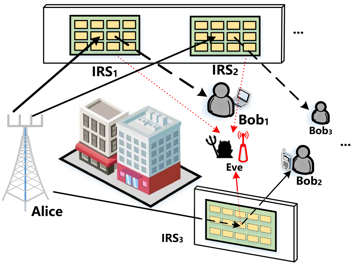
We consider a wireless communication system as shown in Fig. 1, a base station equipped with MM antennas intends to transmit secure messages to II legitimate users equipped with single antenna. Moreover, KK IRSs have been deployed in advance to assist wireless communications, and each IRS has NN reflecting elements.

Adversary Model: With respect to the transmitted secure messages, one eavesdropper (Eve) wants to wiretap/intercept transmitted signals, and further crack the secure messages to steal users’ private information or hack users’ equipments. To eliminate the potential threat from the eavesdropper and protect the security of legitimate users, the base station and IRSs need to cooperatively transmit signals to increase received signal power at legitimate users while mitigating the signal leakage at the eavesdropper. In this paper, we attempt to adjust the transmission strategy both at base station and on IRSs to enhance the security level.

Channel Model: There are two parts of a channel experienced from base station to user/Eve, i.e., direct (transmitter-user/Eve) channel and reflecting (transmitter-IRS-user/Eve) channel. The composite reflecting channel is modeled as a combination of three components, i.e., the base station to IRS link, IRS’s reflection with phase shift and IRS to user/Eve link. The equivalent channels from the base station to the kk-th IRS, the ii-th user and Eve are denoted by 𝑮kHN×M\boldsymbol{G}^{H}_{k}\in\mathbb{C}^{N\times M}, 𝒉iH1×M\boldsymbol{h}_{i}^{H}\in\mathbb{C}^{1\times M}, 𝒉eH1×M\boldsymbol{h}^{H}_{e}\in\mathbb{C}^{1\times M}, respectively. The equivalent channels from the kk-th IRS to the ii-th user and Eve are denoted by 𝒈i,kH1×N\boldsymbol{g}^{H}_{i,k}\in\mathbb{C}^{1\times N}, 𝒈eH1×N\boldsymbol{g}^{H}_{e}\in\mathbb{C}^{1\times N}, respectively. Since IRS is a passive reflecting device, we consider a Time Division Duplexing (TDD) protocol for uplink and downlink transmissions and quasi-static flat-fading model (constant within the transmission frame) is adopted for all channels. As discussed in [12, 5, 21], by applying various channel acquisition methods, we can acquire all channel information, and hence here for the current study, we also assume that the Channel State Information (CSI) of all channels are perfectly known. Linear transmit precoding is considered at the base station similar to [13], and each user served by the base station is assigned with one dedicated beamforming vector. To further enhance the physical layer security, additional AN is also adopted. Thus, the signal transmitted from the base station to the ii-th user can be described as:

𝒙i=𝝎isi+𝒛i,i=1,U,\boldsymbol{x}_{i}=\boldsymbol{\omega}_{i}s_{i}+\boldsymbol{z}_{i},i=1,...U, (1)

where 𝝎iM×1\boldsymbol{\omega}_{i}\in\mathbb{C}^{M\times 1} is the beamforming vector for the ii-th user, sis_{i} is the corresponding transmitted data, and 𝒛iM×1\boldsymbol{z}_{i}\in\mathbb{C}^{M\times 1} is an AN vector.

Since multiple IRSs have been deployed in the system, each legitimate user can be served by a selected IRS to receive tuned signal, which is effective especially when there exists an obstacle and no Light-of-Sight (LoS) channel between the base station and a user. Let αi,k{0,1}\alpha_{i,k}\in\{0,1\} denote the IRS selection for the ii-th user, i.e., the ii-th user can receive reflecting signal through the kk-th IRS if αi,k=1\alpha_{i,k}=1. Meanwhile, let 𝚯k=diag(Ak,1ejθk,1,,Ak,Nejθk,N)N×N\boldsymbol{\Theta}_{k}={\rm diag}(A_{k,1}e^{j\theta_{k,1}},...,A_{k,N}e^{j\theta_{k,N}})\in\mathbb{C}^{N\times N} denote the diagonal phase-shifting matrix of the kk-th IRS, while Ak,n[0,1]A_{k,n}\in[0,1] and θk,n[0,2π)\theta_{k,n}\in[0,2\pi) denote the amplitude reflection coefficient and the phase shift of the nn-th element on the kk-th IRS. In practice, each element of an IRS is usually designed to maximize the signal reflection [13]. Thus, we set Ak,n=1A_{k,n}=1 in this paper. In this case, for the ii-th user, the received signal from base station and IRSs can be represented by:

𝒚i=\displaystyle\boldsymbol{y}_{i}= (k=1Kαi,k𝒈i,kH𝚯k𝑮kH+𝒉iH)(𝝎isi+𝒛i)+\displaystyle(\sum\limits_{k=1}^{K}\alpha_{i,k}\boldsymbol{g}_{i,k}^{H}\boldsymbol{\Theta}_{k}\boldsymbol{G}^{H}_{k}+\boldsymbol{h}_{i}^{H})(\boldsymbol{\omega}_{i}s_{i}+\boldsymbol{z}_{i})+
ji(k=1Kαj,k𝒈i,kH𝚯k𝑮kH+𝒉iH)(𝝎jsi+𝒛j)+n0,\displaystyle\sum\limits_{j\neq i}(\sum\limits_{k=1}^{K}\alpha_{j,k}\boldsymbol{g}_{i,k}^{H}\boldsymbol{\Theta}_{k}\boldsymbol{G}^{H}_{k}+\boldsymbol{h}_{i}^{H})(\boldsymbol{\omega}_{j}s_{i}+\boldsymbol{z}_{j})+n_{0}, (2)

where n0𝒞𝒩(0,σ2)n_{0}\in\mathcal{CN}(0,\sigma^{2}) is the complex Additive White Gaussian Noise (AWGN). For an eavesdropper, the received signal can be represented by:

𝒚ie=\displaystyle\boldsymbol{y}^{e}_{i}= (k=1Kαi,k𝒈e,kH𝚯k𝑮kH+𝒉eH)(𝝎isi+𝒛i)\displaystyle(\sum\limits_{k=1}^{K}\alpha_{i,k}\boldsymbol{g}_{e,k}^{H}\boldsymbol{\Theta}_{k}\boldsymbol{G}^{H}_{k}+\boldsymbol{h}^{H}_{e})(\boldsymbol{\omega}_{i}s_{i}+\boldsymbol{z}_{i})
ji(k=1Kαj,k𝒈e,kH𝚯k𝑮kH+𝒉eH)(𝝎jsi+𝒛j)+n0.\displaystyle\sum\limits_{j\neq i}(\sum\limits_{k=1}^{K}\alpha_{j,k}\boldsymbol{g}_{e,k}^{H}\boldsymbol{\Theta}_{k}\boldsymbol{G}^{H}_{k}+\boldsymbol{h}_{e}^{H})(\boldsymbol{\omega}_{j}s_{i}+\boldsymbol{z}_{j})+n_{0}. (3)

For notational simplicity, let 𝑫^ij=k=1Kαj,k𝒈i,kH𝚯k𝑮kH+𝒉iH1×M\boldsymbol{\hat{D}}_{ij}=\sum\limits_{k=1}^{K}\alpha_{j,k}\boldsymbol{g}^{H}_{i,k}\boldsymbol{\Theta}_{k}\boldsymbol{G}^{H}_{k}+\boldsymbol{h}^{H}_{i}\in\mathbb{C}^{1\times M}, 𝑫e,i=k=1Kαi,k𝒈e,kH𝚯k𝑮kH+𝒉eH1×M\boldsymbol{D}_{e,i}=\sum\limits_{k=1}^{K}\alpha_{i,k}\boldsymbol{g}^{H}_{e,k}\boldsymbol{\Theta}_{k}\boldsymbol{G}^{H}_{k}+\boldsymbol{h}^{H}_{e}\in\mathbb{C}^{1\times M}. Accordingly, the Signal-to-Noise Ratio (SINR) of received signal at the ii-th user can be calculated by:

SINRi=|(k=1Kαi,k𝒈i,kH𝚯k𝑮kH+𝒉iH)𝝎i|2ji|(𝑫^ij𝝎j|2+j𝒰|𝑫^ij𝒛j|2+N0,SINR_{i}=\frac{|(\sum\limits_{k=1}^{K}\alpha_{i,k}\boldsymbol{g}_{i,k}^{H}\boldsymbol{\Theta}_{k}\boldsymbol{G}^{H}_{k}+\boldsymbol{h}_{i}^{H})\boldsymbol{\omega}_{i}|^{2}}{\sum\limits_{j\neq i}|(\boldsymbol{\hat{D}}_{ij}\boldsymbol{\omega}_{j}|^{2}+\sum\limits_{j\in\mathcal{U}}|\boldsymbol{\hat{D}}_{ij}\boldsymbol{z}_{j}|^{2}+N_{0}}, (4)

where N0N_{0} is the power of AWGN. Similarly, the SINR of the ii-th user’s signal at the eavesdropper can be calculated by:

SINRie=|(k=1Kαi,k𝒈e,kH𝚯k𝑮kH+𝒉eH)𝝎i|2ji|𝑫e,j𝝎j|2+j𝒰|𝑫e,j𝒛j|2+N0.SINR^{e}_{i}=\frac{|(\sum\limits_{k=1}^{K}\alpha_{i,k}\boldsymbol{g}_{e,k}^{H}\boldsymbol{\Theta}_{k}\boldsymbol{G}^{H}_{k}+\boldsymbol{h}_{e}^{H})\boldsymbol{\omega}_{i}|^{2}}{\sum\limits_{j\neq i}|\boldsymbol{D}_{e,j}\boldsymbol{\omega}_{j}|^{2}+\sum\limits_{j\in\mathcal{U}}|\boldsymbol{D}_{e,j}\boldsymbol{z}_{j}|^{2}+N_{0}}. (5)
Refer to caption
Figure 1: System model of IRSs-assisted secure transmissions.

III Problem Formulation and Solution

Considering the security requirement for each legitimate user in the system, we want to guarantee the worst performance of all legitimate users in case an eavesdropper might wiretap/intercept too much useful information from a certain user. Thus, in this paper, we aim to maximize the minimum achievable secrecy rate of legitimate users in the system. By jointly configuring the beamforming matrix 𝝎¯=[𝝎1,𝝎2,𝝎I]\boldsymbol{\bar{\omega}}=[\boldsymbol{\omega}_{1},\boldsymbol{\omega}_{2}...,\boldsymbol{\omega}_{I}] and AN matrix 𝒛¯=[𝒛1,𝒛2,𝒛I]\boldsymbol{\bar{z}}=[\boldsymbol{z}_{1},\boldsymbol{z}_{2}...,\boldsymbol{z}_{I}] at the base station, phase shift matrix 𝚯¯=[𝚯1,𝚯2,,𝚯K]\boldsymbol{\bar{\Theta}}=[\boldsymbol{\Theta}_{1},\boldsymbol{\Theta}_{2},...,\boldsymbol{\Theta}_{K}] at IRSs and surface selection matrix 𝜶¯=[𝜶1,1𝜶1,K𝜶I,1𝜶I,K]\boldsymbol{\bar{\alpha}}=\begin{bmatrix}\boldsymbol{\alpha}_{1,1}&...&\boldsymbol{\alpha}_{1,K}\\ ...&...&...\\ \boldsymbol{\alpha}_{I,1}&...&\boldsymbol{\alpha}_{I,K}\end{bmatrix} between users and IRSs, the optimization problem can be formulated as:

Problem  1:max𝝎¯,𝒛¯,𝚯¯,𝜶¯mini[RiuRie]+\textbf{Problem ~1}:~~~\max\limits_{\boldsymbol{\bar{\omega}},\boldsymbol{\bar{z}},\boldsymbol{\bar{\Theta}},\boldsymbol{\bar{\alpha}}}~\min\limits_{i}~~~[R_{i}^{u}-R_{i}^{e}]^{+} (6)
s.t.\displaystyle s.t.~~~ 𝝎i2+𝒛i2Pmax,i𝒰,\displaystyle||\boldsymbol{\omega}_{i}||^{2}+||\boldsymbol{z}_{i}||^{2}\leq P_{max},~\forall i\in\mathcal{U}, (C1)
0θk,n2π,k[1,K],n[1,N],\displaystyle 0\leq\theta_{k,n}\leq 2\pi,~k\in[1,K],\forall n\in[1,N], (C2)
kαi,k=1,αi,k{0,1},i𝒰,\displaystyle\sum\limits_{k}\alpha_{i,k}=1,~\alpha_{i,k}\in\{0,1\},~\forall i\in\mathcal{U}, (C3)

where (C1) represents the transmission power constraint, (C2) implies the unit modulus for each element, i.e., |ejθk,n|=1|e^{j\theta_{k,n}}|=1, and (C3) indicates that each user should be served by one IRS in the system. Considering the SINR expression in (4), (5) and applying the Shannon capacity theorem, the achievable secrecy rate (bits/s/Hz) in (6) can be calculated by:

RiuRie=log2(1+|(k=1Kαi,k𝒈i,kH𝚯kGkH+𝒉iH)𝝎i|2ji|(𝑫^ij𝝎j|2+j𝒰|𝑫^ij𝒛j|2+N0)\displaystyle R^{u}_{i}-R^{e}_{i}=\log_{2}(1+\frac{|(\sum\limits_{k=1}^{K}\alpha_{i,k}\boldsymbol{g}^{H}_{i,k}\boldsymbol{\Theta}_{k}G^{H}_{k}+\boldsymbol{h}^{H}_{i})\boldsymbol{\omega}_{i}|^{2}}{\sum\limits_{j\neq i}|(\boldsymbol{\hat{D}}_{ij}\boldsymbol{\omega}_{j}|^{2}+\sum\limits_{j\in\mathcal{U}}|\boldsymbol{\hat{D}}_{ij}\boldsymbol{z}_{j}|^{2}+N_{0}})
log2(1+|(k=1Kαi,k𝒈e,kH𝚯kGkH+𝒉eH)𝝎i|2ji|(𝑫e,j𝝎j|2+j𝒰|𝑫e,j𝒛j|2+N0).\displaystyle-\log_{2}(1+\frac{|(\sum\limits_{k=1}^{K}\alpha_{i,k}\boldsymbol{g}^{H}_{e,k}\boldsymbol{\Theta}_{k}G^{H}_{k}+\boldsymbol{h}^{H}_{e})\boldsymbol{\omega}_{i}|^{2}}{\sum\limits_{j\neq i}|(\boldsymbol{D}_{e,j}\boldsymbol{\omega}_{j}|^{2}+\sum\limits_{j\in\mathcal{U}}|\boldsymbol{D}_{e,j}\boldsymbol{z}_{j}|^{2}+N_{0}}). (7)

It is intuitive that variables 𝝎¯\boldsymbol{\bar{\omega}}, 𝒛¯\boldsymbol{\bar{z}}, 𝚯¯\boldsymbol{\bar{\Theta}} and 𝜶¯\boldsymbol{\bar{\alpha}} in Problem 1 are coupled, which makes Problem 1 hard to solve. However, if only one variable is considered, the original problem becomes solvable. Inspired by the alternating optimization approaches in [5, 17, 18, 19, 20, 13, 22], we adopt Block Coordinate Descent (BCD) method to decouple variables and obtain the sub-optimal solution efficiently. To optimize a multi-variable objective in BCD method, we optimize the objective in terms of one of the coordinate blocks while the other blocks are fixed at each iteration. Thus, Problem 1 is divided into three sub-problems and each sub-problem is solved iteratively as descried in Algorithm 1. For each sub-problem, we utilize SDR and SCA to convert the original problem into a convex problem. The detailed solving process of each sub-problem is descried in the following sub-sections.

Input: Number of elements NN, number of antennas MM, number of surfaces KK;
Output: Beamforming vector 𝝎¯\boldsymbol{\bar{\omega}}, AN vector 𝒛¯\boldsymbol{\bar{z}}, phase -shift matrix 𝚯¯\boldsymbol{\bar{\Theta}} and IRS selection vector α¯\bar{\alpha};
1 Initialize:
2
  • Initialize 𝝎¯(0)\boldsymbol{\bar{\omega}}^{(0)}, 𝒛¯(0)\boldsymbol{\bar{z}}^{(0)}, 𝚯¯(0)\boldsymbol{\bar{\Theta}}^{(0)} and 𝜶¯(0)\boldsymbol{\bar{\alpha}}^{(0)};

  • t=0t=0, Δ(t)=Intmax\Delta^{(t)}=Intmax;

while Δ(t)<δ\Delta^{(t)}<\delta do
3   Solve each sub-problem to find solution for 𝝎¯(t+1)\boldsymbol{\bar{\omega}}^{(t+1)}, 𝒛¯(t+1)\boldsymbol{\bar{z}}^{(t+1)}, 𝚯¯(t+1)\boldsymbol{\bar{\Theta}}^{(t+1)} and 𝜶¯(t+1)\boldsymbol{\bar{\alpha}}^{(t+1)} for given 𝝎¯(t)\boldsymbol{\bar{\omega}}^{(t)}, 𝒛¯(t)\boldsymbol{\bar{z}}^{(t)}, 𝚯¯(t)\boldsymbol{\bar{\Theta}}^{(t)} and 𝜶¯(t)\boldsymbol{\bar{\alpha}}^{(t)}, respectively;
4   Calculate ρ(t+1)=mini[RiuRie]\rho^{(t+1)}=\min\limits_{i}~~~[R_{i}^{u}-R_{i}^{e}];
5   Update t=t+1t=t+1 and Δ(t)=ρ(t+1)ρ(t)\Delta^{(t)}=\rho^{(t+1)}-\rho^{(t)};
6 
7 end while
Algorithm 1 BCD-based Algorithm
{strip}


𝑾iFi3(𝑾i,𝒁i)=0,𝒁iFi3(𝑾i,𝒁i)=1ln2(𝑫^i,jH𝑫^i,j)Hji(Tr(𝑾j𝑫^i,jH𝑫^i,j)+j𝒰Tr(𝒁j𝑫^i,jH𝑫^i,j)+N0,\displaystyle\bigtriangledown_{\boldsymbol{W}_{i}}F_{i}^{3}(\boldsymbol{W}_{i},\boldsymbol{Z}_{i})=0,~\bigtriangledown_{\boldsymbol{Z}_{i}}F_{i}^{3}(\boldsymbol{W}_{i},\boldsymbol{Z}_{i})=\frac{1}{\rm ln2}\frac{(\boldsymbol{\hat{D}}^{H}_{i,j}\boldsymbol{\hat{D}}_{i,j})^{H}}{\sum\limits_{j\neq i}({\rm Tr}(\boldsymbol{W}_{j}\boldsymbol{\hat{D}}^{H}_{i,j}\boldsymbol{\hat{D}}_{i,j})+\sum\limits_{j\in\mathcal{U}}{\rm Tr}(\boldsymbol{Z}_{j}\boldsymbol{\hat{D}}^{H}_{i,j}\boldsymbol{\hat{D}}_{i,j})+N_{0}}, (8)
𝑾iFi4(𝑾i,𝒁i)=1ln2(𝑫e,jH𝑫e,j)HTr(𝑾i𝑫e,iH𝑫e,i)+ji(Tr(𝑾j𝑫e,jH𝑫e,j)+j𝒰Tr(𝒁j𝑫e,jH𝑫e,j)+N0,\displaystyle\bigtriangledown_{\boldsymbol{W}_{i}}F_{i}^{4}(\boldsymbol{W}_{i},\boldsymbol{Z}_{i})=\frac{1}{\rm ln2}\frac{(\boldsymbol{D}^{H}_{e,j}\boldsymbol{D}_{e,j})^{H}}{{\rm Tr}(\boldsymbol{W}_{i}\boldsymbol{D}^{H}_{e,i}\boldsymbol{D}_{e,i})+\sum\limits_{j\neq i}({\rm Tr}(\boldsymbol{W}_{j}\boldsymbol{D}^{H}_{e,j}\boldsymbol{D}_{e,j})+\sum\limits_{j\in\mathcal{U}}{\rm Tr}(\boldsymbol{Z}_{j}\boldsymbol{D}^{H}_{e,j}\boldsymbol{D}_{e,j})+N_{0}}, (9)
𝒁iFi4(𝑾i,𝒁i)=1ln2(𝑫e,jH𝑫e,j)HTr(𝑾i𝑫e,iH𝑫e,i)+ji(Tr(𝑾j𝑫e,jH𝑫e,j)+j𝒰Tr(𝒁j𝑫e,jH𝑫e,j)+N0.\displaystyle\bigtriangledown_{\boldsymbol{Z}_{i}}F_{i}^{4}(\boldsymbol{W}_{i},\boldsymbol{Z}_{i})=\frac{1}{\rm ln2}\frac{(\boldsymbol{D}^{H}_{e,j}\boldsymbol{D}_{e,j})^{H}}{{\rm Tr}(\boldsymbol{W}_{i}\boldsymbol{D}^{H}_{e,i}\boldsymbol{D}_{e,i})+\sum\limits_{j\neq i}({\rm Tr}(\boldsymbol{W}_{j}\boldsymbol{D}^{H}_{e,j}\boldsymbol{D}_{e,j})+\sum\limits_{j\in\mathcal{U}}{\rm Tr}(\boldsymbol{Z}_{j}\boldsymbol{D}^{H}_{e,j}\boldsymbol{D}_{e,j})+N_{0}}. (10)


III-A Sub-Problem for Beamforming and AN

At first, beamforming and AN matrices are considered to be solved. For given phase shift operation 𝚯¯\boldsymbol{\bar{\Theta}} and surface matching 𝜶¯\boldsymbol{\bar{\alpha}}, with [x]+=max{0,x}[x]^{+}=\max\{0,x\}, we can rewrite Problem 1 as:

Problem  2a:max𝝎¯,𝒛¯mini[RiuRie]+\textbf{Problem ~2a}:~~~\max\limits_{\boldsymbol{\bar{\omega}},\boldsymbol{\bar{z}}}~\min\limits_{i}~~~[R_{i}^{u}-R_{i}^{e}]^{+} (11)
s.t.\displaystyle s.t.~~~ 𝝎i2+𝒛i2Pmax,i𝒰.\displaystyle||\boldsymbol{\omega}_{i}||^{2}+||\boldsymbol{z}_{i}||^{2}\leq P_{max},~\forall i\in\mathcal{U}. (C1)

Due to the max function in (11), we can rewrite the objective as

[RiuRie]+={0,𝝎i,𝒛i𝒜,RiuRie,𝝎i,𝒛i𝒜+,[R_{i}^{u}-R_{i}^{e}]^{+}=\left\{\begin{aligned} &0,\boldsymbol{\omega}_{i},\boldsymbol{z}_{i}\in\mathcal{A},\\ &R_{i}^{u}-R_{i}^{e},\boldsymbol{\omega}_{i},\boldsymbol{z}_{i}\in\mathcal{A}^{+},\\ \end{aligned}\right. (12)

where 𝒜\mathcal{A} and 𝒜+\mathcal{A}^{+} denote the solution space for non-positive and positive values, respectively. Once 𝒜+\mathcal{A}^{+} is non-empty, the optimal solution must satisfy (𝝎i,𝒛i)𝒜+(\boldsymbol{\omega}_{i}^{*},\boldsymbol{z}_{i}^{*})\in\mathcal{A}^{+}. In this case, we can rewrite (11) as RiuRieR_{i}^{u}-R_{i}^{e} when 𝒜+\mathcal{A}^{+}\neq\emptyset.

To solve this sub-problem for beamforming and AN, we plan to apply SDR in the next. So we start to reformulate the objective with some mathematical transformations. Let 𝑾i=𝝎i𝝎iHM×M\boldsymbol{W}_{i}=\boldsymbol{\omega}_{i}\boldsymbol{\omega}_{i}^{H}\in\mathbb{C}^{M\times M}, 𝒁i=𝒛i𝒛iHM×M\boldsymbol{Z}_{i}=\boldsymbol{z}_{i}\boldsymbol{z}_{i}^{H}\in\mathbb{C}^{M\times M}, 𝑫i=k=1Kαi,k𝒈i,kH𝚯k𝑮kH+𝒉iH1×M\boldsymbol{D}_{i}=\sum\limits_{k=1}^{K}\alpha_{i,k}\boldsymbol{g}^{H}_{i,k}\boldsymbol{\Theta}_{k}\boldsymbol{G}^{H}_{k}+\boldsymbol{h}^{H}_{i}\in\mathbb{C}^{1\times M}, 𝑫^ij=k=1Kαj,k𝒈i,kH𝚯k𝑮kH+𝒉iH1×M\boldsymbol{\hat{D}}_{ij}=\sum\limits_{k=1}^{K}\alpha_{j,k}\boldsymbol{g}^{H}_{i,k}\boldsymbol{\Theta}_{k}\boldsymbol{G}^{H}_{k}+\boldsymbol{h}^{H}_{i}\in\mathbb{C}^{1\times M}, 𝑫e,i=k=1Kαi,k𝒈e,kH𝚯k𝑮kH+𝒉eHMe×M\boldsymbol{D}_{e,i}=\sum\limits_{k=1}^{K}\alpha_{i,k}\boldsymbol{g}^{H}_{e,k}\boldsymbol{\Theta}_{k}\boldsymbol{G}^{H}_{k}+\boldsymbol{h}^{H}_{e}\in\mathbb{C}^{M_{e}\times M}. Then, the achievable secrecy rate can be reformulated as:

RiuRie=log2(1+Tr(𝑾i𝑫iH𝑫i)ji((Tr(𝑾j𝑫^i,jH𝑫^i,j)+j𝒰Tr(𝒁j𝑫^i,jH𝑫^i,j)+N0)\displaystyle R^{u}_{i}-R^{e}_{i}=\log_{2}(1+\frac{{\rm Tr}(\boldsymbol{W}_{i}\boldsymbol{D}^{H}_{i}\boldsymbol{D}_{i})}{\sum\limits_{j\neq i}(({\rm Tr}(\boldsymbol{W}_{j}\boldsymbol{\hat{D}}^{H}_{i,j}\boldsymbol{\hat{D}}_{i,j})+\sum\limits_{j\in\mathcal{U}}{\rm Tr}(\boldsymbol{Z}_{j}\boldsymbol{\hat{D}}^{H}_{i,j}\boldsymbol{\hat{D}}_{i,j})+N_{0}})
log2(1+Tr(𝑾i𝑫e,iH𝑫e,i)ji(Tr(𝑾j𝑫e,jH𝑫e,j)+j𝒰Tr(𝒁j𝑫e,jH𝑫e,j)+N0),\displaystyle-\log_{2}(1+\frac{{\rm Tr}(\boldsymbol{W}_{i}\boldsymbol{D}^{H}_{e,i}\boldsymbol{D}_{e,i})}{\sum\limits_{j\neq i}({\rm Tr}(\boldsymbol{W}_{j}\boldsymbol{D}^{H}_{e,j}\boldsymbol{D}_{e,j})+\sum\limits_{j\in\mathcal{U}}{\rm Tr}(\boldsymbol{Z}_{j}\boldsymbol{D}^{H}_{e,j}\boldsymbol{D}_{e,j})+N_{0}}),
=log2(Tr(𝑾i𝑫iH𝑫i)+jiTr(𝑾j𝑫^ijH𝑫^ij)+j𝒰Tr(𝒁j𝑫^ijH𝑫^ij)+N0jiTr(𝑾j𝑫^ijH𝑫^ij)+j𝒰Tr(𝒁j𝑫^ijH𝑫^ij)+N0\displaystyle=\log_{2}(\frac{{\rm Tr}(\boldsymbol{W}_{i}\boldsymbol{D}^{H}_{i}\boldsymbol{D}_{i})+\sum\limits_{j\neq i}{\rm Tr}(\boldsymbol{W}_{j}\boldsymbol{\hat{D}}^{H}_{ij}\boldsymbol{\hat{D}}_{ij})+\sum\limits_{j\in\mathcal{U}}{\rm Tr}(\boldsymbol{Z}_{j}\boldsymbol{\hat{D}}^{H}_{ij}\boldsymbol{\hat{D}}_{ij})+N_{0}}{\sum\limits_{j\neq i}{\rm Tr}(\boldsymbol{W}_{j}\boldsymbol{\hat{D}}^{H}_{ij}\boldsymbol{\hat{D}}_{ij})+\sum\limits_{j\in\mathcal{U}}{\rm Tr}(\boldsymbol{Z}_{j}\boldsymbol{\hat{D}}^{H}_{ij}\boldsymbol{\hat{D}}_{ij})+N_{0}}
jiTr(𝑾j𝑫e,jH𝑫e,j)+j𝒰Tr(𝒁j𝑫e,jH𝑫e,j)+N0Tr(𝑾i𝑫e,iH𝑫e,i)+jiTr(𝑾j𝑫e,jH𝑫e,j)+j𝒰Tr(𝒁j𝑫e,jH𝑫e,j)+N0),\displaystyle\cdot\frac{\sum\limits_{j\neq i}{\rm Tr}(\boldsymbol{W}_{j}\boldsymbol{D}^{H}_{e,j}\boldsymbol{D}_{e,j})+\sum\limits_{j\in\mathcal{U}}{\rm Tr}(\boldsymbol{Z}_{j}\boldsymbol{D}^{H}_{e,j}\boldsymbol{D}_{e,j})+N_{0}}{{\rm Tr}(\boldsymbol{W}_{i}\boldsymbol{D}^{H}_{e,i}\boldsymbol{D}_{e,i})+\sum\limits_{j\neq i}{\rm Tr}(\boldsymbol{W}_{j}\boldsymbol{D}^{H}_{e,j}\boldsymbol{D}_{e,j})+\sum\limits_{j\in\mathcal{U}}{\rm Tr}(\boldsymbol{Z}_{j}\boldsymbol{D}^{H}_{e,j}\boldsymbol{D}_{e,j})+N_{0}}),
=Fi1+Fi2Fi3Fi4,\displaystyle=F^{1}_{i}+F^{2}_{i}-F^{3}_{i}-F^{4}_{i}, (13)

where Fi1F^{1}_{i}, Fi2F^{2}_{i}, Fi3F^{3}_{i} and Fi4F^{4}_{i} are represented by:

Fi1=log2(Tr(𝑾i𝑫iH𝑫i)\displaystyle F_{i}^{1}=\log_{2}({\rm Tr}(\boldsymbol{W}_{i}\boldsymbol{D}^{H}_{i}\boldsymbol{D}_{i})
+ji(Tr(𝑾j𝑫^i,jH𝑫^i,j)+j𝒰Tr(𝒁j𝑫^i,jH𝑫^i,j)+N0),\displaystyle~~~~+\sum\limits_{j\neq i}({\rm Tr}(\boldsymbol{W}_{j}\boldsymbol{\hat{D}}^{H}_{i,j}\boldsymbol{\hat{D}}_{i,j})+\sum\limits_{j\in\mathcal{U}}{\rm Tr}(\boldsymbol{Z}_{j}\boldsymbol{\hat{D}}^{H}_{i,j}\boldsymbol{\hat{D}}_{i,j})+N_{0}), (14)
Fi2=log2(jiTr(𝑾j𝑫e,jH𝑫e,j)+j𝒰Tr(𝒁j𝑫e,jH𝑫e,j)+N0),\displaystyle F_{i}^{2}=\log_{2}(\sum\limits_{j\neq i}{\rm Tr}(\boldsymbol{W}_{j}\boldsymbol{D}^{H}_{e,j}\boldsymbol{D}_{e,j})+\sum\limits_{j\in\mathcal{U}}{\rm Tr}(\boldsymbol{Z}_{j}\boldsymbol{D}^{H}_{e,j}\boldsymbol{D}_{e,j})+N_{0}), (15)
Fi3=log2(ji(Tr(𝑾j𝑫^i,jH𝑫^i,j)+j𝒰Tr(𝒁j𝑫^i,jH𝑫^i,j)+N0),\displaystyle F_{i}^{3}=\log_{2}(\sum\limits_{j\neq i}({\rm Tr}(\boldsymbol{W}_{j}\boldsymbol{\hat{D}}^{H}_{i,j}\boldsymbol{\hat{D}}_{i,j})+\sum\limits_{j\in\mathcal{U}}{\rm Tr}(\boldsymbol{Z}_{j}\boldsymbol{\hat{D}}^{H}_{i,j}\boldsymbol{\hat{D}}_{i,j})+N_{0}), (16)
Fi4=log2(Tr(𝑾i𝑫e,iH𝑫e,i)\displaystyle F_{i}^{4}=\log_{2}({\rm Tr}(\boldsymbol{W}_{i}\boldsymbol{D}^{H}_{e,i}\boldsymbol{D}_{e,i})
+ji(Tr(𝑾j𝑫e,jH𝑫e,j)+j𝒰Tr(𝒁j𝑫e,jH𝑫e,j)+N0).\displaystyle~~~~+\sum\limits_{j\neq i}({\rm Tr}(\boldsymbol{W}_{j}\boldsymbol{D}^{H}_{e,j}\boldsymbol{D}_{e,j})+\sum\limits_{j\in\mathcal{U}}{\rm Tr}(\boldsymbol{Z}_{j}\boldsymbol{D}^{H}_{e,j}\boldsymbol{D}_{e,j})+N_{0}). (17)

However, the secrecy rate RiuRieR^{u}_{i}-R^{e}_{i} in (13) is still in the form of Difference of Convex (DC) functions. To solve the DC problem in (13), we adopt SCA method [23, 24, 20, 25] to obtain a convex upper bound for the DC objective in an iterative manner. At first, we construct global upper bound of Fi3F_{i}^{3} and Fi4F_{i}^{4}, respectively. For any feasible solution (𝑾i(t),𝒁i(t))(\boldsymbol{W}_{i}^{(t)},\boldsymbol{Z}_{i}^{(t)}), the differentiable convex functions Fi3(𝑾i,𝒁i)F_{i}^{3}(\boldsymbol{W}_{i},\boldsymbol{Z}_{i}) and Fi4(𝑾i,𝒁i)F_{i}^{4}(\boldsymbol{W}_{i},\boldsymbol{Z}_{i}) satisfy the following inequalities111Since Fi3F_{i}^{3} and Fi4F_{i}^{4} are concave functions, according to the definition of concave function, we have (1λ)f(x)+λf(y)f((1λ)x+λy)(1-\lambda)f(x)+\lambda f(y)\leq f((1-\lambda)x+\lambda y). In this case, we can construct global upper bound f(y)f((1λ)x+λy)(1λ)f(x)λ=f(x)+f(x+λ(yx))f(x)λf(x)+f(x)(yx)f(y)\leq\frac{f((1-\lambda)x+\lambda y)-(1-\lambda)f(x)}{\lambda}=f(x)+\frac{f(x+\lambda(y-x))-f(x)}{\lambda}\rightarrow f(x)+\bigtriangledown f(x)(y-x) as λ0\lambda\rightarrow 0 [26, Proposition 1.8].:

Fi3(𝑾i,𝒁i)\displaystyle F_{i}^{3}(\boldsymbol{W}_{i},\boldsymbol{Z}_{i}) Fi3(𝑾i(t),𝒁i(t))\displaystyle\leq F^{3}_{i}(\boldsymbol{W}_{i}^{(t)},\boldsymbol{Z}_{i}^{(t)})
+Tr(𝑾iFi3(𝑾i(t),𝒁i(t))H(𝑾i𝑾i(t)))\displaystyle+{\rm Tr}(\bigtriangledown_{\boldsymbol{W}_{i}}F^{3}_{i}(\boldsymbol{W}_{i}^{(t)},\boldsymbol{Z}_{i}^{(t)})^{H}(\boldsymbol{W}_{i}-\boldsymbol{W}_{i}^{(t)}))
+Tr(𝒁iFi3(𝑾i(t),𝒁i(t))H(𝒁i𝒁i(t)))\displaystyle+{\rm Tr}(\bigtriangledown_{\boldsymbol{Z}_{i}}F^{3}_{i}(\boldsymbol{W}_{i}^{(t)},\boldsymbol{Z}_{i}^{(t)})^{H}(\boldsymbol{Z}_{i}-\boldsymbol{Z}_{i}^{(t)}))
=F~i3(𝑾i,𝒁i,𝑾i(t),𝒁i(t)),\displaystyle=\widetilde{F}_{i}^{3}(\boldsymbol{W}_{i},\boldsymbol{Z}_{i},\boldsymbol{W}_{i}^{(t)},\boldsymbol{Z}_{i}^{(t)}), (18)
Fi4(𝑾i,𝒁i)\displaystyle F_{i}^{4}(\boldsymbol{W}_{i},\boldsymbol{Z}_{i}) Fi4(𝑾i(t),𝒁i(t))\displaystyle\leq F^{4}_{i}(\boldsymbol{W}_{i}^{(t)},\boldsymbol{Z}_{i}^{(t)})
+Tr(𝑾iFi4(𝑾i(t),𝒁i(t))H(𝑾i𝑾i(t)))\displaystyle+{\rm Tr}(\bigtriangledown_{\boldsymbol{W}_{i}}F^{4}_{i}(\boldsymbol{W}_{i}^{(t)},\boldsymbol{Z}_{i}^{(t)})^{H}(\boldsymbol{W}_{i}-\boldsymbol{W}_{i}^{(t)}))
+Tr(𝒁iFi4(𝑾i(t),𝒁i(t))H(𝒁i𝒁i(t)))\displaystyle+{\rm Tr}(\bigtriangledown_{\boldsymbol{Z}_{i}}F^{4}_{i}(\boldsymbol{W}_{i}^{(t)},\boldsymbol{Z}_{i}^{(t)})^{H}(\boldsymbol{Z}_{i}-\boldsymbol{Z}_{i}^{(t)}))
=F~i4(𝑾i,𝒁i,𝑾i(t),𝒁i(t)),\displaystyle=\widetilde{F}_{i}^{4}(\boldsymbol{W}_{i},\boldsymbol{Z}_{i},\boldsymbol{W}_{i}^{(t)},\boldsymbol{Z}_{i}^{(t)}), (19)

where the right hand side terms in (18) and (19) are global upper bound of Fi1F_{i}^{1} and Fi2F_{i}^{2} by using first-order Taylor approximation, respectively. The gradients of functions Fi3F_{i}^{3} and Fi4F_{i}^{4} with respect to 𝑾i\boldsymbol{W}_{i} and 𝒁i\boldsymbol{Z}_{i} are given in (8)-(10). Hence, a convex lower bound of objective function in (13) can be obtained as RiuRie=Fi1+Fi2F~i3F~i4R^{u}_{i}-R^{e}_{i}=F^{1}_{i}+F^{2}_{i}-\widetilde{F}^{3}_{i}-\widetilde{F}^{4}_{i}. Let fi(𝑾i,𝒁i)=Fi1+Fi2Fi3Fi4f_{i}(\boldsymbol{W}_{i},\boldsymbol{Z}_{i})=F^{1}_{i}+F^{2}_{i}-F^{3}_{i}-F^{4}_{i} and gi(𝑾i,𝒁i)=Fi1+Fi2F~i3F~i4g_{i}(\boldsymbol{W}_{i},\boldsymbol{Z}_{i})=F^{1}_{i}+F^{2}_{i}-\widetilde{F}^{3}_{i}-\widetilde{F}^{4}_{i}. Since fi(𝑾i,𝒁i)gi(𝑾i,𝒁i)f_{i}(\boldsymbol{W}_{i},\boldsymbol{Z}_{i})\geq g_{i}(\boldsymbol{W}_{i},\boldsymbol{Z}_{i}) according to (18) and (19), as long as we guarantee gi(𝑾i,𝒁i)0g_{i}(\boldsymbol{W}_{i},\boldsymbol{Z}_{i})\geq 0, fi(𝑾i,𝒁i)>0f_{i}(\boldsymbol{W}_{i},\boldsymbol{Z}_{i})>0 must be satisfied.

After deploying SCA, the objective function becomes convex. In order to further solve the max-min problem, we also introduce an auxiliary variable xx into the formulation. By doing so, the original Problem 2a can be transformed to:

Problem  2b:maxx,𝑾¯,𝒁¯x\textbf{Problem ~2b}:~~~\max\limits_{x,\bar{\boldsymbol{W}},\bar{\boldsymbol{Z}}}~~~x (20)
s.t.\displaystyle s.t.~~~ Tr(𝑾i)+Tr(𝒁i)Pmax,i𝒰,\displaystyle{\rm Tr}(\boldsymbol{W}_{i})+{\rm Tr}(\boldsymbol{Z}_{i})\leq P_{max},~\forall i\in\mathcal{U}, (C1)
0xFi1+Fi2F~i3F~i4,i𝒰,\displaystyle 0\leq x\leq F^{1}_{i}+F^{2}_{i}-\widetilde{F}^{3}_{i}-\widetilde{F}^{4}_{i},\forall i\in\mathcal{U}, (C4)
Rank(𝑾i)=1,Rank(𝒁i)=1,i𝒰,\displaystyle{\rm Rank}(\boldsymbol{W}_{i})=1,~{\rm Rank}(\boldsymbol{Z}_{i})=1,~\forall i\in\mathcal{U}, (C5)
𝑾i𝟎,𝒁i𝟎,i𝒰,\displaystyle\boldsymbol{W}_{i}\succeq\boldsymbol{0},~\boldsymbol{Z}_{i}\succeq\boldsymbol{0},~\forall i\in\mathcal{U}, (C6)

where 𝑾¯=[𝑾1,𝑾2,,𝑾I],𝒁¯=[𝒁1,𝒁2,,𝒁I]IM×IM\bar{\boldsymbol{W}}=[\boldsymbol{W}_{1},\boldsymbol{W}_{2},...,\boldsymbol{W}_{I}],\bar{\boldsymbol{Z}}=[\boldsymbol{Z}_{1},\boldsymbol{Z}_{2},...,\boldsymbol{Z}_{I}]\in\mathbb{C}^{IM\times IM}. Since constraint (C5) is non-convex, we drop this rank-1 constraint by applying SDR. If the obtained solution (𝑾i(t),𝒁i(t))(\boldsymbol{W}_{i}^{(t)},\boldsymbol{Z}_{i}^{(t)}) are of rank-1, they can be written as 𝑾i(t)=𝝎i𝝎iH\boldsymbol{W}_{i}^{(t)}=\boldsymbol{\omega}_{i}\boldsymbol{\omega}_{i}^{H} and 𝒁i(t)=𝒛i𝒛iH\boldsymbol{Z}_{i}^{(t)}=\boldsymbol{z}_{i}\boldsymbol{z}_{i}^{H}, then the optimal beamforming vector 𝝎i\boldsymbol{\omega}_{i} and AN 𝒛i\boldsymbol{z}_{i} can be obtained by applying eigenvalue decomposition. Otherwise, we can adopt Gaussian Randomization to recover 𝝎i\boldsymbol{\omega}_{i} and 𝒛i\boldsymbol{z}_{i} approximately from higher rank solution (𝑾i(t),𝒁i(t))(\boldsymbol{W}_{i}^{(t)},\boldsymbol{Z}_{i}^{(t)}) [27, 28, 29]. In this case, Problem 2b becomes a convex optimization problem. In Algorithm 2, Problem 2b can be efficiently solved at each iteration by using convex optimization solvers, e.g., SeduMi and CVX [30, 31]. In the following, we prove that SCA-based approach in Algorithm 2 can reach the optimal solution at each iteration.

Proposition 1.

Algorithm 2 generates a sequence of non-decreasing feasible solutions that converge to a point (𝐖¯,𝐙¯)(\bar{\boldsymbol{W}}^{*},\bar{\boldsymbol{Z}}^{*}) satisfying the KKT conditions of the original problems in (11).

Proof.

For notational convenience let fi(𝑾i,𝒁i)=Fi1+Fi2Fi3Fi4f_{i}(\boldsymbol{W}_{i},\boldsymbol{Z}_{i})=F^{1}_{i}+F^{2}_{i}-F^{3}_{i}-F^{4}_{i} and gi(𝑾i,𝒁i)=Fi1+Fi2F~i3F~i4g_{i}(\boldsymbol{W}_{i},\boldsymbol{Z}_{i})=F^{1}_{i}+F^{2}_{i}-\widetilde{F}^{3}_{i}-\widetilde{F}^{4}_{i}. The constraint (C4) can be rewritten as xmini{gi(𝑾i,𝒁i)}x\leq\min\limits_{i}\{g_{i}(\boldsymbol{W}_{i},\boldsymbol{Z}_{i})\}.

According to (18) and (19), we can obtain maxi{fi(𝑾i(t),𝒁i(t))}maxi{gi(𝑾i(t),𝒁i(t))},𝑾¯,𝒁¯IM×IM\max\limits_{i}\{f_{i}(\boldsymbol{W}^{(t)}_{i},\boldsymbol{Z}^{(t)}_{i})\}\geq\max\limits_{i}\{g_{i}(\boldsymbol{W}^{(t)}_{i},\boldsymbol{Z}^{(t)}_{i})\},\forall\bar{\boldsymbol{W}},\bar{\boldsymbol{Z}}\in\mathbb{C}^{IM\times IM}. Since constraints (C1), (C4) and (C6) are always satisfied, the optimal solution (𝑾¯(t),𝒁¯(t))(\bar{\boldsymbol{W}}^{(t)},\bar{\boldsymbol{Z}}^{(t)}) of the approximated problem (20) at the tt-th iteration always belongs to the feasible set of the original problem (11) At each iteration, it follows that [32, 33]:

maxi{fi(𝑾i(t),𝒁i(t))}\displaystyle\max\limits_{i}\{f_{i}(\boldsymbol{W}^{(t)}_{i},\boldsymbol{Z}^{(t)}_{i})\} maxi{gi(𝑾i(t),𝒁i(t))}\displaystyle\geq\max\limits_{i}\{g_{i}(\boldsymbol{W}^{(t)}_{i},\boldsymbol{Z}^{(t)}_{i})\}
=min𝑾¯,𝒁¯maxi{gi(𝑾i,𝒁i)}\displaystyle=\min\limits_{\bar{\boldsymbol{W}},\bar{\boldsymbol{Z}}}~\max\limits_{i}\{g_{i}(\boldsymbol{W}_{i},\boldsymbol{Z}_{i})\}
maxi{gi(𝑾i(t1),𝒁i(t1))}\displaystyle\geq\max\limits_{i}\{g_{i}(\boldsymbol{W}^{(t-1)}_{i},\boldsymbol{Z}^{(t-1)}_{i})\}
=maxi{fi(𝑾i(t1),𝒁i(t1))},\displaystyle=\max\limits_{i}\{f_{i}(\boldsymbol{W}^{(t-1)}_{i},\boldsymbol{Z}^{(t-1)}_{i})\},

where the second inequality holds because (𝑾¯(t),𝒁¯(t))(\bar{\boldsymbol{W}}^{(t)},\bar{\boldsymbol{Z}}^{(t)}) is the global optimum of (20) at the tt-th iteration, and the last equality holds because gi(𝑾i(t1),𝒁i(t1))=fi(𝑾i(t1),𝒁i(t1))g_{i}(\boldsymbol{W}^{(t-1)}_{i},\boldsymbol{Z}^{(t-1)}_{i})=f_{i}(\boldsymbol{W}^{(t-1)}_{i},\boldsymbol{Z}^{(t-1)}_{i}). This means that {maxi{fi(𝑾i(t),𝒁i(t))}|t=0,1,}\{\max\limits_{i}\{f_{i}(\boldsymbol{W}^{(t)}_{i},\boldsymbol{Z}^{(t)}_{i})\}|t=0,1,...\} is a monotonically increasing sequence. As the actual objective value in (20) is nondecreasing after every iteration, Algorithm 2 will eventually converge to a point (𝑾¯,𝒁¯)(\bar{\boldsymbol{W}}^{*},\bar{\boldsymbol{Z}}^{*}) as tt increases.

Next, we prove that (𝑾¯,𝒁¯)(\bar{\boldsymbol{W}}^{*},\bar{\boldsymbol{Z}}^{*}) satisfies the KKT conditions of the original problem. From (20), the optimal solution can be found when x=mini{gi(𝑾i,𝒁i)}x=\min\limits_{i}\{g_{i}(\boldsymbol{W}_{i},\boldsymbol{Z}_{i})\}, thus, Problem 2b can be rewritten as:

maxx,𝑾¯,𝒁¯mini{gi(𝑾i,𝒁i)}\max\limits_{x,\bar{\boldsymbol{W}},\bar{\boldsymbol{Z}}}~~~\min\limits_{i}\{g_{i}(\boldsymbol{W}_{i},\boldsymbol{Z}_{i})\} (21)
s.t.\displaystyle s.t.~~~ (C1),(C6).\displaystyle(C1),(C6).

Then, the Lagrangian for (21) is:

L\displaystyle L (𝑾¯,𝒁¯,𝝁)=mini{gi(𝑾i,𝒁i)}+i𝒰μi(Tr(𝑾i)+Tr(𝒁i)),\displaystyle(\bar{\boldsymbol{W}},\bar{\boldsymbol{Z}},\boldsymbol{\mu})=\min\limits_{i}\{g_{i}(\boldsymbol{W}_{i},\boldsymbol{Z}_{i})\}+\sum\limits_{i\in\mathcal{U}}\mu_{i}({\rm Tr}(\boldsymbol{W}_{i})+{\rm Tr}(\boldsymbol{Z}_{i})),

where μi\mu_{i} is the Lagrangian multiplier for each constraint. Similar to (20), by adopting mathematical transformations and introducing auxiliary variable xx, the Lagrangian for the original problem (11) can be written as:

L\displaystyle L^{\prime} (𝑾¯,𝒁¯,𝝁)=mini{fi(𝑾i,𝒁i)}+i𝒰μi(Tr(𝑾i)+Tr(𝒁i)),\displaystyle(\bar{\boldsymbol{W}},\bar{\boldsymbol{Z}},\boldsymbol{\mu})=\min\limits_{i}\{f_{i}(\boldsymbol{W}_{i},\boldsymbol{Z}_{i})\}+\sum\limits_{i\in\mathcal{U}}\mu_{i}({\rm Tr}(\boldsymbol{W}_{i})+{\rm Tr}(\boldsymbol{Z}_{i})),

For a feasible point (𝑾¯(t1),𝒁¯(t1))(\bar{\boldsymbol{W}}^{(t-1)},\bar{\boldsymbol{Z}}^{(t-1)}) obtained from Algorithm 2 at the (t1)(t-1)-th iteration, it is the global optimum for (21), the KKT conditions of (21) must be satisfied, i.e., (𝑾¯(t1),𝒁¯(t1))(\bar{\boldsymbol{W}}^{(t-1)},\bar{\boldsymbol{Z}}^{(t-1)}) is feasible for (21) and there exist nonnegative real values ui,i𝒰u_{i},i\in\mathcal{U} satisfying:

L(𝑾¯(t1),𝒁¯(t1),𝝁)|𝑾,𝒁=0,\displaystyle\bigtriangledown L(\bar{\boldsymbol{W}}^{(t-1)},\bar{\boldsymbol{Z}}^{(t-1)},\boldsymbol{\mu})|_{\boldsymbol{W},\boldsymbol{Z}}=0,
μi(Tr(𝑾i(t1))+Tr(𝒁i(t1)))=0,i𝒰.\displaystyle\mu_{i}({\rm Tr}(\boldsymbol{W}_{i}^{(t-1)})+{\rm Tr}(\boldsymbol{Z}_{i}^{(t-1)}))=0,~\forall i\in\mathcal{U}.

Since the gradient of the first-order Taylor approximations F~i3(𝑾i,𝒁i)\widetilde{F}_{i}^{3}(\boldsymbol{W}_{i},\boldsymbol{Z}_{i}) and F~i4(𝑾i,𝒁i)\widetilde{F}_{i}^{4}(\boldsymbol{W}_{i},\boldsymbol{Z}_{i}) are the same as Fi3(𝑾i,𝒁i)F_{i}^{3}(\boldsymbol{W}_{i},\boldsymbol{Z}_{i}) and Fi4(𝑾i,𝒁i)F_{i}^{4}(\boldsymbol{W}_{i},\boldsymbol{Z}_{i}), we can also verify that:

L(𝑾¯,𝒁¯,𝝁)|𝑾¯=𝑾¯(t1)=L(𝑾¯,𝒁¯,𝝁)|𝑾¯=𝑾¯(t1),\displaystyle\bigtriangledown L^{\prime}(\bar{\boldsymbol{W}},\bar{\boldsymbol{Z}},\boldsymbol{\mu})|_{\bar{\boldsymbol{W}}=\bar{\boldsymbol{W}}^{(t-1)}}=\bigtriangledown L(\bar{\boldsymbol{W}},\bar{\boldsymbol{Z}},\boldsymbol{\mu})|_{\bar{\boldsymbol{W}}=\bar{\boldsymbol{W}}^{(t-1)}},
L(𝑾¯,𝒁¯,𝝁)|𝒁¯=𝒁¯(t1)=L(𝑾¯,𝒁¯,𝝁)|𝒁¯=𝒁¯(t1).\displaystyle\bigtriangledown L^{\prime}(\bar{\boldsymbol{W}},\bar{\boldsymbol{Z}},\boldsymbol{\mu})|_{\bar{\boldsymbol{Z}}=\bar{\boldsymbol{Z}}^{(t-1)}}=\bigtriangledown L(\bar{\boldsymbol{W}},\bar{\boldsymbol{Z}},\boldsymbol{\mu})|_{\bar{\boldsymbol{Z}}=\bar{\boldsymbol{Z}}^{(t-1)}}.

which implies that (𝑾¯(t1),𝒁¯(t1))(\bar{\boldsymbol{W}}^{(t-1)},\bar{\boldsymbol{Z}}^{(t-1)}) satisfies the KKT conditions for (11). The results imply that the KKT conditions of the original problem will be satisfied after the series of approximations converges to the point (𝑾¯,𝒁¯)(\bar{\boldsymbol{W}}^{*},\bar{\boldsymbol{Z}}^{*}). This completes the proof.

Input: Number of elements NN, number of antennas MM, number of surfaces KK;
Output: Beamforming 𝑾¯\bar{\boldsymbol{W}}^{*}, AN 𝒁¯\bar{\boldsymbol{Z}}^{*};
1 Initialize:
2
  • Initialize 𝑾¯(0)\bar{\boldsymbol{W}}^{(0)}, 𝒁¯(0)\bar{\boldsymbol{Z}}^{(0)}, t=1t=1, Δ(t)=Intmax\Delta^{(t)}=Intmax;

while Δ(t)<δ\Delta^{(t)}<\delta do
3   Solve problem (20) to find solution 𝑾¯(t)\bar{\boldsymbol{W}}^{(t)}, 𝒁¯(t)\bar{\boldsymbol{Z}}^{(t)};
4   Update t=t+1t=t+1 and Δ(t)=x(t+1)x(t)\Delta^{(t)}=x^{(t+1)}-x^{(t)};
5 
6 end while
Algorithm 2 SCA-based Algorithm

III-B Subproblem for Phase Shift

For given beamforming matrix 𝝎¯\boldsymbol{\bar{\omega}}, AN matrix 𝒛¯\boldsymbol{\bar{z}} and surface selection matrix 𝜶¯\boldsymbol{\bar{\alpha}}, we can rewrite Problem 1 as:

Problem  3a:max𝚯¯mini[RiuRie]+\textbf{Problem ~3a}:~~~\max\limits_{\boldsymbol{\bar{\Theta}}}~\min\limits_{i}~~~[R_{i}^{u}-R_{i}^{e}]^{+} (22)
s.t.\displaystyle s.t.~~~ 0θk,n2π,k[1,K],n[1,N].\displaystyle 0\leq\theta_{k,n}\leq 2\pi,~k\in[1,K],\forall n\in[1,N]. (C2)

Next, similar to the procedures in the previous section III-A, we also transform the objective function to a solvable convex function by applying SDR and SCA. Let 𝓖i,k=αi,kdiag(𝒈i,kH)𝑮kHN×M\boldsymbol{\mathcal{G}}_{i,k}=\alpha_{i,k}{\rm diag}(\boldsymbol{g}^{H}_{i,k})\boldsymbol{G}^{H}_{k}\in\mathbb{C}^{N\times M} 222This is due to 𝑨diag(ejθ1,ejθ2,,ejθN)=[ejθ1,ejθ2,,ejθN]diag(𝑨)\boldsymbol{A}\cdot{\rm diag}(e^{j\theta_{1}},e^{j\theta_{2}},...,e^{j\theta_{N}})=[e^{j\theta_{1}},e^{j\theta_{2}},...,e^{j\theta_{N}}]\cdot{\rm diag}(\boldsymbol{A}) when matrix 𝑨1×N\boldsymbol{A}\in\mathbb{C}^{1\times N} and diag(ejθ1,ejθ2,,ejθN)N×N{\rm diag}(e^{j\theta_{1}},e^{j\theta_{2}},...,e^{j\theta_{N}})\in\mathbb{C}^{N\times N}. Thus, transmitter-IRS-user channel gives 𝒈i,kH𝚯kGkH=μkdiag(𝒈i,kH)𝑮kH\boldsymbol{g}^{H}_{i,k}\boldsymbol{\Theta}_{k}G^{H}_{k}=\mu_{k}{\rm diag}(\boldsymbol{g}^{H}_{i,k})\boldsymbol{G}^{H}_{k}., 𝓖^i,j,k=αj,kdiag(𝒈i,kH)𝑮kHN×M\boldsymbol{\mathcal{\hat{G}}}_{i,j,k}=\alpha_{j,k}{\rm diag}(\boldsymbol{g}^{H}_{i,k})\boldsymbol{G}^{H}_{k}\in\mathbb{C}^{N\times M}. Let 𝜿i,k=𝓖i,k𝝎iN×1\boldsymbol{\kappa}_{i,k}=\boldsymbol{\mathcal{G}}_{i,k}\boldsymbol{\omega}_{i}\in\mathbb{C}^{N\times 1}, 𝜿^i,j,k=𝓖^i,j,k𝝎jN×1\boldsymbol{\hat{\kappa}}_{i,j,k}=\boldsymbol{\mathcal{\hat{G}}}_{i,j,k}\boldsymbol{\omega}_{j}\in\mathbb{C}^{N\times 1}, 𝝁k=[ejθ1,ejθ2,,ejθN]1×N\boldsymbol{\mu}_{k}=[e^{j\theta_{1}},e^{j\theta_{2}},...,e^{j\theta_{N}}]\in\mathbb{C}^{1\times N} and μk,n=ejθk,n\mu_{k,n}=e^{j\theta_{k,n}}. Then, the power of received signal at the ii-th user in (4) becomes:

|(k=1Kαi,k𝒈i,kH𝚯k𝑮kH𝝎i+𝒉iH)𝝎i|2=|k=1K𝝁k𝜿i,k+𝒉iH𝝎i|2.|(\sum\limits_{k=1}^{K}\alpha_{i,k}\boldsymbol{g}^{H}_{i,k}\boldsymbol{\Theta}_{k}\boldsymbol{G}^{H}_{k}\boldsymbol{\omega}_{i}+\boldsymbol{h}^{H}_{i})\boldsymbol{\omega}_{i}|^{2}=|\sum\limits_{k=1}^{K}\boldsymbol{\mu}_{k}\boldsymbol{\kappa}_{i,k}+\boldsymbol{h}^{H}_{i}\boldsymbol{\omega}_{i}|^{2}.

Accordingly, the power of the received signal of the ii-th user at the eavesdropper in (5) becomes:

|(k=1Kαi,k𝒈e,kH𝚯k𝑮kH𝝎i+𝒉iH)𝝎i|2=|k=1K𝝁k𝜿e,k+𝒉eH𝝎i|2.|(\sum\limits_{k=1}^{K}\alpha_{i,k}\boldsymbol{g}^{H}_{e,k}\boldsymbol{\Theta}_{k}\boldsymbol{G}^{H}_{k}\boldsymbol{\omega}_{i}+\boldsymbol{h}^{H}_{i})\boldsymbol{\omega}_{i}|^{2}=|\sum\limits_{k=1}^{K}\boldsymbol{\mu}_{k}\boldsymbol{\kappa}_{e,k}+\boldsymbol{h}^{H}_{e}\boldsymbol{\omega}_{i}|^{2}.

Furthermore, let 𝒗=[𝝁1,𝝁2,,𝝁K]1×NK\boldsymbol{v}=[\boldsymbol{\mu}_{1},\boldsymbol{\mu}_{2},...,\boldsymbol{\mu}_{K}]\in\mathbb{C}^{1\times NK}, and 𝒂i=[𝜿i,1;𝜿i,2;;𝜿i,K]NK×1\boldsymbol{a}_{i}=[\boldsymbol{\kappa}_{i,1};\boldsymbol{\kappa}_{i,2};...;\boldsymbol{\kappa}_{i,K}]\in\mathbb{C}^{NK\times 1}, 𝒂^i,j=[𝜿^i,j,1;𝜿^i,j,2;;𝜿^i,j,K]NK×1\boldsymbol{\hat{a}}_{i,j}=[\boldsymbol{\hat{\kappa}}_{i,j,1};\boldsymbol{\hat{\kappa}}_{i,j,2};...;\boldsymbol{\hat{\kappa}}_{i,j,K}]\in\mathbb{C}^{NK\times 1}. Thus, we have k=1K𝝁kH𝜿i,k=𝒗𝒂i\sum\limits_{k=1}^{K}\boldsymbol{\mu}_{k}^{H}\boldsymbol{\kappa}_{i,k}=\boldsymbol{v}\boldsymbol{a}_{i}. Let bi=𝒉iH𝝎ib_{i}=\boldsymbol{h}^{H}_{i}\boldsymbol{\omega}_{i}, b^i,j=𝒉iH𝝎j\hat{b}_{i,j}=\boldsymbol{h}^{H}_{i}\boldsymbol{\omega}_{j}, 𝓖i,ke=αi,kdiag(𝒈e,kH)𝑮k\boldsymbol{\mathcal{G}}^{e}_{i,k}=\alpha_{i,k}{\rm diag}(\boldsymbol{g}^{H}_{e,k})\boldsymbol{G}_{k}, bie=𝒉eH𝝎ib^{e}_{i}=\boldsymbol{h}^{H}_{e}\boldsymbol{\omega}_{i}. Also, let 𝜿^i,j,knoise=𝓖^i,j,k𝒛iN×1\boldsymbol{\hat{\kappa}}^{noise}_{i,j,k}=\boldsymbol{\mathcal{\hat{G}}}_{i,j,k}\boldsymbol{z}_{i}\in\mathbb{C}^{N\times 1}, 𝒂i,jnoise=[𝜿i,j,1noise;𝜿i,j,2noise;;𝜿i,j,Knoise]NK×1\boldsymbol{a}^{noise}_{i,j}=[\boldsymbol{\kappa}^{noise}_{i,j,1};\boldsymbol{\kappa}^{noise}_{i,j,2};...;\boldsymbol{\kappa}^{noise}_{i,j,K}]\in\mathbb{C}^{NK\times 1}, ci,j=𝒉iH𝒛jc_{i,j}=\boldsymbol{h}^{H}_{i}\boldsymbol{z}_{j}. Then, the achievable secrecy rate in (III) can be reformulated as:

RiuRie=log2(1+|𝒗𝒂i+bi|2ji|𝒗𝒂^i,j+b^i,j|2+j𝒰|𝒗𝒂i,jnoise+ci,j|2+N0)\displaystyle R^{u}_{i}-R^{e}_{i}=\log_{2}(1+\frac{|\boldsymbol{v}\boldsymbol{a}_{i}+b_{i}|^{2}}{\sum\limits_{j\neq i}|\boldsymbol{v}\boldsymbol{\hat{a}}_{i,j}+\hat{b}_{i,j}|^{2}+\sum\limits_{j\in\mathcal{U}}|\boldsymbol{v}\boldsymbol{a}^{noise}_{i,j}+c_{i,j}|^{2}+N_{0}})
log2(1+|𝒗𝒂ie+𝒃ie|2ji|𝒗𝒂e,j+𝒃je|2+j𝒰|𝒗𝒂e,jnoise+ce,j|2+N0).\displaystyle-\log_{2}(1+\frac{|\boldsymbol{v}\boldsymbol{a}^{e}_{i}+\boldsymbol{b}^{e}_{i}|^{2}}{\sum\limits_{j\neq i}|\boldsymbol{v}\boldsymbol{a}_{e,j}+\boldsymbol{b}^{e}_{j}|^{2}+\sum\limits_{j\in\mathcal{U}}|\boldsymbol{v}\boldsymbol{a}^{noise}_{e,j}+c_{e,j}|^{2}+N_{0}}). (23)

Note that |𝒗𝒂i+bi|2=𝒗~H𝑹i𝒗~|\boldsymbol{v}\boldsymbol{a}_{i}+b_{i}|^{2}=\boldsymbol{\widetilde{v}}^{H}\boldsymbol{R}_{i}\boldsymbol{\widetilde{v}}, and 𝒗~H𝑹i𝒗~=trace(𝑹i𝒗~𝒗~H)\boldsymbol{\widetilde{v}}^{H}\boldsymbol{R}_{i}\boldsymbol{\widetilde{v}}=trace(\boldsymbol{R}_{i}\boldsymbol{\widetilde{v}}\boldsymbol{\widetilde{v}}^{H}). Define 𝑽=𝒗~𝒗~H\boldsymbol{V}=\boldsymbol{\widetilde{v}}\boldsymbol{\widetilde{v}}^{H}, which needs to satisfy 𝑽𝟎\boldsymbol{V}\succeq\boldsymbol{0} and Rank(𝑽)=1{\rm Rank}(\boldsymbol{V})=1. Note that 𝑹i=[𝒂i𝒂iH,𝒂ibiH;bi𝒂iH,0]NK+1×NK+1\boldsymbol{R}_{i}=[\boldsymbol{a}_{i}\boldsymbol{a}^{H}_{i},\boldsymbol{a}_{i}b_{i}^{H};b_{i}\boldsymbol{a}_{i}^{H},0]\in\mathbb{C}^{NK+1\times NK+1}, 𝑹^i,j=[𝒂^i,j𝒂^i,jH,𝒂^i,jb^i,jH;b^i,j𝒂^i,jH,0]NK+1×NK+1\boldsymbol{\hat{R}}_{i,j}=[\boldsymbol{\hat{a}}_{i,j}\boldsymbol{\hat{a}}^{H}_{i,j},\boldsymbol{\hat{a}}_{i,j}\hat{b}_{i,j}^{H};\hat{b}_{i,j}\boldsymbol{\hat{a}}_{i,j}^{H},0]\in\mathbb{C}^{NK+1\times NK+1}, 𝑹i,jnoise=[𝒂i,jnoise𝒂i,jnoiseH,𝒂i,jnoiseci,jH;ci,j𝒂i,jnoiseH,0]NK+1×NK+1\boldsymbol{R}^{noise}_{i,j}=[\boldsymbol{a}^{noise}_{i,j}\boldsymbol{a}^{noiseH}_{i,j},\boldsymbol{a}^{noise}_{i,j}c_{i,j}^{H};c_{i,j}\boldsymbol{a}^{noiseH}_{i,j},0]\in\mathbb{C}^{NK+1\times NK+1}, 𝒗~=[𝒗,𝟏]HNK+1×1\boldsymbol{\widetilde{v}}=[\boldsymbol{v},\boldsymbol{1}]^{H}\in\mathbb{C}^{NK+1\times 1}. Then (III-B) can be further reformulated as:

RiuRie=Fi1+Fi2Fi3Fi4,\displaystyle R^{u}_{i}-R^{e}_{i}=F_{i}^{1}+F_{i}^{2}-F_{i}^{3}-F_{i}^{4}, (24)

where Fi1F^{1}_{i}, Fi2F^{2}_{i}, Fi3F^{3}_{i} and Fi4F^{4}_{i} are:

Fi1=log2(Tr(𝑹i𝑽)+|bi|2+ji(Tr(𝑹^i,j𝑽)+|b^i,j|2)\displaystyle F_{i}^{1}=\log_{2}(Tr(\boldsymbol{R}_{i}\boldsymbol{V})+|b_{i}|^{2}+\sum\limits_{j\neq i}(Tr(\boldsymbol{\hat{R}}_{i,j}\boldsymbol{V})+|\hat{b}_{i,j}|^{2})
+j𝒰(Tr(𝑹i,jnoise𝑽)+|ci,j|2)+N0),\displaystyle~~~~~~~~~~~+\sum\limits_{j\in\mathcal{U}}(Tr(\boldsymbol{R}^{noise}_{i,j}\boldsymbol{V})+|c_{i,j}|^{2})+N_{0}), (25)
Fi2=log2(ji(Tr(𝑹^e,j𝑽)+|b^e,j|2)\displaystyle F_{i}^{2}=\log_{2}(\sum\limits_{j\neq i}(Tr(\boldsymbol{\hat{R}}_{e,j}\boldsymbol{V})+|\hat{b}_{e,j}|^{2})
+j𝒰(Tr(𝑹e,jnoise𝑽)+|ce,j|2)+N0),\displaystyle~~~~~~~~~~~+\sum\limits_{j\in\mathcal{U}}(Tr(\boldsymbol{R}^{noise}_{e,j}\boldsymbol{V})+|c_{e,j}|^{2})+N_{0}), (26)
Fi3=log2(ji(Tr(𝑹^i,j𝑽)+|b^i,j|2)\displaystyle F_{i}^{3}=\log_{2}(\sum\limits_{j\neq i}(Tr(\boldsymbol{\hat{R}}_{i,j}\boldsymbol{V})+|\hat{b}_{i,j}|^{2})
+j𝒰(Tr(𝑹i,jnoise𝑽)+|ci,j|2)+N0),\displaystyle~~~~~~~~~~~+\sum\limits_{j\in\mathcal{U}}(Tr(\boldsymbol{R}^{noise}_{i,j}\boldsymbol{V})+|c_{i,j}|^{2})+N_{0}), (27)
Fi4=log2(Tr(𝑹e𝑽)+|𝒃ie|2+ji(Tr(𝑹^e,j𝑽)+|b^e,j|2)\displaystyle F_{i}^{4}=\log_{2}(Tr(\boldsymbol{R}_{e}\boldsymbol{V})+|\boldsymbol{b}_{i}^{e}|^{2}+\sum\limits_{j\neq i}(Tr(\boldsymbol{\hat{R}}_{e,j}\boldsymbol{V})+|\hat{b}_{e,j}|^{2})
+j𝒰(Tr(𝑹e,jnoise𝑽)+|ce,j|2)+N0).\displaystyle~~~~~~~~~~~+\sum\limits_{j\in\mathcal{U}}(Tr(\boldsymbol{R}^{noise}_{e,j}\boldsymbol{V})+|c_{e,j}|^{2})+N_{0}). (28)

Similarly, we apply the SDR method to remove rank-one constraint Rank(𝑽)=1{\rm Rank}(\boldsymbol{V})=1 and SCA method to construct global upper bounds of Fi3F^{3}_{i} and Fi4F^{4}_{i} and make (24) become convex function:

Fi3(𝑽)\displaystyle F_{i}^{3}(\boldsymbol{V}) Fi3(𝑽(t))+Tr(𝑽Fi3(𝑽(t))H(𝑽𝑽(t)))\displaystyle\leq F^{3}_{i}(\boldsymbol{V}^{(t)})+{\rm Tr}(\bigtriangledown_{\boldsymbol{V}}F^{3}_{i}(\boldsymbol{V}^{(t)})^{H}(\boldsymbol{V}-\boldsymbol{V}^{(t)}))
=F~i3(𝑽,𝑽(t)),\displaystyle=\widetilde{F}_{i}^{3}(\boldsymbol{V},\boldsymbol{V}^{(t)}), (29)
Fi4(𝑽)\displaystyle F_{i}^{4}(\boldsymbol{V}) Fi4(𝑽(t))+Tr(𝑽Fi4(𝑽(t))H(𝑽𝑽(t)))\displaystyle\leq F^{4}_{i}(\boldsymbol{V}^{(t)})+{\rm Tr}(\bigtriangledown_{\boldsymbol{V}}F^{4}_{i}(\boldsymbol{V}^{(t)})^{H}(\boldsymbol{V}-\boldsymbol{V}^{(t)}))
=F~i4(𝑽,𝑽(t)).\displaystyle=\widetilde{F}_{i}^{4}(\boldsymbol{V},\boldsymbol{V}^{(t)}). (30)

Thus, Problem  3a is transformed into a convex problem by introducing auxiliary variable xx:

Problem  3b:maxx,𝑽x\textbf{Problem ~3b}:~~~\max\limits_{x,\boldsymbol{V}}~~~x (31)
s.t.\displaystyle s.t.~~~ 0θk,n2π,k[1,K],n[1,N],\displaystyle 0\leq\theta_{k,n}\leq 2\pi,~k\in[1,K],\forall n\in[1,N], (C2)
0xFi1+Fi2F~i3F~i4,i𝒰,\displaystyle 0\leq x\leq F^{1}_{i}+F^{2}_{i}-\widetilde{F}^{3}_{i}-\widetilde{F}^{4}_{i},\forall i\in\mathcal{U}, (C7)
𝑽𝟎.\displaystyle\boldsymbol{V}\succeq\boldsymbol{0}. (C8)

To restore the desired solution 𝚯=diag(𝒗)\boldsymbol{\Theta}={\rm diag}(\boldsymbol{v}) from the convex Semi-Definite Programming (SDP) solution 𝑽\boldsymbol{V}, eigenvalue decomposition with Gaussian randomization can be used to obtain a feasible solution based on the higher-rank solution obtained by solving Problem  3b. Since unit modulus constraint (C2) for each element on IRS should be satisfied, the reflection coefficients can be obtained by [13, 5]:

μk,n=ej(μk,nμNK+1),n=1,2,,NK,\mu_{k,n}=e^{j\angle(\frac{\mu_{k,n}}{\mu_{NK+1}})},n=1,2,...,NK, (32)

where (x)\angle(x) denotes the phase of xx and the obtained solution can satisfy |μk,n|=1|\mu_{k,n}|=1.

III-C Subproblem for Surface Selection

For given beamforming vector 𝝎¯\boldsymbol{\bar{\omega}}, AN vector 𝒛¯\boldsymbol{\bar{z}} and phase shift of IRS 𝚯\boldsymbol{\Theta}, the original problem becomes a 0-1 integer programming problem, and we can rewrite Problem  1 as:

Problem  4a:max𝜶mini[RiuRie]+\textbf{Problem ~4a}:~~~\max\limits_{\boldsymbol{\alpha}}~\min\limits_{i}~~~[R_{i}^{u}-R_{i}^{e}]^{+} (33)
s.t.\displaystyle s.t.~~~ kαi,k=1,αi,k{0,1},i𝒰.\displaystyle\sum\limits_{k}\alpha_{i,k}=1,~\alpha_{i,k}\in\{0,1\},~\forall i\in\mathcal{U}. (C3)

At first, according to the constraint described in (C3), each user is served by one specific IRS, and thus, we have αi,kαi,k=0\alpha_{i,k}\alpha_{i,k^{\prime}}=0 when kkk\neq k^{\prime} and k=1KkKαi,kαi,k=k=1Kαi,k\sum\limits_{k=1}^{K}\sum\limits_{k^{\prime}\neq K}\alpha_{i,k}\alpha_{i,k^{\prime}}=\sum\limits_{k=1}^{K}\alpha_{i,k}. Then, we can simplify the expression in (4) and the power of the received signal at the ii-th user becomes:

|(k=1Kαi,k𝒈i,kH𝚯k𝑮kH+𝒉iH)𝝎i|2\displaystyle|(\sum\limits_{k=1}^{K}\alpha_{i,k}\boldsymbol{g}_{i,k}^{H}\boldsymbol{\Theta}_{k}\boldsymbol{G}^{H}_{k}+\boldsymbol{h}_{i}^{H})\boldsymbol{\omega}_{i}|^{2}
=k=1KkKαi,kαi,k(Ti,k𝝎i)HTi,k𝝎ik2+(𝒉iH𝝎i)H𝒉iH𝝎i\displaystyle=\underbrace{\sum\limits_{k=1}^{K}\sum\limits_{k^{\prime}\neq K}\alpha_{i,k}\alpha_{i,k^{\prime}}(T_{i,k}\boldsymbol{\omega}_{i})^{H}T_{i,k}\boldsymbol{\omega}_{i}}_{k^{2}}+(\boldsymbol{h}_{i}^{H}\boldsymbol{\omega}_{i})^{H}\boldsymbol{h}_{i}^{H}\boldsymbol{\omega}_{i}
+k=1Kαi,k(Ti,k𝝎i)H𝒉iH𝝎i+k=1Kαi,kTi,k𝝎i(𝒉iH𝝎i)H\displaystyle~~~+\sum\limits_{k=1}^{K}\alpha_{i,k}(T_{i,k}\boldsymbol{\omega}_{i})^{H}\boldsymbol{h}_{i}^{H}\boldsymbol{\omega}_{i}+\sum\limits_{k=1}^{K}\alpha_{i,k}T_{i,k}\boldsymbol{\omega}_{i}(\boldsymbol{h}_{i}^{H}\boldsymbol{\omega}_{i})^{H}
=k=1Kαi,k(Ti,k𝝎i)HTi,k𝝎ik+(𝒉iH𝝎i)H𝒉iH𝝎i\displaystyle=\underbrace{\sum\limits_{k=1}^{K}\alpha_{i,k}(T_{i,k}\boldsymbol{\omega}_{i})^{H}T_{i,k}\boldsymbol{\omega}_{i}}_{k}+(\boldsymbol{h}_{i}^{H}\boldsymbol{\omega}_{i})^{H}\boldsymbol{h}_{i}^{H}\boldsymbol{\omega}_{i}
+k=1Kαi,k(Ti,k𝝎i)H𝒉iH𝝎i+k=1Kαi,kTi,k𝝎i(𝒉iH𝝎i)H\displaystyle~~~+\sum\limits_{k=1}^{K}\alpha_{i,k}(T_{i,k}\boldsymbol{\omega}_{i})^{H}\boldsymbol{h}_{i}^{H}\boldsymbol{\omega}_{i}+\sum\limits_{k=1}^{K}\alpha_{i,k}T_{i,k}\boldsymbol{\omega}_{i}(\boldsymbol{h}_{i}^{H}\boldsymbol{\omega}_{i})^{H}
=k=1Kαi,k(T^i,i,k1+T^i,i,k2)+|bi|2,\displaystyle=\sum\limits_{k=1}^{K}\alpha_{i,k}(\hat{T}^{1}_{i,i,k}+\hat{T}^{2}_{i,i,k})+|b_{i}|^{2}, (34)

where Ti,k=𝒈i,kH𝚯k𝑮kHT_{i,k}=\boldsymbol{g}_{i,k}^{H}\boldsymbol{\Theta}_{k}\boldsymbol{G}^{H}_{k}, Te,k=𝒈e,kH𝚯k𝑮kHT_{e,k}=\boldsymbol{g}_{e,k}^{H}\boldsymbol{\Theta}_{k}\boldsymbol{G}^{H}_{k}, T^i,j,k1=(Ti,k𝝎j)HTi,k𝝎j\hat{T}^{1}_{i,j,k}=(T_{i,k}\boldsymbol{\omega}_{j})^{H}T_{i,k}\boldsymbol{\omega}_{j}, T^i,j,k2=(Ti,k𝝎j)H𝒉iH𝝎j+Ti,k𝝎j)(𝒉iH𝝎j)H\hat{T}^{2}_{i,j,k}=(T_{i,k}\boldsymbol{\omega}_{j})^{H}\boldsymbol{h}_{i}^{H}\boldsymbol{\omega}_{j}+T_{i,k}\boldsymbol{\omega}_{j})(\boldsymbol{h}_{i}^{H}\boldsymbol{\omega}_{j})^{H}. Similarly, the power of the received signal for the ii-th user at eavesdropper in (5) can be expressed as:

|(k=1Kαi,k𝒈e,kH𝚯k𝑮kH+𝒉eH)𝝎i|2=k=1Kαi,k(T^e,i,k1+T^e,i,k2)+|bi|2.\displaystyle|(\sum\limits_{k=1}^{K}\alpha_{i,k}\boldsymbol{g}_{e,k}^{H}\boldsymbol{\Theta}_{k}\boldsymbol{G}^{H}_{k}+\boldsymbol{h}_{e}^{H})\boldsymbol{\omega}_{i}|^{2}=\sum\limits_{k=1}^{K}\alpha_{i,k}(\hat{T}^{1}_{e,i,k}+\hat{T}^{2}_{e,i,k})+|b_{i}|^{2}. (35)

Furthermore, let TN^i,j,k1=(Ti,k𝒛j)HTi,k𝒛j\hat{TN}^{1}_{i,j,k}=(T_{i,k}\boldsymbol{z}_{j})^{H}T_{i,k}\boldsymbol{z}_{j}, TN^i,j,k2=(Ti,k𝒛j)H𝒉iH𝒛j+Ti,k𝒛j)(𝒉iH𝒛j)H\hat{TN}^{2}_{i,j,k}=(T_{i,k}\boldsymbol{z}_{j})^{H}\boldsymbol{h}_{i}^{H}\boldsymbol{z}_{j}+T_{i,k}\boldsymbol{z}_{j})(\boldsymbol{h}_{i}^{H}\boldsymbol{z}_{j})^{H}. In this case, the achievable secrecy rate in (III) can be reformulated as:

RiuRie=Fi1+Fi2Fi3Fi4,\displaystyle R^{u}_{i}-R^{e}_{i}=F^{1}_{i}+F^{2}_{i}-F^{3}_{i}-F^{4}_{i},

where Fi1F^{1}_{i}, Fi2F^{2}_{i}, Fi3F^{3}_{i} and Fi4F^{4}_{i} are represented by:

Fi1=log2(k=1Kαi,k(T^i,i,k1+T^i,i,k2)+|bi|2+jik=1Kαi,k(T^i,j,k1+T^i,j,k2)\displaystyle F_{i}^{1}=\log_{2}(\sum\limits_{k=1}^{K}\alpha_{i,k}(\hat{T}^{1}_{i,i,k}+\hat{T}^{2}_{i,i,k})+|b_{i}|^{2}+\sum\limits_{j\neq i}\sum\limits_{k=1}^{K}\alpha_{i,k}(\hat{T}^{1}_{i,j,k}+\hat{T}^{2}_{i,j,k})
+|b^i,j|2+j𝒰k=1Kαi,k(TN^i,j,k1+TN^i,j,k2)+|ci,j|2+N0),\displaystyle~~~+|\hat{b}_{i,j}|^{2}+\sum\limits_{j\in\mathcal{U}}\sum\limits_{k=1}^{K}\alpha_{i,k}(\hat{TN}^{1}_{i,j,k}+\hat{TN}^{2}_{i,j,k})+|c_{i,j}|^{2}+N_{0}), (36)
Fi2=log2(jik=1Kαi,k(T^e,j,k1+T^e,j,k2)+|b^e,j|2\displaystyle F_{i}^{2}=\log_{2}(\sum\limits_{j\neq i}\sum\limits_{k=1}^{K}\alpha_{i,k}(\hat{T}^{1}_{e,j,k}+\hat{T}^{2}_{e,j,k})+|\hat{b}_{e,j}|^{2}
+j𝒰k=1Kαi,k(TN^e,j,k1+TN^e,j,k2)+|ce,j|2+N0),\displaystyle~~~+\sum\limits_{j\in\mathcal{U}}\sum\limits_{k=1}^{K}\alpha_{i,k}(\hat{TN}^{1}_{e,j,k}+\hat{TN}^{2}_{e,j,k})+|c_{e,j}|^{2}+N_{0}), (37)
Fi3=log2(jik=1Kαi,k(T^i,j,k1+T^i,j,k2)+|b^i,j|2\displaystyle F_{i}^{3}=\log_{2}(\sum\limits_{j\neq i}\sum\limits_{k=1}^{K}\alpha_{i,k}(\hat{T}^{1}_{i,j,k}+\hat{T}^{2}_{i,j,k})+|\hat{b}_{i,j}|^{2}
+j𝒰k=1Kαi,k(TN^i,j,k1+TN^i,j,k2)+|ci,j|2+N0),\displaystyle~~~+\sum\limits_{j\in\mathcal{U}}\sum\limits_{k=1}^{K}\alpha_{i,k}(\hat{TN}^{1}_{i,j,k}+\hat{TN}^{2}_{i,j,k})+|c_{i,j}|^{2}+N_{0}), (38)
Fi4=log2(k=1Kαi,k(T^e,i,k1+T^e,i,k2)+|bi|2+jik=1Kαi,k(T^e,j,k1+T^e,j,k2)\displaystyle F_{i}^{4}=\log_{2}(\sum\limits_{k=1}^{K}\alpha_{i,k}(\hat{T}^{1}_{e,i,k}+\hat{T}^{2}_{e,i,k})+|b_{i}|^{2}+\sum\limits_{j\neq i}\sum\limits_{k=1}^{K}\alpha_{i,k}(\hat{T}^{1}_{e,j,k}+\hat{T}^{2}_{e,j,k})
+|b^e,j|2+j𝒰k=1Kαi,k(TN^e,j,k1+TN^e,j,k2)+|ce,j|2+N0).\displaystyle~~~+|\hat{b}_{e,j}|^{2}+\sum\limits_{j\in\mathcal{U}}\sum\limits_{k=1}^{K}\alpha_{i,k}(\hat{TN}^{1}_{e,j,k}+\hat{TN}^{2}_{e,j,k})+|c_{e,j}|^{2}+N_{0}). (39)

In order to solve this subproblem, we first relax integer variable 𝜶\boldsymbol{\alpha}, then we solve the problem by using convex optimization. After rounding the relaxed solution, we can get feasible 𝜶\boldsymbol{\alpha} for Problem  4a. Similarly, we adopt the SCA method to construct global upper bounds of Fi3F_{i}^{3} and Fi4F_{i}^{4}:

Fi3(𝜶¯i)\displaystyle F_{i}^{3}(\boldsymbol{\bar{\alpha}}_{i}) Fi3(𝜶¯i)+Tr(𝜶¯iFi3(𝜶¯i(t))H(𝜶¯i𝜶¯i(t)))\displaystyle\leq F^{3}_{i}(\boldsymbol{\bar{\alpha}}_{i})+{\rm Tr}(\bigtriangledown_{\boldsymbol{\bar{\alpha}}_{i}}F^{3}_{i}(\boldsymbol{\bar{\alpha}}_{i}^{(t)})^{H}(\boldsymbol{\bar{\alpha}}_{i}-\boldsymbol{\bar{\alpha}}_{i}^{(t)}))
=F~i3(𝜶¯i,𝜶¯i(t)),\displaystyle=\widetilde{F}_{i}^{3}(\boldsymbol{\bar{\alpha}}_{i},\boldsymbol{\bar{\alpha}}_{i}^{(t)}), (40)
Fi4(𝜶¯i)\displaystyle F_{i}^{4}(\boldsymbol{\bar{\alpha}}_{i}) Fi4(𝜶¯i)+Tr(𝜶¯iFi4(𝜶¯i(t))H(𝜶¯i𝜶¯i(t)))\displaystyle\leq F^{4}_{i}(\boldsymbol{\bar{\alpha}}_{i})+{\rm Tr}(\bigtriangledown_{\boldsymbol{\bar{\alpha}}_{i}}F^{4}_{i}(\boldsymbol{\bar{\alpha}}_{i}^{(t)})^{H}(\boldsymbol{\bar{\alpha}}_{i}-\boldsymbol{\bar{\alpha}}_{i}^{(t)}))
=F~i4(𝜶¯i,𝜶¯i(t)),\displaystyle=\widetilde{F}_{i}^{4}(\boldsymbol{\bar{\alpha}}_{i},\boldsymbol{\bar{\alpha}}_{i}^{(t)}), (41)

where 𝜶¯i=[𝜶i,1,,𝜶i,K]\boldsymbol{\bar{\alpha}}_{i}=[\boldsymbol{\alpha}_{i,1},...,\boldsymbol{\alpha}_{i,K}]. Thus, Problem  4a can be transformed into a convex problem by introducing auxiliary variable xx:

Problem  4b:maxx,𝜶x\textbf{Problem ~4b}:~~~\max\limits_{x,\boldsymbol{\alpha}}~~~x (42)
s.t.\displaystyle s.t.~~~ 0xFi1+Fi2F~i3F~i4,i𝒰,\displaystyle 0\leq x\leq F^{1}_{i}+F^{2}_{i}-\widetilde{F}^{3}_{i}-\widetilde{F}^{4}_{i},\forall i\in\mathcal{U}, (C9)
kαi,k=1,αi,k[0,1],i𝒰.\displaystyle\sum\limits_{k}\alpha_{i,k}=1,~\alpha_{i,k}\in[0,1],~\forall i\in\mathcal{U}. (C10)

In this case, Problem  4b becomes a general convex problem.

IV Numerical Evaluation

Refer to caption
Figure 2: Overall setups for numerical evaluation.

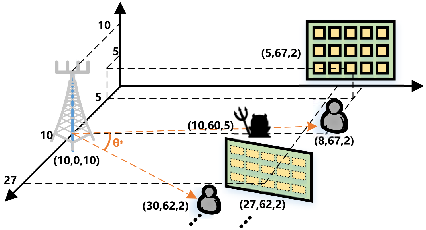
To evaluate the performance of the proposed scheme, we conduct a number of numerical evaluations in this section. The overall setup is shown in Fig. 2, we consider the base station is located at (10, 0, 10), IRSs and legitimate users are uniformly distributed around base station with a constant angle θ\theta^{*}. The first user and IRS are located at (5, 67, 5) and (8, 67, 2), respectively. Eve is located at (10, 60, 5) where in the middle between the base station and the first user. We also assume that the direct channel between the base station and users are blocked by obstacles, which implies the channel state of the base station and a user is much worse than the channel state between the IRS and the user. Specifically, the channels from base station to IRS/users/Eve are assumed to follow the distance-dependent path loss model, which can be generated by 𝒉=L0dabβ𝒉\boldsymbol{h}=\sqrt{L_{0}d_{ab}^{-\beta}}\boldsymbol{h}^{*}, where dabd_{ab} denotes the distance from location aa to location bb, and 𝒉\boldsymbol{h}^{*} is the small-scale fading component with Rician fading [34, 35]:

𝒉=KK+1𝒉LoS+1K+1𝒉NLoS,\boldsymbol{h}^{*}=\sqrt{\frac{K}{K+1}}\boldsymbol{h}^{*}_{LoS}+\sqrt{\frac{1}{K+1}}\boldsymbol{h}^{*}_{NLoS}, (43)

where 𝒉LoS\boldsymbol{h}^{*}_{LoS} and 𝒉NLoS\boldsymbol{h}^{*}_{NLoS} represent the deterministic Line-of-Sight (LoS) and Rayleigh fading/Non-LoS (NLoS) components, respectively. The LoS components are expressed as the responses of the NN-elements uniform linear array 𝒉LoS=𝒂m(θ)𝒂n(θ)H\boldsymbol{h}^{*}_{LoS}=\boldsymbol{a}_{m}(\theta)\boldsymbol{a}_{n}(\theta)^{H}. The array response of an N-element IRS can be calculated by:

𝒂m=exp(j2πλdt(m1)sinϕLoS1sinθLoS1),m=1,,M,\boldsymbol{a}_{m}=\exp\left(j\frac{2\pi}{\lambda}d_{t}\left(m-1\right)\sin\phi_{LoS_{1}}\sin\theta_{LoS_{1}}\right),m=1,...,M,
𝒂n=exp(j2πλdr(m1)sinϕLoS2sinθLoS2),n=1,,N,\boldsymbol{a}_{n}=\exp(j\frac{2\pi}{\lambda}d_{r}(m-1)\sin\phi_{LoS_{2}}\sin\theta_{LoS_{2}}),n=1,...,N,

where dtd_{t} and drd_{r} are the inter-antenna separation distance at the transmitter and receiver, ϕLoS1\phi_{LoS_{1}} and ϕLoS2\phi_{LoS_{2}} are the LoS azimuth at the base station and the IRS, and θLoS1\theta_{LoS_{1}} and θLoS2\theta_{LoS_{2}} are the angle of departure at the base station and the angle of arrival at the IRS, respectively. The rest of parameter settings are listed in Table I. Two baselines below are considered:

  • Baseline 1: Only beamforming is considered at the base station, and the IRS is not deployed in the system.

  • Baseline 2: Beamforming is considered at the base station, and only one IRS is deployed in the system.

TABLE I: Simulation Parameters
Parameter Value
Carrier frequency 2 GHz
IRS configuration Uniform rectangular array with 5 elements in a row and N/5 columns with 3λ/83\lambda/8 spacing
Path loss exponent βBU=βBE=5\beta_{BU}=\beta_{BE}=5, βBI=βIU=βIE=2\beta_{BI}=\beta_{IU}=\beta_{IE}=2, respectively
Rician channel factor KBU=KBE=0K_{BU}=K_{BE}=0, KBI=KIU=KIE=K_{BI}=K_{IU}=K_{IE}=\infty, respectively
Path loss at 1 meter L0=30dBL_{0}=-30dB
Other parameters N0=174N_{0}=-174dBm, Tx = 4, δ=0.001\delta=0.001, θ=20\theta^{*}=20^{\circ}

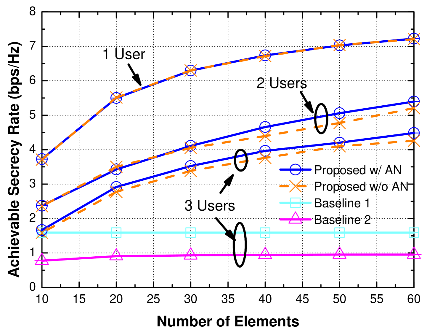
Fig. 3 shows the influence of different number of reflecting elements NN on each IRS. Due to the existence of obstacles, the LoS component is relatively poor for wireless transmissions between the base station and the user. When only one user is considered, the proposed scheme with AN has almost the same performance as the one without AN, which is is also verified in [13]. When there are 2 or more users, additional AN can help improve secrecy rate about 4-6% especially with the increase in NN. Without the assistance of IRS and AN, baseline 1 has the worst performance compared with other schemes since the direct channel between the base station and the user is blocked. For fair comparison, we change βBU=βBE=2\beta_{BU}=\beta_{BE}=2 for the beamforming scheme. The result also shows that the performance of beamforming scheme is relatively poor when there are multiple users. For baseline 2, since users are distributed further apart from each other, only one IRS cannot satisfy the requirement for secure communications.

Refer to caption
Figure 3: The achievable secrecy rate vs the number of elements (Pmax=40dBmP_{max}=40dBm).
Refer to caption
Figure 4: The achievable secrecy rate vs the number of users (Pmax=40dBmP_{max}=40dBm and N=20N=20).

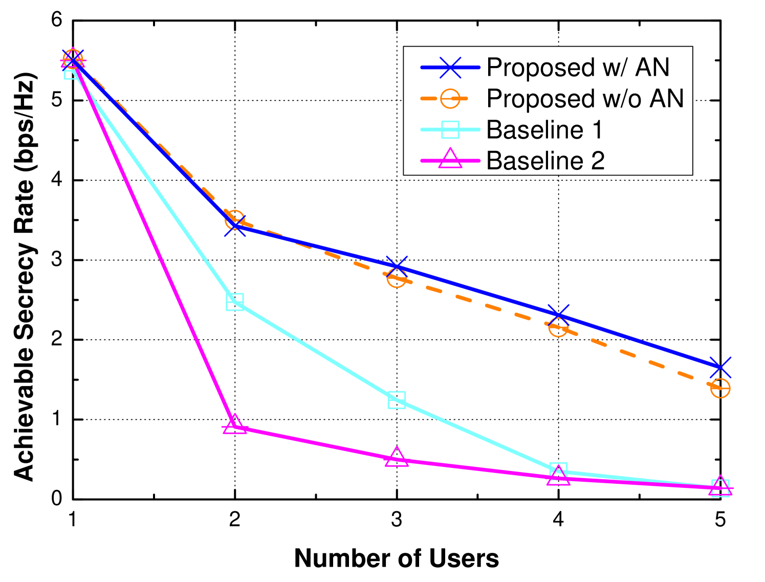
The achievable secrecy rate versus the number of users is shown in Fig. 4. As we observe, the performance of all schemes in terms of achievable secrecy rate are degrading rapidly with the increase in the number of users. When there are more than 2 users, the proposed scheme perform better than AN-disabled scheme by up to 18.9%. Here, for a fair comparison, we also set βBU=βBE=2\beta_{BU}=\beta_{BE}=2 in baseline 1. The result also shows that the beamforming scheme in baseline 1 cannot deal with multiple users scenarios. Moreover, since the distance between the IRS and users significantly influences the performance of IRS-assisted schemes, we also set up a friendly scenario for baseline 2, i.e., all users are uniformly placed on the line from (8, 67, 2) to (8, 75, 2). When only a single IRS is deployed, the performance becomes even worse than that for baseline 1. The reason is that the environmental diversity provided by the IRS is very limited. If the overall performance is considered, e.g., the sum of secrecy rate, the system still can sacrifice a part of users’ performance to achieve a better overall performance. If the worst performance in the system is considered as the objective, it becomes hard to optimize since each user matters. In this case, the algorithm tends to sacrifice the users who have the highest secrecy rate and make up for the users who have the worst secrecy rate, but the compensation is not significant enough due to the lack of environmental diversity. In this case, a poor performance is observed.

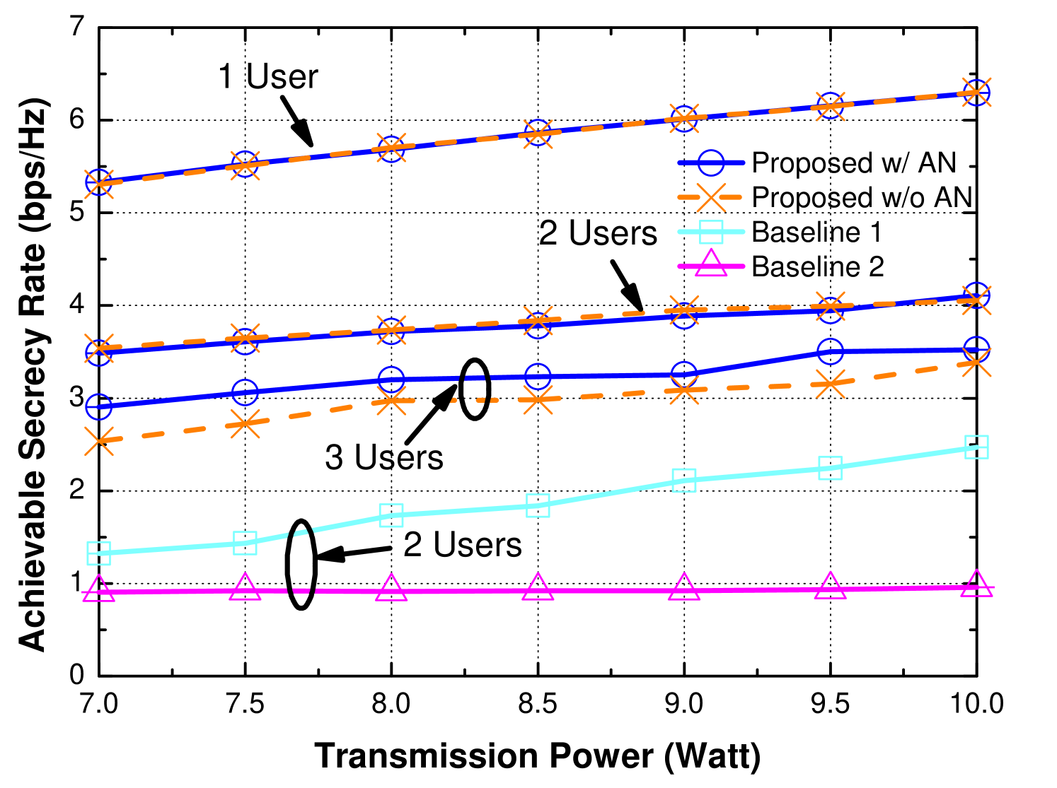
The performance of achievable secrecy rate versus transmission power is shown in Fig. 5. The maximum transmission power ranges from 7W (38.45dBm) to 10W (40dBm). With the increase in transmission power, the performance of all schemes increase linearly. Similar to the results in Fig. 4, the proposed scheme outperforms the AN-disabled scheme when there are more than 2 users in the system. To have a fair comparison, we also consider LoS channel is not blocked by obstacle and set βBU=βBE=2\beta_{BU}=\beta_{BE}=2 for baseline 1 with 2 users. However, the result shows that the performance of baseline 1 is much lower than IRS-assisted schemes. For baseline 2, since the performance is mainly limited by environmental diversity, it remains relatively steady and increases linearly from 0.9bps/Hz to 0.96bps/Hz with the increase in transmission power.

Refer to caption
Figure 5: The achievable secrecy rate vs maximum transmission power (N=30N=30).

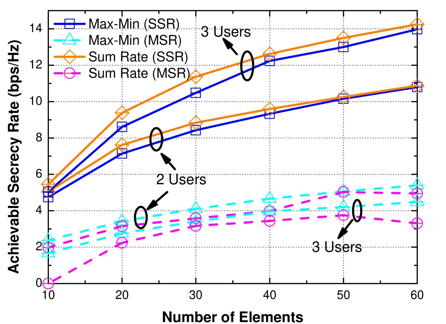
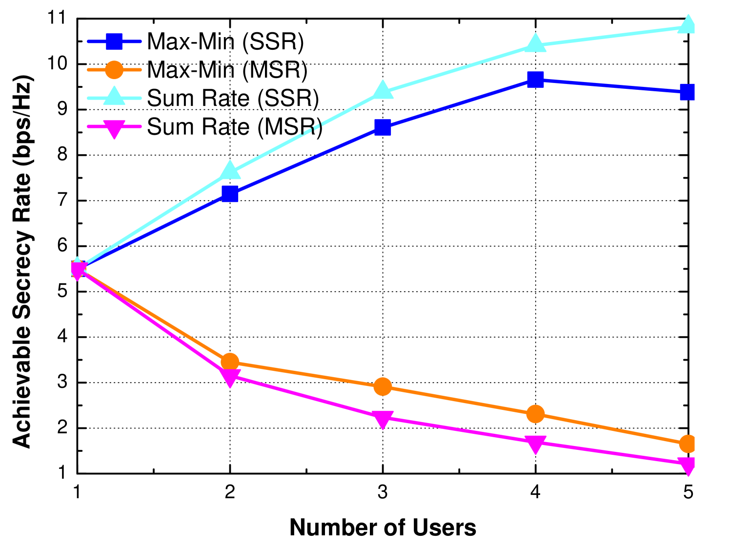
In general, overall security performance is a common objective considered in related works. To compare the performance of the max-min problem proposed in this paper with the commonly studied sum-rate maximization, we plot Fig. 6-7 to show the difference in terms of the minimum secrecy rate and the sum of secrecy rate, where the problem in (6) with constraints (C1)-(C3) can be reformulated as:

max𝝎¯,𝒛¯,𝚯¯,𝜶¯i[RiuRie]+~~~\max\limits_{\boldsymbol{\bar{\omega}},\boldsymbol{\bar{z}},\boldsymbol{\bar{\Theta}},\boldsymbol{\bar{\alpha}}}~\sum\limits_{i}[R_{i}^{u}-R_{i}^{e}]^{+} (44)
s.t.(C1)(C3).\displaystyle s.t.~~~(C1)-(C3).

Note that “MSR” and “SSR” in the legend represent the minimum secrecy rate and the sum of secrecy rate, respectively. As shown in Fig. 6, for the performance in terms of the minimum secrecy rate, the gap between two objectives can vary rapidly with different number of elements, especially for the scenarios with more users, which implies that sum-rate objective can hardly guarantee the worst secrecy rates for different users. For the performance in terms of the sum of secrecy rate, with the increase in the number of elements, the overall sum of secrecy rates of these two objective tends to converge and have similar performance. This phenomenon indicates that a max-min problem can achieve better minimum secrecy rate and also reach similar performance in overall secrecy rate for a large-scale IRS-assisted system. Meanwhile, in Fig. 7, the sum of secrecy rate increases with the number of users. Even though it can sacrifice some users’ performance to improve overall performance, the curve shows that the gain becomes less and the sum secrecy rate reaches a threshold with the increase in the number of users, which represents the maximum secrecy capacity in the system. For the gap between two different objectives, it also becomes larger with the increase in the number of users, which is reasonable since the solution space becomes larger with more users in the system, and different solutions obtained from the aforementioned objectives do impact more users.

V Conclusion

Refer to caption
Figure 6: Max-min problem vs sum-rate problem in terms of the number of elements (Pmax=40dBmP_{max}=40dBm).
Refer to caption
Figure 7: Max-min problem vs sum-rate problem in terms of the number of users (Pmax=40dBm,N=20P_{max}=40dBm,N=20).

In this paper, we have focused on physical layer security in wireless systems with IRSs, and investigated a max-min problem regarding secrecy rate under one typical eavesdropper scenario. By placing multiple collaborative IRSs in complex environment, the base station could leverage the environmental diversity to achieve significant improvement in terms of secrecy rate through joint optimization of beamforming and phase shift on the IRS. Based on our numerical evaluation, when multiple users are considered, the additional AN has been proven to effectively create interference at the eavesdropper and further improve the performance in terms of secrecy rate. Compared with sum-rate maximization studied in related works, we have found out that the performance of the proposed max-min problem converges to that of sum-rate problem in terms of the sum of secrecy rate when increasing the number of elements on IRSs. In the future, we plan to extend our study by considering a general adversary model and explore the specific collaborative protocols/mechanism among multiple IRSs.

References

  • [1] M. Chraiti, A. Ghrayeb, and C. Assi, “Achieving full secure degrees-of-freedom for the MISO wiretap channel with an unknown eavesdropper,” IEEE Transactions on Wireless Communications, vol. 16, no. 11, pp. 7066–7079, 2017.
  • [2] Q. Li, M. Hong, H.-T. Wai, Y.-F. Liu, W.-K. Ma, and Z.-Q. Luo, “Transmit solutions for MIMO wiretap channels using alternating optimization,” IEEE Journal on Selected Areas in Communications, vol. 31, no. 9, pp. 1714–1727, 2013.
  • [3] X. He and A. Yener, “MIMO wiretap channels with unknown and varying eavesdropper channel states,” IEEE Transactions on Information Theory, vol. 60, no. 11, pp. 6844–6869, 2014.
  • [4] H.-M. Wang, X. Zhang, Q. Yang, and T. A. Tsiftsis, “Secure users oriented downlink MISO NOMA,” IEEE Journal of Selected Topics in Signal Processing, vol. 13, no. 3, pp. 671–684, 2019.
  • [5] X. Guan, Q. Wu, and R. Zhang, “Intelligent reflecting surface assisted secrecy communication: Is artificial noise helpful or not?” IEEE Wireless Communications Letters, 2020.
  • [6] Y. Zou, J. Zhu, X. Wang, and V. C. Leung, “Improving physical-layer security in wireless communications using diversity techniques,” IEEE Network, vol. 29, no. 1, pp. 42–48, 2015.
  • [7] Y.-S. Shiu, S. Y. Chang, H.-C. Wu, S. C.-H. Huang, and H.-H. Chen, “Physical layer security in wireless networks: A tutorial,” IEEE wireless Communications, vol. 18, no. 2, pp. 66–74, 2011.
  • [8] F. Zhu, F. Gao, M. Yao, and H. Zou, “Joint information-and jamming-beamforming for physical layer security with full duplex base station,” IEEE Transactions on Signal Processing, vol. 62, no. 24, pp. 6391–6401, 2014.
  • [9] F. Zhu and M. Yao, “Improving physical-layer security for CRNs using SINR-based cooperative beamforming,” IEEE Transactions on Vehicular Technology, vol. 65, no. 3, pp. 1835–1841, 2015.
  • [10] M. Di Renzo, A. Zappone, M. Debbah, M.-S. Alouini, C. Yuen, J. de Rosny, and S. Tretyakov, “Smart radio environments empowered by reconfigurable intelligent surfaces: How it works, state of research, and road ahead,” arXiv preprint arXiv:2004.09352, 2020.
  • [11] M. Di Renzo, M. Debbah, D.-T. Phan-Huy, A. Zappone, M.-S. Alouini, C. Yuen, V. Sciancalepore, G. C. Alexandropoulos, J. Hoydis, H. Gacanin et al., “Smart radio environments empowered by reconfigurable ai meta-surfaces: An idea whose time has come,” EURASIP Journal on Wireless Communications and Networking, vol. 2019, no. 1, pp. 1–20, 2019.
  • [12] Q. Wu and R. Zhang, “Towards smart and reconfigurable environment: Intelligent reflecting surface aided wireless network,” IEEE Communications Magazine, 2019.
  • [13] ——, “Intelligent reflecting surface enhanced wireless network via joint active and passive beamforming,” IEEE Transactions on Wireless Communications, vol. 18, no. 11, pp. 5394–5409, 2019.
  • [14] L. Zhang, L. Yan, B. Lin, H. Ding, Y. Fang, and X. Fang, “Augmenting transmission environments for better communications: tunable reflector assisted mmwave wlans,” IEEE Transactions on Vehicular Technology, vol. 69, no. 7, pp. 7416–7428, 2020.
  • [15] L. Zhang, L. Yan, B. Lin, Y. Fang, and X. Fang, “Tunable reflectors enabled environment augmentation for better mmwave wlans,” in 2019 IEEE/CIC International Conference on Communications in China (ICCC).  IEEE, 2019, pp. 7–12.
  • [16] M. Cui, G. Zhang, and R. Zhang, “Secure wireless communication via intelligent reflecting surface,” IEEE Wireless Communications Letters, vol. 8, no. 5, pp. 1410–1414, 2019.
  • [17] X. Yu, D. Xu, and R. Schober, “Enabling secure wireless communications via intelligent reflecting surfaces,” arXiv preprint arXiv:1904.09573, 2019.
  • [18] L. Dong and H.-M. Wang, “Secure MIMO transmission via intelligent reflecting surface,” IEEE Wireless Communications Letters, 2020.
  • [19] B. Lyu, D. T. Hoang, S. Gong, D. Niyato, and D. I. Kim, “IRS-based wireless jamming attacks: When jammers can attack without power,” arXiv preprint arXiv:2001.01887, 2020.
  • [20] D. Xu, X. Yu, Y. Sun, D. W. K. Ng, and R. Schober, “Resource allocation for secure irs-assisted multiuser MISO systems,” in 2019 IEEE Globecom Workshops (GC Wkshps).  IEEE, 2019, pp. 1–6.
  • [21] B. Zheng and R. Zhang, “Intelligent reflecting surface-enhanced ofdm: Channel estimation and reflection optimization,” IEEE Wireless Communications Letters, vol. 9, no. 4, pp. 518–522, 2019.
  • [22] J. Li, K. Xue, D. S. Wei, J. Liu, and Y. Zhang, “Energy efficiency and traffic offloading optimization in integrated satellite/terrestrial radio access networks,” IEEE Transactions on Wireless Communications, vol. 19, no. 4, pp. 2367–2381, 2020.
  • [23] M. Razaviyayn, “Successive convex approximation: Analysis and applications,” 2014.
  • [24] Y. Sun, D. W. K. Ng, Z. Ding, and R. Schober, “Optimal joint power and subcarrier allocation for full-duplex multicarrier non-orthogonal multiple access systems,” IEEE Transactions on Communications, vol. 65, no. 3, pp. 1077–1091, 2017.
  • [25] A. Alvarado, G. Scutari, and J.-S. Pang, “A new decomposition method for multiuser DC-programming and its applications,” IEEE Transactions on Signal Processing, vol. 62, no. 11, pp. 2984–2998, 2014.
  • [26] M. Simchowitz, “Course notes for ee227c (spring 2018): Convex optimization and approximation,” 2018.
  • [27] Z.-Q. Luo, W.-K. Ma, A. M.-C. So, Y. Ye, and S. Zhang, “Semidefinite relaxation of quadratic optimization problems,” IEEE Signal Processing Magazine, vol. 27, no. 3, pp. 20–34, 2010.
  • [28] W.-K. K. Ma, “Semidefinite relaxation and its applications in signal processing and communications,” IEEE SIGNAL PROCESSING MAGAZINE, vol. 1053, no. 5888/10, 2010.
  • [29] W.-K. Ma, “Semidefinite relaxation and its applications in signal processing and communications,” MIIS Tutorial, July 2012.
  • [30] “SeDuMi Software,” http://sedumi.ie.lehigh.edu/, accessed September 1, 2020.
  • [31] M. Grant and S. Boyd, “CVX: Matlab software for disciplined convex programming, version 2.1,” 2014.
  • [32] A. A. Nasir, D. T. Ngo, X. Zhou, R. A. Kennedy, and S. Durrani, “Joint resource optimization for multicell networks with wireless energy harvesting relays,” IEEE Transactions on Vehicular Technology, vol. 65, no. 8, pp. 6168–6183, 2015.
  • [33] T. Wang and L. Vandendorpe, “Successive convex approximation based methods for dynamic spectrum management,” in 2012 IEEE International Conference on Communications (ICC).  IEEE, 2012, pp. 4061–4065.
  • [34] H. Han, J. Zhao, D. Niyato, M. Di Renzo, and Q.-V. Pham, “Intelligent reflecting surface aided network: Power control for physical-layer broadcasting,” arXiv preprint arXiv:1910.14383, 2019.
  • [35] Y. Han, W. Tang, S. Jin, C.-K. Wen, and X. Ma, “Large intelligent surface-assisted wireless communication exploiting statistical CSI,” IEEE Transactions on Vehicular Technology, vol. 68, no. 8, pp. 8238–8242, 2019.