Set based velocity shaping for robotic manipulators
Abstract
We develop a new framework for trajectory planning on predefined paths, for general N-link manipulators. Different from previous approaches generating open-loop minimum time controllers or pre-tuned motion profiles by time-scaling, we establish analytic algorithms that recover all initial conditions that can be driven to the desirable target set while adhering to environment constraints. More technologically relevant, we characterise families of corresponding safe state-feedback controllers with several desirable properties. A key enabler in our framework is the introduction of a state feedback template, that induces ordering properties between trajectories of the resulting closed-loop system. The proposed structure allows working on the nonlinear system directly in both the analysis and synthesis problems. Both offline computations and online implementation are scalable with respect to the number of links of the manipulator. The results can potentially be used in a series of challenging problems: Numerical experiments on a commercial robotic manipulator demonstrate that efficient online implementation is possible.
I Introduction
In recent years, there has been growing demand for safer robots, especially in the context of Industry 4.0 and environments containing fragile agents such as humans [1]. Robots face challenges in their integration with the workforce[2], in particular related to safety, inclusion of temporal specifications, and reliability [3], [4].
Planning of robotic manipulators has received much attention over the years with a wide range of approaches available [5]. The challenge lies in computing collision free paths in a nonconvex environment, and in a sufficiently fast time [6].
Established approaches to producing safe controllers aim to place constraints on speed, momentum and potential collision energies of the system in order to ensure safety [7, 8, 9]. These controllers rely on the trajectory planner found within the typical motion controller.
Trajectory planning, which is the focus of this article, is concerned with shaping the velocity profile as the robot moves from one configuration to another. Typically, the enforcement of hard constraints on the system dynamics is imposed on the velocity profile, see, e.g., [10, 11, 12, 13], where an optimal velocity profile is calculated. These optimal approaches have also been extended to account for other state dependent and time dependent constraints [14], [15].
Optimal control approaches, a version of which concerns time scaling algorithms, produce a single optimal trajectory fed to a robot to execute the desired motion. These algorithms have been successfully utilised in the last decades, however, they inevitably come with shortcomings, for example: They are discontinuous, they are restricted to kinodynamic planning problems that specify a unique acceptable velocity for the end of the path, and offer little ability to adapt the profile along the path, as most versions generate open-loop controllers.
To address these shortcomings, we investigate a larger class of state-feedback controllers, using the same reasoning for projecting the dynamics of the robotic manipulator on a prespecified path as in the traditional aforementioned approaches. However, instead of finding time-optimal solutions for the zero initial condition, we characterise the whole set of admissible states, namely, the distance traversed in the path and its pseudo velocity, that can reach a target set in finite time and satisfy constraints throughout.
By projecting the dynamics on a path, any -degree of freedom (DOF) manipulator is represented by a constrained double integrator. The control input corresponds to the pseudo acceleration across the path and is subject to non linear and nonconvex constraints, induced mainly by the physical constraints on the torques of the actuators. At this stage additional constraints can be imposed, related, e.g., to potential collision energy, time constraints, or constraints relating to end effector forces that could prove useful in high precision applications, e.g., machining [9], [16].
Technically, rather than solving a single optimal control problem as, e.g., in [10, 11], our main objective is to answer the question: Can we compute the subset of states for which a state feedback controller exists driving the system to a target set without violating any constraints in finite time?
Sets with these properties are called reach-avoid sets [17] [18]. Many issues related to robots and path planning are often naturally expressed in the context of reach-avoid problems, examples include motion planning, collision avoidance, space vehicle docking, and object tracking applications [19, 20, 21, 22]. To the best of our knowledge, this is the first time it is suggested to cast the kinodynamic planning problem as a reach-avoid set computation.
Illustrative Example 1
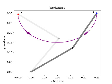
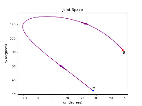
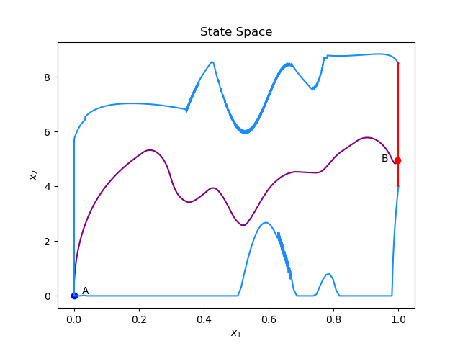
Figures 1(a) - 1(c) depict with purple color the same motion of a two link manipulator moving from point A to point B in three different spaces. The end effector work space is shown in Figure 1(a), the space of joints is shown in Figure 1(b). In the general case the joint space can be dimensional, depending upon the number of actuators on the robot. The state space shown in Figure 1(c) is always two dimensional, having as states the pseudo distance of the path travelled () and the end effector pseudo velocity (). We focus on designing state feedback controllers in this space (Figure 1(c)). We can incorporate and visualise additional constraints based on the system state (configuration and speed) with blue. The target set is depicted in red in Figure 1(c).
Highly relevant for safety-critical systems, reach-avoid problems are not trivial. Efficient solutions depend on the nature of the system, with several techniques available for a variety of system types [23, 24, 25]. In our case, we are exploiting the monotonicity of the projected trajectories with respect to a novel parameterisation of the control input. This parameterisation allows ordering relations between generated closed-loop trajectories to be established in terms of both the initial conditions and the control input. These observations constitute the building blocks of an algorithmic procedure that recovers an approximation of the largest reach-avoid set. Compared to interesting related approaches [26], [27], our work deals directly with the nonlinear dynamics and constraints, and constructs the boundaries of the reach-avoid set using a combination of extreme trajectories. Thus, there is no added conservatism caused by the linearisation of dynamics.
We also establish set-based state feedback controllers, induced by the parameterisation of the control strategy. Taking into account the preference for continuous, smooth, and robust state feedback control reducing wear on actuators, we establish general properties the control template must satisfy, and show how simple, Lipschitz continuous, continuous, and sliding mode-like controllers can be established. Last, we apply our framework to numerical experiments on commercial robotic manipulators, and discuss practical considerations in algorithmic implementation to show the efficacy of our approach. Preliminary ideas on computing reach-avoid sets for the studied problem are reported in [28]. In comparison, we formally show continuity properties of the suggested control template, establish analytic algorithms on computations of the reach-avoid set, propose new families of stabilizing feedback controllers, highlight practical challenges in implementation, and perform a formal comparison of our results with the conventional time optimal control approach.
Section II discusses preliminaries. In Section III we introduce the problem and the control input parameterisation, and establish the Lipshitz properties of the closed-loop system dynamics. Section IV establishes ordering relations between generated trajectories, while section V illustrates in detail the algorithmic procedure for producing the reach-avoid set. Section VI deals with the characterisation and implementation of families of safe state feedback controllers. Section VII presents examples of the algorithms running on a Python based simulation using the model for the Universal Robots UR5 [29] available within the Matlab file exchange [30]. Conclusions are drawn in Section VIII. For ease of exposition the proofs are placed in the Appendix.
II Preliminaries
Notation: For a vector , is its 2-norm and its element. For a vector with a label in its subscript, we write its element as . We denote sets, e.g., , with capital letters in italics. For a set , , and denote its convex hull, boundary and interior respectively. The ball centered at zero with radius is denoted by . The distance of a point from a compact set . Vector inequalities hold elementwise.
The motion of -link manipulators can be described using standard Lagrangian dynamics by
where corresponds to joint positions and collects the actuator torques for each joint. The matrices , are the inertial and centrifugal/Coriolis matrices respectively. The gravitational force effects are represented by . The matrix and vector functions , and are globally Lipschitz, [31, 32, 33].
The Lagrangian dynamics can be projected to path dynamics: The first step is to consider an end effector path described by a function known as a path parameterisation where is a scalar representing each configuration of the robot as it moves along the path.
Assumption 1
The path parameterisation is two times differentiable. Moreover, , for and a constant positive number .
Assumption 1 is not restrictive and is common in the literature [10, 11], [34]. Intuitively, it requires that the configuration must be able to change such that the end effector can traverse a path in finite time.
The parameterised system becomes where , , , are the transformed vectors, and describes the torques and forces produced by the actuators. We define . The torques are limited by the actuator dynamics as where and describe the maximum torque that can be generated in either direction. The element, , of the vectors within the parameterised system generates constraints of the form
| (1) |
Assumption 2
The state-dependent constraint bounds and are locally Lipschitz in x for the whole range of admissible motions, for all .
Assumption 2 is not restrictive for electrical motors due to their continuous relationships between torque and speed, see, e.g., [35] [36, Chapter 10].
Rearranging (1), the limits on possible accelerations from any given state can be formed. We set , for , and , for . The case of zero inertia points, i.e., when , for one or more indices is taken into account by posing algebraic constraints on [34] of the form By grouping the above constraints, we can write
| (2) |
where
| (3) | ||||
| (4) |
The projected system is a double integrator
| (5) |
with , . The state feedback accounts for the acceleration , whose admissible range is state-dependent (2). The solution of (5) at time starting from an initial condition , under the control function is
| (6) |
The state and input constraints are where , with , . Moreover, , and . We note that within our framework we can incorporate additional constraints. We assume we can eventually describe all constraints via two functions and , representing upper and lower bounds respectively. This leads to the description of the constraint set
| (7) |
The overall state (we note and input constraints are
| (8) |
Assumption 3
The functions and are semi-differentiable continuous bijections.
We note Assumption 3 is indeed somewhat restrictive, as, for example, it does not allow islanding. Nevertheless, it covers many realistic and challenging cases, including polynomial and trigonometric constraints.
III Control parameterisation and properties
In this section, we propose a parameterisation of the state feedback controller as a convex combination of the state dependent input constraints. The generally non-restrictive Assumptions 1, 2 allow us to characterize the parameterisation with Lipschitz continuity, which constitutes our first main technical result. Preliminary results and the proof of Proposition 1 can be found in the Appendix.
Proposition 1
The functions , are locally Lipschitz continuous in .
In agreement with approaches in the literature [10], [34], we set as the input variable. We build all subsequent results in the following parameterisation of the control law via the actuation level function as follows
| (9) |
The following result is a consequence of Proposition 1.
Corollary 1
We consider target sets of the form
| (12) |
where and . Given a particular choice of the actuation level function (9) and an initial condition , the solution of (10) is where . Correspondingly, the solution of the backwards dynamics (11) is .
Definition 1
IV Ordering properties of closed-loop trajectories
We collect the admissible trajectories of the closed loop system in the forward and backwards direction in the sets
| (14) |
| (15) |
respectively. In the remainder, and to discuss trajectories without needing to specify the direction in which they are formed, we write . We define intervals . The slice of a set on an interval is
| (16) |
The mapping (16) is valid also when is a singleton. In this case, we write for simplicity .
Lemma 1
Let . Consider the slice , two states such that , and a constant actuation level . Then,
Lemma 2
Let . Consider two states such that . Consider two fixed actuation levels . Then, the trajectories can intersect at most once in , i.e., either , for some , or .
A straightforward consequence of Lemma 2 is that for any two trajectories evolving from a single state with different constant actuation levels the one with the higher actuation level will remain above the other for the duration of the motion. Specifically, for any , any it holds that , where , . This is summarised in the following corollary.
Corollary 2
Moreover, Lemma 2 implies that in the case where , we have for any two trajectories , where , lie on a slice where such that and .
V Approximation of the maximal Reach-avoid set
We first define the hypograph and epigraph of a set respectively
We also define the set-valued operation that returns the ‘leftmost’ state of a trajectory in
The sets representing the upper and lower boundaries of the (7) are defined below
| (17) | ||||
| (18) |
The results of Section IV lay the foundation for the development of the reach avoid set computation, outlined in Algrorithm 1. Initially, the two trajectories and , produced from backward integration of the extreme points of , are computed in Lines 3 and 5 respectively. We denote with and the intersections of these trajectories with the constraint set (Lines 4, 6), with , defining the interval (12). Lines 7, l0 and 13 represent the different cases that can occur, depending on where and lie. Figure 2 illustrates all possible situations: Line 7 covers Figure 2(a), where are in . In this case no additional computations are needed as . On the other hand, the lower bound needs to be extended to obtain . Line 10 covers Figure 2(b). In this case, the lower bound is complete, however, the upper bound possibly needs to be modified. Lines 13-21 cover the remaining cases shown in Figures 2(c) - 2(f), that occur when and do not intersect the same boundary or . For these instances, the extend operation is applied, which is described in detail below in Algorithm 2. After all the relevant extensions have been made Line 22 returns which is constructed as the intersection of the sets , and .
We note that the target set is the only admissible exit facet, i.e., the area of the boundary where the trajectory will escape in finite time under appropriate control . Several existing works on control-to-facet strategies focus on non-linear hybrid systems with sets defined by simplices or other simple polynomial descriptions of the set boundaries [37, 38, 39].
V-A Extension of bounds of
The operation extend(, , , ) is utilised in Algorithm 1 on Lines 8, 11, 15, and 19. We use to denote either the lower or the upper boundary, i.e., and are defined by (17) (18). The operation returns a curve that constrains any trajectory , with , when is suitably chosen. The set is effectively formed as a union of extreme trajectories and segments of by applying the backward dynamics (11). To describe the proposed procedure we define Bouligand’s tangent cone, see, e.g., [40, p. 122].
Definition 3
The tangent cone of a vector to (7) is
| (19) |
Definition 4
Consider a state and the system dynamics (10) , with . We define the set
| (20) |
Utilising (19), (20), we can write the geometric condition that verifies whether there exists an admissible input for a state that allows it to remain in as follows
| (21) |
In our setting, the boundary of is defined either on or . Let us consider the equations (17) and (18). The functions are semi-differentiable. Taking into account dynamics (10), each vector in the set has a nonnegative first element, i.e., . Consequently, in the set (20) it is sufficient to consider only the right-derivative of and in order to verify (21). We write the right derivative of the upper and lower constraint curves as
| (22) | |||
| (23) |
This is computationally convenient, allowing us to define a half-space including the set of vectors from (19) that can possibly intersect (20). The resultant half-spaces can be explicitly defined as
| (24) | ||||
| (25) |
Lemma 3
We consider a partition that will be later used to characterise the constraint curve where (21) is satisfied.
Lemma 4
Definition 5
We partition the interval in an ordered set of intervals , , , constructed from two sets, namely, and . Moreover, , with , for all and
We note any two intervals , are adjacent to each other and . Moreover, for any , if , then and vice versa.
Illustrative Example 2
Figure 3 focuses on the part enclosed by the rectangle in Figure 2(e). It illustrates a partition according to Definition 5, showing how the section in is extended. We represent with with green and red dotted lines respectively. The cones generated by 20, evaluated at two states , are represented with purple vectors. The halfspaces , 24, which in this case coincide with the tangent cones and (19) are shown in grey. We observe that for any in an interval , the system can avoid crossing the boundary. On the other hand, for any in , there is no control action preventing crossing .
As highlighted in Example 2, the boundary or often does not belong in its entirety to the reach avoid set, thus, a modification is needed. The procedure, called extend, is presented in Algorithm 2. Given the set of intervals for which condition holds as in Lemma 4, Algorithm 2 either adds the whole interval to the set or propagates the closed-loop dynamics backwards in order to form a curve that will serve as the upper or lower bound of the computed set in Algorithm 1.
Lines 5 and 17 of Algorithm 2 separate the cases where and . When (Line 9), the entire interval is added to the reach avoid set boundary. Lines 11-14 add a parts of the generated trajectory and existing constraint curve defined by . Line 16 represents the case where only an extreme trajectory is added to the set . When (Line 19) an step change from the boundary is performed, leading to the trajectory generation in Line 20. The following central result establishes that Algorithm 1 returns a reach-avoid set, in finite time.
VI Controller design
We turn our attention to the control problem, namely, constructing safe state-feedback mechanisms. First, we characterise the generic properties the controller should have so that any state in can be transferred to the target set in finite time without violating state and input constraints. Let us denote the upper and lower boundary of the reach avoid set by and respectively.
Theorem 2
The control parameterisation above is quite general. A possible realisation of (28) is to consider two locally Lipschitz functions and , with , . The continuous actuation level function is
| (29) |
We note that if we use the upper and lower bounds of to define and respectively, a valid controller can be defined as .
This is a convex linear mapping between the upper an lower bounds.
It is straightforward to see that this choice satisfies all conditions (28) of Theorem 2, excluding the Lipschitz continuity of . Indeed, due to the formation of the bounds detailed in Algorithm 1, there may be discontinuities if steps are used in the production of the boundaries. A practical way to make these bounds continuous, and therefore utilise the aforementioned simple controller, is to approximate the reach-avoid set bounds by (piecewise) polynomial functions.
Additionally, our framework captures a family of sliding mode-like controllers [41].
To elaborate, a special case in (29) can be retrieved by setting , leading to the simplified actuation level function
| (30) |
We note the resulting controller does not present a continuous control but rather a bang bang style controller, that is prone to chattering [34]. However, it can be the basis for a sliding mode control strategy: We may define the function , where represents the system dynamics as given in Definition 4 and . By a suitable choice of , if a parameter can be found such that for all , the controller meets all conditions for sliding mode operation by choosing
| (31) |
VII Numerical experiment
In this section we illustrate the established framework, in terms of reach-avoid set computation and control implementation. Subsections VII.A, VII.B deal with practical considerations in implementation, while subsection VII.C provides the simulation results.
VII-A Digital implementation
We consider the issue of sampling in the implementation of the state feedback and computation of trajectories forming the reach avoid set (Algorithms 1, 2). The solution of system (5) piecewise constant inputs is analytic, that is, for any we have
or,
Sampling time should be chosen to be small enough in order to approximate sufficiently a continuous-time controller. Input can be enforced to be admissible in , since is by construction Lipschitz continuous in . To this purpose, for any two states and considering the Lipschitz constants , so that and , the following inequalities should hold
| (32) |
VII-B Approximation of Constraint Curves
The partition in Lemma 4 requires finding the roots of the function (27). By continuity of , this can be done solving conditions and ,
with if is in and if is in . Solving above equations requires non-straightforward application of numerical methods on nonlinear functions, while in practice boundary values are evaluated at a finite number of states rather than providing analytical expressions [42]. To tackle this challenge, we can approximate with a polynomial function so that
for all states belonging in and , by solving a constrained least squares problem.
To improve approximation accuracy, one can typically increase the order of the approximating polynomial, or calculate piecewise polynomial approximations.
VII-C Results
We apply our framework to the two DOF planar manipulator setup illustrated in Figure 1(a)-1(c), and the commercially available Universal robot UR5 [43]. The UR5 simulation data are detaild below, where the two DOF manipulator setting is in Appendix A. The UR5 manipulator consists of six joints and respective actuators, for which and . We define a straight line path in the joint space as where , . The torque limitations along with the path description allow the computation of the path dynamics and , (3), (4). We assume additional inequality constraints translated in the state space , . We apply piecewise constant inputs , following the analysis Section VII.A. To compensate for the lack of knowledge of the Lipschitz constant for the state feedback, we consider modified maximum acceleration and deceleration bounds, so that the controller is defined as , where and . The modified input equation creates a buffer of 5% the difference between the limits to allow for the case where may decrease or may increase over the sampling time, and is consistent with the effect the Lipschitz constant has on the bounds (32).
The target set (12) is . The shaded region in Figure 4 represents the reach avoid set calculated via Algorithm 1, with the target set denoted in red. In this instance, we identify two intervals (Definition 5) for the lower bound and 167 intervals for the upper bound with the value of set to 0.1 for both boundaries.
To showcase a specific control trajectory, we set . We apply two different control strategies: The first concerns the state feedback controller described by the actuation level function in (29) with , . The second is the open-loop time optimal control [34]. To compute the time optimal path we target a final state of .
The closed loop trajectories of the two chosen controllers is shown in Figure 5. It is worth observing the reach avoid set contains both the time optimal trajectory as well as the state feedback controller. Moreover, we note the form of and can be varied to affect the shape of the state feedback trajectory. The computation times for each case are in Table I. Both control implementation and simulations are written in python, and ran on a standard laptop with a 7th gen intel core i5 processor.
The potential of our approach is shown in the average computation time for a single step of the feedback control strategy. It is also worth noting that the computation time for the reach avoid set on the UR5 added to the trajectory generation is faster than computing the time optimal control alone.
| Robot | UR5 | Two DOF Planar |
|---|---|---|
| Time optimal controller | s | s |
| Controller (29) computation time | s | s |
| Sampling period T for (29) | s | s |
| Reach avoid set computation | 60.3 s | 9.6 s |
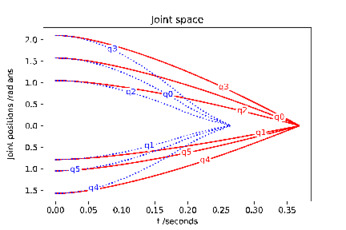
The time response of the UR5 in the joint space is shown in Figure 6. Unsurprisingly, the time optimal control is faster.
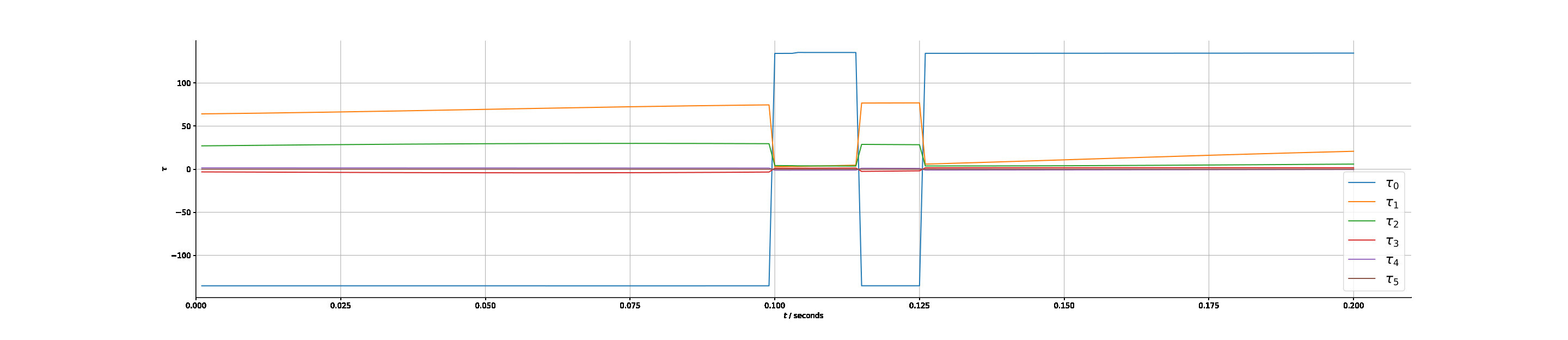
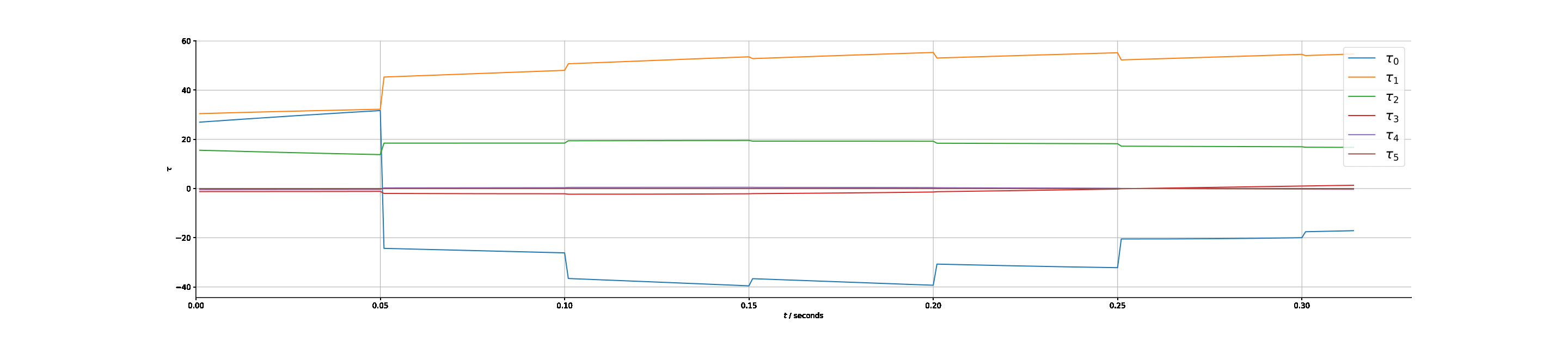
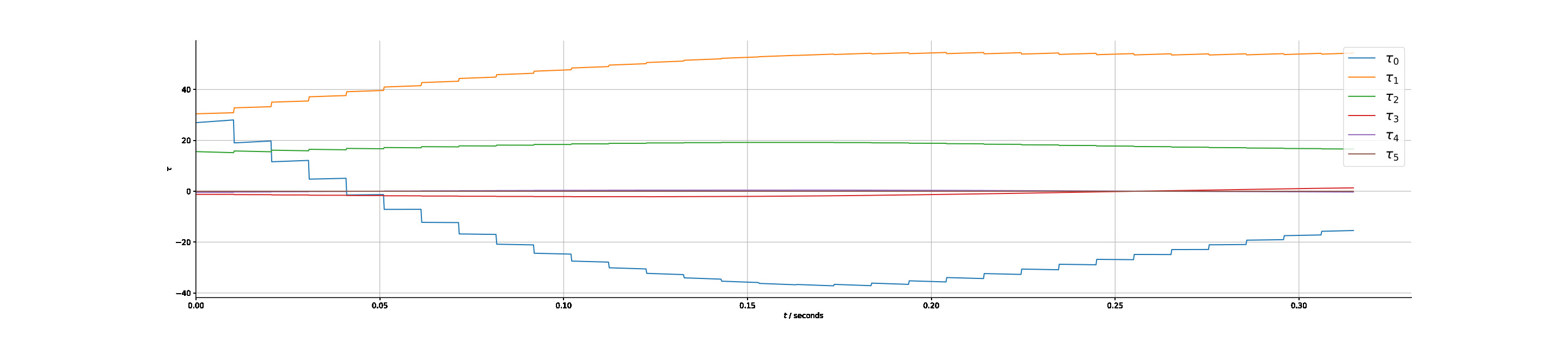
The torque response for the time optimal and the state feedback methods are given in Figures 7, 8 respectively. It is clear that the time optimal control leads to switching between maximum and minimum acceleration for at least one actuator, exhibiting large instantaneous variations. In this instance there are two switches, however in the general case there can be several, contributing to the wearing of actuators and possibly leading to additional steps for shaping the control input. In contrast, the state feedback response gives a naturally Lipschitz continuous response through the application of equation (29) in choosing the actuation level to apply. A real time implementation is indeed possible using conventional computing resources as illustrated in Figure 8(a). Nevertheless, the control response can be made smoother with a smaller sampling period as shown in Figure 8(b), which would be implementable, e.g., using embedded hardware implementation.
;
;
;
VIII Conclusions
We explored the trajectory planning problem for robotic manipulators using a well established methodology from a different angle. We formulated and addressed the problem of finding safe state-feedback controllers as a reach-avoid problem in the projected path dynamics using ordering properties of closed-loop trajectories under a suitable parameterisation of the control law. The established algorithm is practicable and terminates in finite time, while numerical experiments with a commercial manipulator show the method works well. The feedback mechanism as well the scalability of the approach suggest that the method could be potentially be used in problems in safety, e.g., in collaborative robotics. Our future work will focus on using the established framework as a building block on composition of trajectories between different paths with motion primitives, using the inherent flexibility offered, with the ultimate aim to address the path planning problem. Moreover, we aim to relax some of the assumptions on the shapes of the constraint and target sets posed herein, effectively increasing the generality of our approach.
References
- [1] V. Villani, F. Pini, F. Leali, and C. Secchi, “Survey on human–robot collaboration in industrial settings: Safety, intuitive interfaces and applications,” Mechatronics, vol. 55, pp. 248–266, 2018.
- [2] J. E. Michaelis, A. Siebert-Evenstone, D. W. Shaffer, and B. Mutlu, in Proceedings of the 2020 CHI Conference on Human Factors in Computing Systems, 2020, pp. 1–12.
- [3] E. M. E. Alegue, “Human-robot collaboration with high-payload robots in industrial settings,” in IECON 2018-44th Annual Conference of the IEEE Industrial Electronics Society. IEEE, 2018, pp. 6035–6039.
- [4] L. Kunze, N. Hawes, T. Duckett, M. Hanheide, and T. Krajník, “Artificial intelligence for long-term robot autonomy: A survey,” IEEE Robotics and Automation Letters, vol. 3, no. 4, pp. 4023–4030, 2018.
- [5] S. M. LaValle, Planning algorithms. Cambridge university press, 2006.
- [6] A. Völz and K. Graichen, “A predictive path-following controller for continuous replanning with dynamic roadmaps,” IEEE Robotics and Automation Letters, vol. 4, no. 4, pp. 3963–3970, 2019.
- [7] L. Joseph, V. Padois, and G. Morel, “Towards x-ray medical imaging with robots in the open: safety without compromising performances,” in 2018 IEEE International Conference on Robotics and Automation (ICRA). IEEE, 2018, pp. 6604–6610.
- [8] ——, “Experimental validation of an energy constraint for a safer collaboration with robots,” in International Symposium on Experimental Robotics. Springer, 2018, pp. 575–583.
- [9] R. Rossi, M. P. Polverini, A. M. Zanchettin, and P. Rocco, “A pre-collision control strategy for human-robot interaction based on dissipated energy in potential inelastic impacts,” in 2015 IEEE/RSJ International Conference on Intelligent Robots and Systems (IROS). IEEE, 2015, pp. 26–31.
- [10] Kang Shin and N. McKay, “Minimum-time control of robotic manipulators with geometric path constraints,” IEEE Transactions on Automatic Control, vol. 30, no. 6, pp. 531–541, 1985.
- [11] J. E. Bobrow, S. Dubowsky, and J. S. Gibson, “Time-optimal control of robotic manipulators along specified paths,” The international journal of robotics research, vol. 4, no. 3, pp. 3–17, 1985.
- [12] F. Pfeiffer and R. Johanni, “A concept for manipulator trajectory planning,” IEEE Journal on Robotics and Automation, vol. 3, no. 2, pp. 115–123, 1987.
- [13] J. M. Hollerbach, “Dynamic scaling of manipulator trajectories,” in 1983 American Control Conference. IEEE, 1983, pp. 752–756.
- [14] S. Ma, “Time-optimal control of robotic manipulators with limit heat characteristics of the actuator,” Advanced Robotics, vol. 16, no. 4, pp. 309–324, 2002.
- [15] Z. Shiller, “Time-energy optimal control of articulated systems with geometric path constraints,” 1996.
- [16] A. Olabi, R. Béarée, O. Gibaru, and M. Damak, “Feedrate planning for machining with industrial six-axis robots,” Control Engineering Practice, vol. 18, no. 5, pp. 471–482, 2010.
- [17] J. D. Gleason, A. P. Vinod, and M. M. K. Oishi, “Underapproximation of reach-avoid sets for discrete-time stochastic systems via lagrangian methods,” in 2017 IEEE 56th Annual Conference on Decision and Control (CDC), 2017, pp. 4283–4290.
- [18] B. Landry, M. Chen, S. Hemley, and M. Pavone, “Reach-avoid problems via sum-or-squares optimization and dynamic programming,” in 2018 IEEE/RSJ International Conference on Intelligent Robots and Systems (IROS). IEEE, 2018, pp. 4325–4332.
- [19] J. F. Fisac, M. Chen, C. J. Tomlin, and S. S. Sastry, “Reach-avoid problems with time-varying dynamics, targets and constraints,” in Proceedings of the 18th international conference on hybrid systems: computation and control, 2015, pp. 11–20.
- [20] L. Shamgah, T. G. Tadewos, A. Karimoddini, and A. Homaifar, “Path planning and control of autonomous vehicles in dynamic reach-avoid scenarios,” in 2018 IEEE Conference on Control Technology and Applications (CCTA). IEEE, 2018, pp. 88–93.
- [21] B. HomChaudhuri, M. Oishi, M. Shubert, M. Baldwin, and R. S. Erwin, “Computing reach-avoid sets for space vehicle docking under continuous thrust,” in 2016 IEEE 55th Conference on Decision and Control (CDC). IEEE, 2016, pp. 3312–3318.
- [22] N. Kariotoglou, D. M. Raimondo, S. Summers, and J. Lygeros, “A stochastic reachability framework for autonomous surveillance with pan-tilt-zoom cameras,” in 2011 50th IEEE Conference on Decision and Control and European Control Conference. IEEE, 2011, pp. 1411–1416.
- [23] S. Summers and J. Lygeros, “Verification of discrete time stochastic hybrid systems: A stochastic reach-avoid decision problem,” Automatica, vol. 46, no. 12, pp. 1951–1961, 2010.
- [24] S. N. Krishna, A. Kumar, F. Somenzi, B. Touri, and A. Trivedi, “The reach-avoid problem for constant-rate multi-mode systems,” in International Symposium on Automated Technology for Verification and Analysis. Springer, 2017, pp. 463–479.
- [25] L. Shamgah, T. G. Tadewos, A. Karimoddini, and A. Homaifar, “A symbolic approach for multi-target dynamic reach-avoid problem,” in 2018 IEEE 14th International Conference on Control and Automation (ICCA). IEEE, 2018, pp. 1022–1027.
- [26] Q. Pham, “A general, fast, and robust implementation of the time-optimal path parameterization algorithm,” IEEE Transactions on Robotics, vol. 30, no. 6, pp. 1533–1540, 2014.
- [27] H. Pham and Q. Pham, “A new approach to time-optimal path parameterization based on reachability analysis,” IEEE Transactions on Robotics, vol. 34, no. 3, pp. 645–659, 2018.
- [28] R. McGovern and N. Athanasopoulos, “Kinodynamic planning for robotic manipulators using set-based methods,” in 2022 European Control Conference (ECC). IEEE, 2022, pp. 1309–1314.
- [29] U. Robots, “Universal Robots Website,” https://www.universal-robots.com/, 2021, [Online; accessed 14-July-2021].
- [30] P. M. Kebria, S. Al-wais, H. Abdi, and S. Nahavandi, “Kinematic and dynamic modelling of UR5 manipulator,” in 2016 IEEE International Conference on Systems, Man, and Cybernetics (SMC). IEEE, oct 2016. [Online]. Available: https://doi.org/10.1109%2Fsmc.2016.7844896
- [31] J.-Y. Choi, J. Uh, and J. S. Lee, “Iterative learning control of robot manipulator with i-type parameter estimator,” in Proceedings of the 2001 American Control Conference.(Cat. No. 01CH37148), vol. 1. IEEE, 2001, pp. 646–651.
- [32] F. Bouakrif, D. Boukhetala, and F. Boudjema, “Velocity observer-based iterative learning control for robot manipulators,” International Journal of Systems Science, vol. 44, no. 2, pp. 214–222, 2013.
- [33] M. de Mathelin, R. Lozano, and D. Taoutaou, “Commande adaptative et applications,” Hermès Science, 2001.
- [34] K. M. Lynch and F. C. Park, Modern Robotics, 2017.
- [35] E. Hughes, J. Hiley, K. Brown, and I. M. Smith, Hughes Electrical and Electronic Technology, 07 2021.
- [36] M. W. Spong, S. Hutchinson, and M. Vidyasagar, Robot Modeling and Control, 11 2005.
- [37] L. Habets, P. J. Collins, and J. H. van Schuppen, “Reachability and control synthesis for piecewise-affine hybrid systems on simplices,” IEEE Transactions on Automatic Control, vol. 51, no. 6, pp. 938–948, 2006.
- [38] L. Habets, M. Kloetzer, and C. Belta, “Control of rectangular multi-affine hybrid systems,” in Proceedings of the 45th IEEE Conference on Decision and Control. IEEE, 2006, pp. 2619–2624.
- [39] C. Sloth and R. Wisniewski, “Control to facet for polynomial systems,” in Proceedings of the 17th international conference on Hybrid systems: computation and control, 2014, pp. 123–132.
- [40] F. Blanchini and S. Miani, Set-Theoretic Methods in Control, 07 2015.
- [41] C. Edwards and S. Spurgeon, Sliding mode control: theory and applications. Crc Press, 1998.
- [42] L. M. Gjerde Johannessen, M. Hauan Arbo, and J. T. Gravdahl, “Robot dynamics with urdf & casadi,” in 2019 7th International Conference on Control, Mechatronics and Automation (ICCMA), 2019, pp. 1–6.
- [43] P. M. Kebria, S. Al-Wais, H. Abdi, and S. Nahavandi, “Kinematic and dynamic modelling of ur5 manipulator,” in 2016 IEEE international conference on systems, man, and cybernetics (SMC). IEEE, 2016, pp. 004 229–004 234.
- [44] G. Teschl, Ordinary Differential Equations and Dynamical Systems, 08 2012.
- [45] E. Lindelöf, “Sur l’application de la méthode des approximations successives aux équations différentielles ordinaires du premier ordre,” Comptes rendus hebdomadaires des séances de l’Académie des sciences, vol. 116, no. 3, pp. 454–457, 1894.
Appendix A Manipulator models
The simple two DOF planar manipulator shown in Figure 1(a) used throughout the examples has the Lagrangian dynamic parameters
We consider a circular arc path that gives us is defined by the center point and radius. The workspace description in and directions is encoded by and as defined by a radius of and center point , i.e., , , The variation of the joints in the form , with
allowing and to be written in terms of as follows
The relevant vectors for the path dynamics can be computed as ,
The times presented in section VII-C concern the setting described in this section. We also apply the same constraint vector with the target set defined as (12) in . The time optimal method uses the final state . The feedback mechanism is of the form (29) with , .
The initial state of the simulation is .
The universal robots UR5s mathematical model can be found in [43], https://www.mathworks.com/matlabcentral/fileexchange/72049-kinematic-and-dynamic-modelling-of-ur5-manipulator?s_tid=srchtitle.
Appendix B
B-A Proof of Proposition 1
The following preliminary Fact establishes results between compositions of Lipschitz continuous functions, while Lemma 5 shows that at least one element of is strictly positive for all admissible values of .
Fact 1
Suppose functions and are locally Lipschitz continuous in a set , with Lipschitz constants and respectively. The following hold:
-
(i).
is locally Lipschitz in .
-
(ii).
is locally Lipschitz in .
-
(iii).
Suppose that , are bounded in . Then, is locally Lipschitz in .
-
(iv).
Suppose that , . Then the function is locally Lipschitz in .
-
(v).
Consider , and the function . Let be Locally Lipschitz in . Then, is locally Lipschitz in .
-
(vi).
Consider , and the function . Let be locally Lipschitz in . Then, is locally Lipschitz in .
-
Proof
(i) For , we have . (ii) We have (iii). Let , for all . It follows . (v) We can write . Since is Lipschitz continuous it can be concluded from Fact 1 (ii) that is also Lipschitz. (vi) Since , the same reasoning as Fact (v) can be applied.
Lemma 5
Under Assumption 1, for all there exists at least one index such that , for some .
-
Proof
By construction, it holds that . Moreover, the symmetric mass matrix is positive definite for all . Let us consider an arbitrary , such that , where is provided in Assumption 1. Let , , be the normalised eigenvectors of such that . The eigenvectors are mutually orthogonal as is symmetric. Consequently, we can express in the base of eigenvectors , with , and , or . The last inequality holds since . It follows that , where are the eigenvalues of . Consider the set . We can write , where . Setting we can write , or, By norm equivalence we have , thus , and , where is the largest singular value of . Consequently, there necessarily exists at least one element of such that for some finite and for all . The result for follows directly by the homogeneity of the linear mapping.
Proof of Proposition 1 The proof is split into two parts, namely when the elements are bounded from below for all , and where there exists a subset of indices , where for any arbitrarily small .
Case 1: , . By definition (3), (4) and Fact 1 (v), (vi), and are locally Lipschitz continuous in if and are. We show that and are Lipschitz functions by analysing the numerator and the denominator separately. The numerator in and is constructed by the sum of the elements of vectors and , and . By Fact 1 (i), (iii) if each vector element in this sum is Lipschitz the numerator will be Lipschitz for all . By Assumption 2, and are Lipschitz. It is also known from, e.g., [31], [32], [33], that , and are locally Lipschitz functions. The vector , therefore is also Lipschitz from Fact 1 (ii). The vector can be rewritten as . Since , , , are all locally Lipschitz continuous, by applying Fact 1 (i), (iii) we have that is locally Lipschitz continuous. Hence, the numerator in the definition of equations , is locally Lipschitz. The denominator for both and is . From Fact1 (iii) is Lipschitz continuous since and are. Since , by Fact 1 (iv) is also Lipschitz. Thus, and , and consequently and are locally Lipschitz continuous in .
Case 2: Suppose there exists a subset of indices such that , where is an arbitrary small real number and . By Lemma 5, there exists at least an index i such that , for some . Let . Let us consider a point where , , becomes arbitrarily smal. Setting ,
we can express and as
(33) (34) Further, we set , .
Assuming or we have
(35) (36) (37) (38) Equations (35), (37) relate to and (36), (38) relate to . We note for the case where , then , and when , then , which is a Lipschitz continuous function. Last, we define
Functions have a finite range. Consequently, and can be written as
We study the case when . If , then . Likewise, if , then . In these cases we revert to Case 1. Analysing similarly (35) - (38) allows us to observe that all possible situations that render and Lipschitz continuous are covered when and . This holds in the cases where and . Finally, we consider the case , in the cases where and . We define two large positive numbers, and such that and . Clearly, thus, . Hence, any state that produces an unbounded value for or is necessarily outside the admissible region, i.e., . We conclude the only possible arrangements provide local Lipschitz continuity properties to (33) and (34). By combining Case 1 and 2, the result is obtained.
B-B Proof of Lemma 1
By Corollary 1, is locally Lipschitz continuous in . Consequently, by Fact 1 (i), (iii) the backward dynamics is also locally Lipschitz continuous. Therefore by the Picard–Lindelöf theorem the solution of is unique for a given [44] [45]. Suppose an intersection between two trajectories occurs at , the backward dynamics must produce two solutions which is a contradiction. Therefore intersection is not possible. The same reasoning can be applied to the forward dynamics.
B-C Proof of Lemma 2
Suppose there are two trajectories that intersect defined as and with . We describe these two trajectories with four pieces that emanate from , namely, as and , where , , , . We observe that for all , . Thus, implies . Let as given by (10). Consider the gradients defined as and . We consider the angle of emanation from for some vector as . At intersection it holds that , and , thus , or, . Consequently, for any small enough and the slice with and , it holds that . Similarly, for the slice with and it holds that . The proof is complete if one considers that the trajectories are continuous, thus, no jumps are allowed and consequently a second intersection cannot happen.
B-D Proof of Lemma 3
The inner product is between two vectors, the first being the normal vector to where evaluated at . In general is not smooth, however it is continuous.
The second part of the inner product represents the vector field of the system dynamics choosing the extreme value of the control actuation , i.e, . Therefore, when then , and , thus . Since for each the input is a convex combination of two limits (9), is a convex polyhedral cone with generators and . Consequently, necessarily implies when and . Therefore .
B-E Proof of Lemma 4
We need to show that has a finite number of roots, thus, the partition is finite. First, notice if there are any equilibrium points for the system (5), they induce intervals. At non equilibrium points, the terms or are locally Lipschitz continuous functions, with a bounded derivative. Therefore, within a finite interval, the number of roots is bounded, and thus the partition is finite.
B-F Proof of Theorem 1
(i) All operations within Algorithm 1 involve propagation of trajectories and have a finite computation time. To show that Algorithm 2 terminates in finite time, it is enough to observe that is finite by Lemma 4, and every operation described within the loop in Lines 6-26 is finite. (ii) Consider any initial condition state in . To show will be reached in finite time we explicitly construct function : We consider the slice given by (16), and define the vectors , on the upper and lower boundary of . We define the control law . The control law is constructed such than when , and thus . Likewise, if , and thus . By construction of and Lemmas 3, 4, if the state lies on the upper or lower boundary and respectively, then (21) is verified for some inputs and there exists an input that will drive the system inside . Moreover, since the value of increases with time when . For the case when , is necessarily on the lower boundary, thus, , thus, the value of will increase in finite time. Last, taking into account that the right boundary of is , there is necessarily a finite time such that the solution to the system is in .
B-G Proof of Theorem 2
The system (10) is continuous if (28) is Lipschitz continuous. Thus, represents a continuous curve in the phase plane. This prevents crossing of the boundary of without intersecting it.
Consider a state on the boundary . Since is a reach-avoid set, there exists such that (21) is verified.
Moreover, the value of will continually increase until is reached in finite time. Specifically, the time taken for a trajectory between any two points and is given by [34, Chapter 9].