Stable particle acceleration in co-axial plasma channels
Abstract
The attainable transformer ratio in plasma accelerators is limited by instabilities. Using three-dimensional particle-in-cell simulations, we demonstrate that these can be controlled using a hollow plasma channel with a co-axial plasma filament. The driver scatters electrons from the filament, and the slow pinch of the ions leads to a strong chirp of the effective betatron frequency, preventing beam breakup. We demonstrate the monoenergetic acceleration of an electron bunch to over , achieving a transformer ratio of 10, an energy efficiency of 40% and an emittance of .
Plasma wakefields Esarey et al. (2009) offer a potential basis for novel high-energy particle accelerators Joshi and Caldwell (2013) due to the high field gradients plasma can support. A driver excites a plasma wake, which is in turn used to accelerate a trailing witness bunch. The driver can be either an intense laser pulse Pukhov and Meyer-ter Vehn (2002) or a charged particle bunch Blumenfeld et al. (2007). Reaching high energies in both cases is challenging. For a laser driver, the limitation is due to dephasing, as the witness bunch travels faster than the laser driver. This can be overcome by using a staged accelerationSteinke et al. (2016).
In this work, we focus on the use of a particle driver. One can use short - shorter than the plasma period - drive bunches in quasi-linear Rosenzweig et al. (2010) or blow-out Lu et al. (2006); Golovanov et al. (2016) regimes. Alternatively, one may harness the self-modulation of longer bunches in plasma Pukhov et al. (2011); Muggli et al. (2018). For the accelerating medium, one may choose either uniform plasma Blumenfeld et al. (2007), or a pre-formed plasma channel Andreev et al. (1997). Each of these regimes has its own particular advantages and drawbacks.
Perhaps the most promising accelerating scheme is that of the hollow plasma channel Kimura et al. (2011). A radially symmetric drive bunch in a cylindrical channel does not generate any focusing or defocusing fields, which would allow the use of a long drive beam, necessary for high transformer ratios, and guarantee the conservation of the transverse emittance of the witness Yi et al. (2014). Further, the accelerating field is uniform across the hollow channel, allowing monoenergetic acceleration. A high quality witness bunch is vital for a number of applications, such as future high-energy colliders Behnke et al. (2013) or XFEL machines Tschentscher et al. (2006). Thus, hollow-plasma-channel acceleration appears the perfect candidate for next-generation particle accelerators.
Unfortunately, hollow plasma channels suffer from a severe drawback - the beam-breakup (BBU) instability Schroeder et al. (1999); Lindstrøm et al. (2018). As a charged bunch propagates in a hollow channel, plasma electrons in the channel wall respond. The resulting space-charge results in an attractive force between the bunch and the wall. The plasma response increases as the bunch moves towards the wall, increasing the attractive force. This instability manifests as a hosing of the beam: an oscillation of the beam centroid along its length Whittum et al. (1991). Ultimately, the bunch tail hits the wall of the channel and the bunch is destroyed. The characteristic growth distance of the BBU instability is sufficiently short that no significant energy exchange from the driver to the wake can be achieved before the driver is lost. A similar instability is observed in dielectric-based accelerators Li et al. (2014).
BBU is well known in other acceleration schemes. In conventional linear accelerators Panofsky and Bander (1968) it is controlled through BNS-stabilization Balakin et al. (1983), in which an energy chirp is applied to the bunch. The resulting head-to-tail chirp in the betatron frequency breaks the resonance between the beam and channel, suppressing the instability. The chirp must be consistent with the focusing properties of the quadrupole guiding structure Stupakov (1997), and must be maintained over the whole accelerating/decelerating distance. Recently, BNS stabilization has been successfully applied to dielectric-based accelerating structures Zholents et al. (2016). However, even with current state-of-the-art magnetic quadrupole technology, offering field gradients on the order of , the attainable accelerating field is limited to a few . The presence of the instability places fundamental constraints on the maximum accelerating field Baturin and Zholents (2018).
In the blowout regime of plasma wakefield acceleration, the BBU growth rate is significantly smaller than for a hollow channel due to the bubble geometry Huang et al. (2007). This allows stabilization to be achieved by using a drive beam with an initial energy spread Mehrling et al. (2017) or large transverse size Martinez de la Ossa et al. (2018), or even through driver energy loss Mehrling et al. (2017). These methods are either inapplicable or insufficient for the stabilization of the hollow channel. However, the driver length in the blowout regime is necessarily limited by the bubble length, which places an upper limit on the transformer ratio, and so the efficiency. In a hollow channel, the driver length is limited only by the BBU instability.
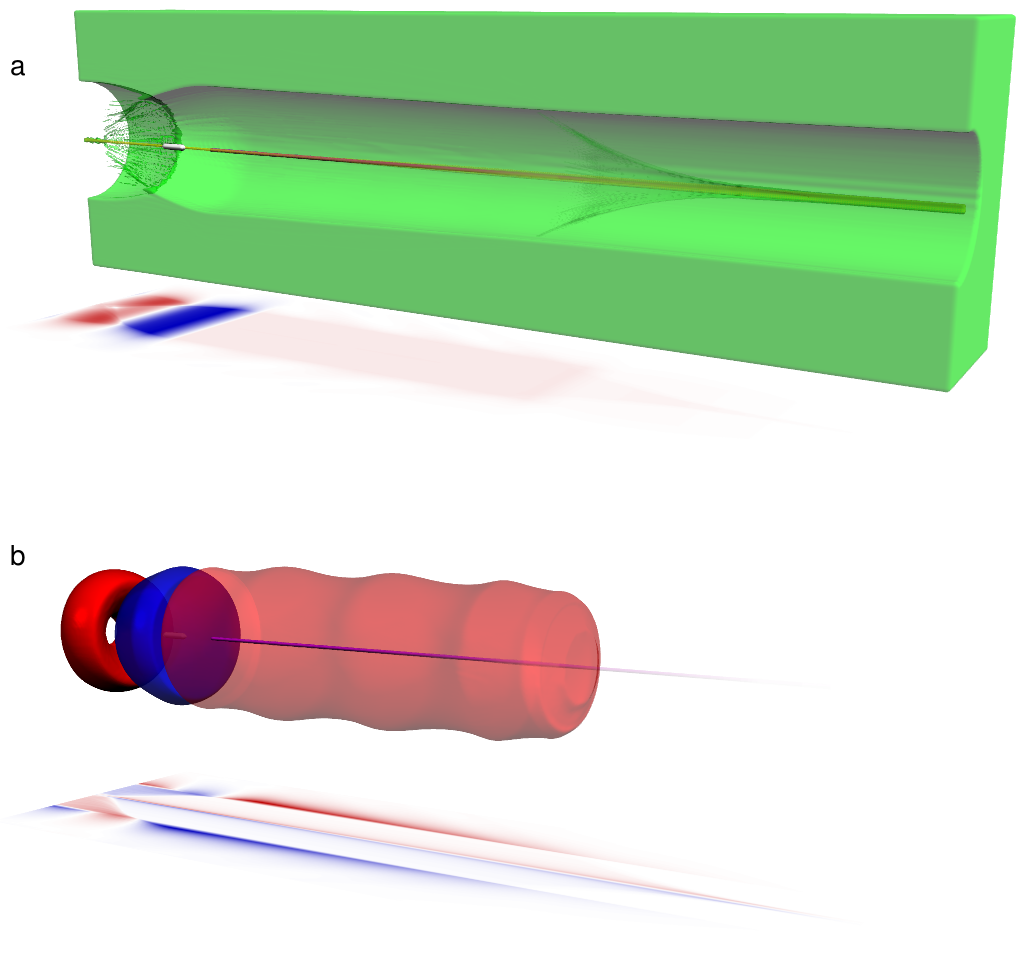
Here we show that stable acceleration in a hollow plasma channel can be achieved through the inclusion of a thin co-axial plasma filament. The accelerator configuration is shown in Fig. 1. We assume the plasma density in the filament to be the same as in the walls of the channel. The filament radius must be small, so that . Here is the characteristic plasma wave number, with is the corresponding electron plasma frequency. If we use an electron drive bunch with a current , where is the natural current unit, the transverse self-field of the driver will scatter the plasma electrons from the filament. The remaining ion column will guide both the electron driver and a negatively charged witness. Simultaneously, the ion column will slowly pinch due to the high charge of the drive beam. The characteristic pinch time is , where is the ion mass and is the ion charge. As the ion pinch begins at the head of the driver, the ion density, and so the effective betatron frequency, increases along the length of the beam. The large effective chirp guarantees the bunch stability through the BNS mechanism Balakin et al. (1983); Stupakov (1997), even for a monoenergetic driver. This chirp is independent of the beam energy, allowing much larger chirp rates than can be achieved by tailoring the driver energy spread. This makes the configuration ideal for exploiting the large acceleration gradients possible in a plasma accelerator.
To demonstrate stable acceleration in a co-axial channel, we use the fully three-dimensional quasi-static particle-in-cell code qv3d, developed on the platform of the VLPL code Pukhov (2016). This makes possible simulations that would be infeasible using conventional simulation methods 111Simulations were carried out in the light frame, , with a resolution of , , and a simulation box size of . The plasma response was modelled with a timestep , with the witness and drive beams subcycled with a timestep in order to correctly resolve the betatron frequency. 4 particles per cell were used for the bulk plasma, 64 for the drive beam and plasma filament, and 4096 for the witness bunch.. We choose helium as the background gas with an atomic density . The hollow plasma channel has a radius , and the on-axis plasma filament has a radius . In dimensional units, these are and . The filament and channel walls are taken to be singly ionized. We do not discuss here how such a plasma configuration may best be achieved. The standard method to create a hollow channel is by laser ionization Lindstrøm et al. (2018). The co-axial filament could, for example, be ionized by a higher-order laser mode or even by the self-field of the drive bunch Tarkeshian et al. (2018).
Both the driver and witness have an initial particle energy of , a negligibly small energy spread, and an emittance of . The driver consists of two bunches. The main driver has a ramped density profile, with a current increasing from zero to over , and a Gaussian transverse profile with . This bunch duration is approximately equal to the characteristic pinch time for the ion column.
Such ramped density profiles minimize the decelerating field acting on the driver Bane et al. (1985), allowing a larger transformer ratio. However, the high-current driver used here modifies the equilibrium radius of the channel and induces a return current in the bulk plasma. This results in a larger effective accelerator loss factor Schroeder et al. (1999) for higher beam currents, i.e. a stronger coupling between the drive beam and the channel. The optimal gradient for the main drive bunch is therefore sublinear. We here make use of a logarithmic ramp profile , with , which corresponds to a first-order correction to the plasma response.
An additional nonlinear wake term arises due to the scattering of electrons from the on-axis filament. This increases the decelerating field near the leading edge of the driver, reducing the transformer ratio obtained from commonly-used driver profiles, e.g. the double-triangular bunch Jiang et al. (2012). We avoid this limitation through the use of a second drive bunch which precedes the main driver, scattering the filament electrons before the peak decelerating field is reached. The leading bunch has a Gaussian rise, , with a sharp cut to zero at its peak of . The transverse profile is the same as the main driver. The two drive bunches partially overlap, with the start of the main driver before the peak of the preceding bunch.
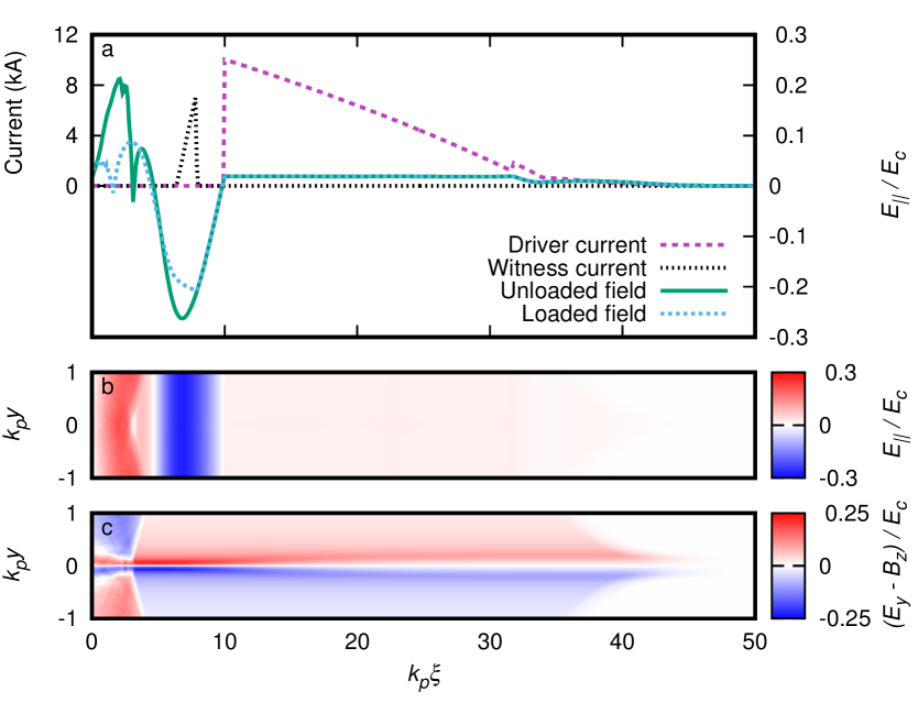
The combined current profile of the two drive bunches, and the resulting wakefield, is shown in Fig. 2a. The maximum decelerating field is , where the critical field for the chosen plasma density. The field structure has an unloaded transformer ratio . This value is % of the theoretical maximum for a main drive bunch of this length Baturin and Zholents (2017) in a hollow channel of this radius Schroeder et al. (1999). We note that the decelerating field after the peak is flat to within %. Further optimization would require a higher-order treatment for the plasma response.
The leading edge of the witness is located behind the rear edge of driver. Its transverse profile is Gaussian with , and a peak current of at its leading edge, decreasing linearly over its length. This density profile is chosen to correctly load the wakefield. The average accelerating field experienced by the witness corresponds to a loaded transformer ratio .
The longitudinal () and transverse () fields near the channel axis are shown for the unloaded accelerator in Figs. 2b and c. The accelerating and focusing fields are The chirp in the transverse focusing field arising from the pinch of the ion column is immediately apparent.
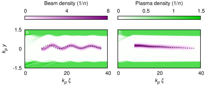
Without the co-axial plasma filament the driver rapidly becomes transversely unstable. The BBU growth observed in the qv3d code is in good agreement with analytical models, as seen in Fig. 3, which compares simulations with the numerical solution of Eq. (13) from reference Schroeder et al. (1999). The results diverge as the plasma response becomes nonlinear due to the limitations of the analytic model. Without a plasma filament, simulations for the same parameters as used in Fig. 1 show the loss of the witness beam due to BBU over distances as short as , limiting the energy gain to .
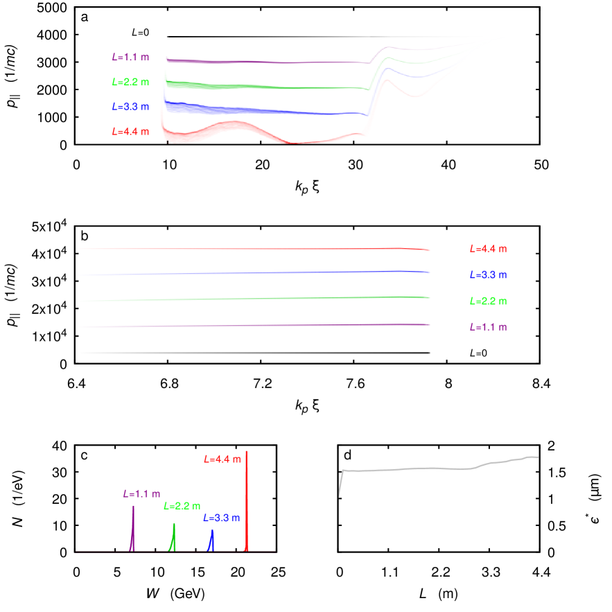
The presence of the co-axial plasma filament, however, stabilizes the system so that BBU is avoided completely. We follow the acceleration over a total distance of . The phase-space evolution of the driver is shown in Fig. 4a. We observe that at the end of the acceleration length, the driving bunches have lost % of their total energy.
The phase-space evolution of the witness bunch is shown in Fig. 4b. The witness initially develops a negative energy chirp, in agreement with the field at shown in Fig.2. However, as the witness is accelerated, it dephases with the drive beam, and so experiences a non-constant accelerating field over the acceleration length. As we carefully tuned the initial parameters, the gradient of the accelerating field acting on the witness is reversed after an acceleration length of , reducing the chirp.
Figure 4c shows the energy spectra of the witness bunch. The energy spread initially increases due to the chirp, and subsequently decreases, reaching a near-monoenergetic peak at for an acceleration distance of . For the witness charge of 410 pC, this corresponds to a total energy of – an energy gain of . Given the initial driver energy of for the 10 nC beam, this represents a 40% efficiency. Comparing only the energy lost by the driver gives a transfer efficiency of 46%. The measured energy spread % is limited by the simulation resolution.
The normalized emittance of the witness grows rapidly at the start of the simulation from to , and shows only slight growth over the acceleration length, reaching after , as seen in Fig 4d. The rapid growth of the initial emittance is likely numerical in nature. The resolution-limited emittance at the start of the simulation is estimated at 222Numerical Cherenkov radiation can lead to nonphysical emittance growth in standard Yee-like PIC codes Lehe et al. (2013). However, the quasistatic nature of the qv3d code makes it naturally free from this numerical artefact. The minimum emittance that can be accurately modelled is therefore limited only by the simulation resolution. We consider a particle beam focused down to a radius , with particles oscillating at the betatron frequency uniformly distributed over all phases. The normalized transverse emittance is then . Choosing a beam diameter of one cell, , and noting from simulations that the ion column density at the position of the witness is gives the resolution limit for the normalized transverse emittance as . .
The leading edge of the driver expands freely due to its initial emittance, but this leads only to a small perturbation of the wakefield. For longer propagation distances, this could be compensated with an external focusing field. Simulations show that the slow pinch of the ion column is vital for beam stabilization - the same configuration with a heavier ion species again results in BBU. Helium also has the desirable property that no secondary ionization occurs for these parameters. Dark current injection is avoided, as electrons streaming back from the bulk plasma behind the driver arrive only after the first potential bucket.
The use of plasma as the acceleration medium makes this acceleration scheme extremely flexible. All lengths scale directly with the plasma wavelength, and so, if desired, a wider channel in a lower-density plasma can be used to give the same acceleration over a longer propagation distance, which may be easier to achieve experimentally. The plasma density used here here represents the upper limit for this configuration. At higher densities, the self-field of the driver becomes sufficient to ionize the bulk gas in the channel. However, it is also possible to make use of a lower-current driver over a longer propagation distance, which reduces the required beam charge. In this case, the optimal shape of the driver will be slightly altered due to the nonlinearity of the plasma response.
Due to the use of an ion-column to focus the beam, this mechanism is only appropriate for an electron driver. However, we note that this configuration could be used to accelerate a positron witness bunch with a donut profile. Electrons from the bulk plasma stream back to compensate the ion filament behind the driver, leading to a inversion of the transverse field a short distance from the axis, as can be seen from Fig. 1c. This results in a stable point at which positrons may be accelerated. Comparing with Fig. 1b shows this point coincides with a large positive wakefield. However, the optimization is somewhat more complex than for an electron witness, and so will be discussed in detail in a separate work.
To conclude, we have shown that the use of a co-axial plasma filament within a hollow plasma channel prevents the development of the beam-breakup instability. In the short term, this configuration may serve as a pre-acceleration scheme for a conventional accelerator, increasing the dipole field strength at injection. Ultimately, though, the ability to stably and efficiently accelerate a witness bunch in a single stage finally offers a path towards a new generation of novel high-energy plasma-based accelerators. The combination of high transformer ratio and monoenergetic acceleration potentially makes this technology a serious contender for applications-driven research.
This work has been supported by the Deutsche Forschungsgemeinschaft and by BMBF.
References
- Esarey et al. (2009) E. Esarey, C. B. Schroeder, and W. P. Leemans, Rev. Mod. Phys. 81, 1229 (2009).
- Joshi and Caldwell (2013) C. Joshi and A. Caldwell, in Accelerators and Colliders, edited by S. Myers and H. Schopper (Springer Berlin Heidelberg, Berlin, Heidelberg, 2013) Chap. 12.1, pp. 592–605.
- Pukhov and Meyer-ter Vehn (2002) A. Pukhov and J. Meyer-ter Vehn, Appl. Phys. B 74, 355 (2002).
- Blumenfeld et al. (2007) I. Blumenfeld, C. E. Clayton, F.-J. Decker, M. J. Hogan, C. Huang, R. Ischebeck, R. Iverson, C. Joshi, T. Katsouleas, N. Kirby, W. Lu, K. A. Marsh, W. B. Mori, P. Muggli, E. Oz, R. H. Siemann, D. Walz, and M. Zhou, Nature 445, 741 (2007).
- Steinke et al. (2016) S. Steinke, J. van Tilborg, C. Benedetti, C. G. R. Geddes, C. B. Schroeder, J. Daniels, K. K. Swanson, A. J. Gonsalves, K. Nakamura, N. H. Matlis, B. H. Shaw, E. Esarey, and W. P. Leemans, Nature 530, 190 EP (2016).
- Rosenzweig et al. (2010) J. B. Rosenzweig, G. Andonian, M. Ferrario, P. Muggli, O. Williams, V. Yakimenko, and K. Xuan, AIP Conference Proceedings 1299, 500 (2010).
- Lu et al. (2006) W. Lu, C. Huang, M. Zhou, W. B. Mori, and T. Katsouleas, Phys. Rev. Lett. 96, 165002 (2006).
- Golovanov et al. (2016) A. A. Golovanov, I. Y. Kostyukov, J. Thomas, and A. Pukhov, Phys. Plasmas 23, 093114 (2016).
- Pukhov et al. (2011) A. Pukhov, N. Kumar, T. Tückmantel, A. Upadhyay, K. Lotov, P. Muggli, V. Khudik, C. Siemon, and G. Shvets, Phys. Rev. Lett. 107, 145003 (2011).
- Muggli et al. (2018) The AWAKE collaboration, Plasma Phys. Controlled Fusion 60, 014046 (2018).
- Andreev et al. (1997) N. E. Andreev, L. M. Gorbunov, V. I. Kirsanov, K. Nakajima, and A. Ogata, Phys. Plasmas 4, 1145 (1997).
- Kimura et al. (2011) W. D. Kimura, H. M. Milchberg, P. Muggli, X. Li, and W. B. Mori, Phys. Rev. ST Accel. Beams 14, 041301 (2011).
- Yi et al. (2014) L. Yi, B. Shen, L. Ji, K. Lotov, A. Sosedkin, XiaomeiZhang, W. Wang, J. Xu, Y. Shi, L. Zhang, and Z. Xu, Sci. Rep. 4, 4171 (2014).
- Behnke et al. (2013) T. Behnke, J. E. Brau, B. Foster, J. Fuster, M. Harrison, J. McEwan Paterson, M. Peskin, M. Stanitzki, N. Walker, and H. Yamamoto, The International Linear Collider Technical Design Report - Volume 1: Executive Summary, Tech. Rep. (The International Linear Collider, 2013).
- Tschentscher et al. (2006) T. Tschentscher, M. Altarelli, R. Brinkmann, T. Delissen, A. Schwarz, and K. Witte, Synchrotron Radiation News 19, 13 (2006).
- Schroeder et al. (1999) C. B. Schroeder, D. H. Whittum, and J. S. Wurtele, Phys. Rev. Lett. 82, 1177 (1999).
- Lindstrøm et al. (2018) C. A. Lindstrøm, E. Adli, J. M. Allen, W. An, C. Beekman, C. I. Clarke, C. E. Clayton, S. Corde, A. Doche, J. Frederico, S. J. Gessner, S. Z. Green, M. J. Hogan, C. Joshi, M. Litos, W. Lu, K. A. Marsh, W. B. Mori, B. D. O’Shea, N. Vafaei-Najafabadi, and V. Yakimenko, Phys. Rev. Lett. 120, 124802 (2018).
- Whittum et al. (1991) D. H. Whittum, W. M. Sharp, S. S. Yu, M. Lampe, and G. Joyce, Phys. Rev. Lett. 67, 991 (1991).
- Li et al. (2014) C. Li, W. Gai, C. Jing, J. G. Power, C. X. Tang, and A. Zholents, Phys. Rev. ST Accel. Beams 17, 091302 (2014).
- Panofsky and Bander (1968) W. K. H. Panofsky and M. Bander, Review of Scientific Instruments 39, 206 (1968), https://doi.org/10.1063/1.1683315 .
- Balakin et al. (1983) V. E. Balakin, A. V. Novokhatsky, and V. P. Smirnov, in Proceedings, 12th International Conference on High-Energy Accelerators, HEACC 1983: Fermilab, Batavia, August 11-16, 1983, Vol. C830811 (1983) pp. 119–120.
- Stupakov (1997) G. V. Stupakov, SLAC-AP-108 (1997).
- Zholents et al. (2016) A. Zholents, W. Gai, S. Doran, R. Lindberg, J. Power, N. Strelnikov, Y. Sun, E. Trakhtenberg, I. Vasserman, C. Jing, A. Kanareykin, Y. Li, Q. Gao, D. Shchegolkov, and E. Simakov, Nuclear Instruments and Methods in Physics Research Section A: Accelerators, Spectrometers, Detectors and Associated Equipment 829, 190 (2016), (2nd European Advanced Accelerator Concepts Workshop - EAAC 2015).
- Baturin and Zholents (2018) S. S. Baturin and A. Zholents, Phys. Rev. Accel. Beams 21, 031301 (2018).
- Huang et al. (2007) C. Huang, W. Lu, M. Zhou, C. E. Clayton, C. Joshi, W. B. Mori, P. Muggli, S. Deng, E. Oz, T. Katsouleas, M. J. Hogan, I. Blumenfeld, F. J. Decker, R. Ischebeck, R. H. Iverson, N. A. Kirby, and D. Walz, Phys. Rev. Lett. 99, 255001 (2007).
- Mehrling et al. (2017) T. J. Mehrling, R. A. Fonseca, A. Martinez de la Ossa, and J. Vieira, Phys. Rev. Lett. 118, 174801 (2017).
- Martinez de la Ossa et al. (2018) A. Martinez de la Ossa, T. J. Mehrling, and J. Osterhoff, Phys. Rev. Lett. 121, 064803 (2018).
- Pukhov (2016) A. Pukhov, CERN Yellow Reports 1, 181 (2016).
- Note (1) Simulations were carried out in the light frame, , with a resolution of , , and a simulation box size of . The plasma response was modelled with a timestep , with the witness and drive beams subcycled with a timestep in order to correctly resolve the betatron frequency. 4 particles per cell were used for the bulk plasma, 64 for the drive beam and plasma filament, and 4096 for the witness bunch.
- Tarkeshian et al. (2018) R. Tarkeshian, J. L. Vay, R. Lehe, C. B. Schroeder, E. H. Esarey, T. Feurer, and W. P. Leemans, Phys. Rev. X 8, 021039 (2018).
- Bane et al. (1985) K. L. F. Bane, P. Chen, and P. B. Wilson, IEEE Transactions on Nuclear Science 32, 3524 (1985), also published in SLAC-PUB 3662 (1985) .
- Jiang et al. (2012) B. Jiang, C. Jing, P. Schoessow, J. Power, and W. Gai, Phys. Rev. ST Accel. Beams 15, 011301 (2012).
- Baturin and Zholents (2017) S. S. Baturin and A. Zholents, Phys. Rev. Accel. Beams 20, 061302 (2017).
- Note (2) Numerical Cherenkov radiation can lead to nonphysical emittance growth in standard Yee-like PIC codes Lehe et al. (2013). However, the quasistatic nature of the qv3d code makes it naturally free from this numerical artefact. The minimum emittance that can be accurately modelled is therefore limited only by the simulation resolution. We consider a particle beam focused down to a radius , with particles oscillating at the betatron frequency uniformly distributed over all phases. The normalized transverse emittance is then . Choosing a beam diameter of one cell, , and noting from simulations that the ion column density at the position of the witness is gives the resolution limit for the normalized transverse emittance as .
- Lehe et al. (2013) R. Lehe, A. Lifschitz, C. Thaury, V. Malka, and X. Davoine, Phys. Rev. ST Accel. Beams 16, 021301 (2013).